Data Sheet DB EN ILB BT ADIO 2/2/16/16
Data Sheet DB EN ILB BT ADIO 2/2/16/16
Data Sheet DB EN ILB BT ADIO 2/2/16/16
- TAGS
- adio
- www.megachip.ru

You also want an ePaper? Increase the reach of your titles
YUMPU automatically turns print PDFs into web optimized ePapers that Google loves.
<strong>ILB</strong> <strong>BT</strong> <strong>ADIO</strong> 2/2/<strong>16</strong>/<strong>16</strong><br />
Bluetooth I/O Module<br />
With <strong>16</strong> Digital Inputs and <strong>16</strong> Digital Outputs<br />
and 2 Analog Inputs and 2 Analog Outputs<br />
AUTOMATIONWORX<br />
<strong>Data</strong> <strong>Sheet</strong><br />
7476_en_02<br />
Description<br />
The <strong>ILB</strong> <strong>BT</strong> <strong>ADIO</strong> 2/2/<strong>16</strong>/<strong>16</strong> module is used to acquire and<br />
output digital and analog signals. It uses wireless<br />
transmission to send <strong>16</strong> digital and two analog input and<br />
output signals to the relevant Bluetooth base station.<br />
Features of the Radio Interface<br />
– Bluetooth 1.2, HID profile<br />
– Frequency range from 2.4000 GHz to 2.4835 GHz,<br />
ISM band<br />
– The maximum emitted transmission power can be set<br />
between 0 dBm/1 mW and <strong>16</strong> dBm/39.8 mW,<br />
automatically controlled<br />
– Diagnostic and status indicators<br />
Features of Digital Inputs<br />
– Connections for <strong>16</strong> digital sensors<br />
– Connection of sensors in single-wire technology<br />
– Status indicators<br />
Features of Digital Outputs<br />
– Connections for <strong>16</strong> digital actuators<br />
– Connection of actuators in single-wire technology<br />
© PHO<strong>EN</strong>IX CONTACT - 10/2007<br />
Make sure you always use the latest documentation.<br />
It can be downloaded at www.download.phoenixcontact.com.<br />
A conversion table is available on the Internet at<br />
www.download.phoenixcontact.com/general/7000_en_00.pdf.<br />
– Nominal current per output: 0.5 A<br />
– Total current of all outputs: 8 A<br />
– Short-circuit and overload protected outputs<br />
– Status indicators<br />
Features of Analog Inputs<br />
– Two analog single-ended signal inputs for the<br />
connection of either voltage or current signals<br />
– Connection of sensors in 2 and 3-wire technology<br />
– Current measuring range of 0 mA to 20 mA<br />
– Voltage measuring range of 0 V to 10 V<br />
Features of Analog Outputs<br />
– Two analog single-ended signal outputs for the<br />
connection of either voltage or current signals<br />
– Connection of actuators in 2 and 3-wire technology<br />
– Current measuring range of 0 mA to 20 mA<br />
– Voltage measuring range of 0 V to 10 V<br />
Please refer to the application note for instructions on how to assemble/remove the module.
Usage Notes<br />
This device contains:<br />
FCC ID: PVH071902<br />
IC: 5325A-0719X<br />
This device complies with Part 15 of the FCC Rules.<br />
Operation is subject to the following two conditions:<br />
(1) this device may not cause harmful interference, and (2)<br />
this device must accept any interference received,<br />
including interference that may cause undesired<br />
operations.<br />
The <strong>ILB</strong> <strong>BT</strong> <strong>ADIO</strong> 2/2/<strong>16</strong>/<strong>16</strong> module must only<br />
be operated in the following countries:<br />
Austria, Belgium, Bulgaria, Canada, Cyprus,<br />
Czech Republic, Denmark, Estonia, Finland,<br />
France, Germany, Great Britain, Greece,<br />
Hungary, Iceland, Ireland, Italy, Latvia,<br />
Lithuania, Luxembourg, Malta, the<br />
Netherlands, Norway (not including<br />
Spitzbergen), Poland, Portugal, Romania,<br />
Slovakia, Slovenia, Spain, Sweden,<br />
Switzerland, USA*)<br />
*) In outdoor installations, the device may only<br />
be operated with an emitted power of 10 dBm<br />
maximum from the antenna<br />
Please note the maximum permissible emitted<br />
transmission power for the country of use.<br />
The use of products described in this data<br />
sheet is oriented exclusively to qualified<br />
electricians or persons instructed by them, who<br />
are familiar with applicable national standards<br />
and other regulations regarding electrical<br />
engineering and, in particular, the relevant<br />
safety concepts.<br />
Phoenix Contact accepts no liability for<br />
erroneous handling or damage to products<br />
from Phoenix Contact or third-party products<br />
resulting from disregard of information<br />
contained in this data sheet.<br />
<strong>ILB</strong> <strong>BT</strong> <strong>ADIO</strong> 2/2/<strong>16</strong>/<strong>16</strong><br />
The wireless system complies with the basic<br />
requirements and other relevant regulations<br />
specified in directive 1999/5/EU.<br />
7476_en_02 PHO<strong>EN</strong>IX CONTACT 2
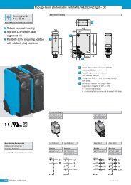
Transmission Power<br />
Depending on the maximum possible transmission power,<br />
the operation of this device must be notified or approved in<br />
some countries. Occasionally, usage restrictions may apply<br />
for the transmission power for indoor or outdoor use.<br />
Before device startup, the maximum permissible<br />
transmission power must be set (default upon delivery:<br />
<strong>16</strong> dBm). The antenna gain of the antenna used should be<br />
taken into account. For the antenna provided (gain 0 dBi),<br />
the transmission power values printed on the device apply.<br />
The maximum transmission power is set using DIP<br />
switches on the rear of the device.<br />
To apply the transmission power setting, restart the device.<br />
DIP MODE<br />
<strong>16</strong><br />
dBm<br />
12<br />
dBm<br />
8<br />
dBm<br />
4<br />
dBm<br />
0<br />
dBm<br />
Figure 1 DIP switches for setting the transmission<br />
power<br />
<strong>ILB</strong> <strong>BT</strong> <strong>ADIO</strong> 2/2/<strong>16</strong>/<strong>16</strong><br />
7476_en_02 PHO<strong>EN</strong>IX CONTACT 3
Ordering <strong>Data</strong><br />
<strong>ILB</strong> <strong>BT</strong> <strong>ADIO</strong> 2/2/<strong>16</strong>/<strong>16</strong><br />
Module<br />
Description Type Order No. Pcs./Pck.<br />
Bluetooth I/O module with <strong>16</strong> digital inputs and <strong>16</strong> digital outputs and two<br />
analog inputs and two analog outputs<br />
<strong>ILB</strong> <strong>BT</strong> <strong>ADIO</strong> 2/2/<strong>16</strong>/<strong>16</strong> 2884282 1 set<br />
Fieldline Modular Bluetooth base station FLM <strong>BT</strong> BS3 M12 2736770 1<br />
Factory Line Bluetooth base station FL <strong>BT</strong> MOD IO AP 2884758 1<br />
Accessories<br />
Connectors as Replacement Item Type Order No. Pcs./Pck.<br />
Shield connector IB IL SCN-6 SHIELD-TWIN 2740245 5<br />
Connector for the supply (with color print) IB IL SCN-PWR IN-CP 2727637 10<br />
Connector for input and output terminals<br />
Antennas<br />
IB IL SCN-8 2726337 10<br />
Panel antenna RAD-ISM-2400-ANT-PAN-8-0 2867610 1<br />
Pigtail antenna cable for panel antenna RAD-PIG-EF-3<strong>16</strong>-SMA-SMA 2885618 1<br />
Omnidirectional antenna with protection against vandalism RAD-ISM-2400-ANT-VAN-3-0-SMA 2885867 1<br />
Additional Accessories<br />
Only use approved accessories.<br />
Recommended end clamp; placed to the right of the module<br />
to secure it on the DIN rail<br />
Accessories for extending the antenna cable are available on request.<br />
CLIPFIX 35-5 3022276 50<br />
7476_en_02 PHO<strong>EN</strong>IX CONTACT 4
Technical <strong>Data</strong><br />
General <strong>Data</strong><br />
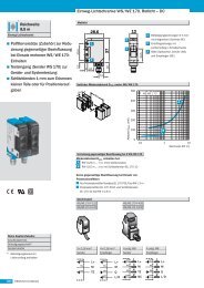
Housing dimensions with connectors (width x height x depth) 117 mm x 73 mm x 121 mm<br />
Weight (without antenna) 305 g (with connectors, ID plug, and antenna)<br />
Connection method for sensors and actuators Single-wire technology<br />
Housing Dimensions<br />
121<br />
Figure 2 Housing dimensions of the module (mm)<br />
Ambient Conditions<br />
117 57<br />
7476A002<br />
Regulations Developed according to VDE 0<strong>16</strong>0, UL 508<br />
Ambient temperature (operation) -25°C to +60°C<br />
Ambient temperature (storage/transport) -25°C to +85°C<br />
Humidity (operation) 75% on average, 85% occasionally, no condensation<br />
In the range from -25°C to +60°C appropriate measures against increased humidity (> 85%) must be taken.<br />
Humidity (storage/transport) 95%<br />
<strong>ILB</strong> <strong>BT</strong> <strong>ADIO</strong> 2/2/<strong>16</strong>/<strong>16</strong><br />
For a short period, slight condensation may appear on the outside of the housing if, for example, the module is brought into a closed room<br />
from a vehicle.<br />
Air pressure (operation) 80 kPa to 108 kPa (up to 2000 m above sea level)<br />
Air pressure (storage/transport) 66 kPa to 108 kPa (up to 3500 m above sea level)<br />
Degree of protection according to DIN 40050, IEC 60529 IP20<br />
Protection class according to <strong>EN</strong> 61131-2, IEC 61131-2 3<br />
Air and creepage distances According to IEC 60664/IEC 60664A DIN VDE 0110: 1989-01 and<br />
DIN VDE 0<strong>16</strong>0: 1988-05<br />
7476_en_02 PHO<strong>EN</strong>IX CONTACT 5<br />
73
Ambient Conditions (Continued)<br />
Housing material Plastic, PVC-free, P<strong>BT</strong>, self-extinguishing (V0)<br />
Pollution degree according to <strong>EN</strong> 60664, <strong>EN</strong> 61131-2 2; condensation not permitted during operation<br />
Surge voltage class II<br />
Electrical Isolation/Isolation of the Voltage Areas<br />
Common Potentials<br />
24 V communications power, 24 V actuator supply, and GND have the same potential. FE is a separate potential area.<br />
- Test Distance - Test Voltage<br />
24 V supply (I/O)/functional earth ground 500 V AC, 50 Hz, 1 min.<br />
24 V supply (I/O)/analog channels 500 V AC, 50 Hz, 1 min.<br />
Analog channels/FE 500 V AC, 50 Hz, 1 min.<br />
Mechanical Requirements<br />
Vibration test sinusoidal vibrations according to IEC 60068-2-29;<br />
<strong>EN</strong> 60068-2-29<br />
5g load, 2.5 hours in each space direction<br />
Shock test according to IEC 60068-2-27; <strong>EN</strong> 60068-2-27 25g load for 11 ms, half sinusoidal wave,<br />
3 shocks in each space direction and orientation<br />
Broadband noise according to IEC 60068-2-64; <strong>EN</strong> 60068-2-64 0.78g load, 2.5 hours in each space direction<br />
Conformance With EMC Directive 89/336/EEC<br />
Noise Immunity Test According to <strong>EN</strong> 61000-6-2<br />
Electrostatic discharge (ESD) <strong>EN</strong> 61000-4-2<br />
IEC 61000-4-2<br />
Electromagnetic fields <strong>EN</strong> 61000-4-3<br />
IEC 61000-4-3<br />
Fast transients (burst) <strong>EN</strong> 61000-4-4/<br />
IEC 61000-4-4<br />
Surge voltage <strong>EN</strong> 61000-4-5<br />
IEC 61000-4-5<br />
Conducted interference <strong>EN</strong> 61000-4-6<br />
IEC 61000-4-6<br />
Noise Emission Test According to <strong>EN</strong> 61000-6-4<br />
Criterion B<br />
6 kV contact discharge<br />
8 kV air discharge<br />
Criterion A<br />
Field strength: 10 V/m<br />
Criterion B<br />
Remote bus: 2 kV<br />
Power supply: 2 kV<br />
I/O cables: 2 kV<br />
Criterion A<br />
All interfaces: 1 kV<br />
Criterion B<br />
DC supply lines: ±0.5 kV/±0.5 kV<br />
(symmetrical/asymmetrical)<br />
Signal cables: ±0.5 kV/±0.5 kV<br />
(symmetrical/asymmetrical)<br />
Criterion A<br />
Test voltage 10 V<br />
Noise emission of housing <strong>EN</strong> 55011 Class A (industrial applications)<br />
Test for Radio Approval<br />
EMC ETSI <strong>EN</strong> 301 489-17<br />
Radio ETSI <strong>EN</strong> 300 328<br />
Safety <strong>EN</strong> 60950-1<br />
Health <strong>EN</strong> 50371<br />
Radio Interface<br />
Radio interface Bluetooth 1.2<br />
Frequency range 2.4000 GHz to 2.4835 GHz<br />
Channel distance 1 MHz<br />
Number of channels 79<br />
<strong>ILB</strong> <strong>BT</strong> <strong>ADIO</strong> 2/2/<strong>16</strong>/<strong>16</strong><br />
7476_en_02 PHO<strong>EN</strong>IX CONTACT 6
Radio Interface (Continued)<br />
Modulation GFSK (Gaussian Frequency Shift Keying)<br />
<strong>ILB</strong> <strong>BT</strong> <strong>ADIO</strong> 2/2/<strong>16</strong>/<strong>16</strong><br />
Maximum transmission power at the antenna connection Can be set between 0 dBm/1 mW and <strong>16</strong> dBm/39.8 mW in 4 dB increments<br />
Antenna connection SMA female connector<br />
24 V Module Supply<br />
Communications Power<br />
Nominal value 24 V DC<br />
Tolerance -15%/+20% according to <strong>EN</strong> 61131-2<br />
Ripple ±5% according to <strong>EN</strong> 61131-2<br />
Permissible range 19.2 V ... 30.0 V<br />
Current consumption at UL 75 mA<br />
Protection against polarity reversal Yes<br />
Surge protection Yes<br />
Connection Via power connectors<br />
Actuator Supply<br />
Nominal value 24 V DC<br />
Tolerance -15%/+20% according to <strong>EN</strong> 61131-2<br />
Ripple ±5% according to <strong>EN</strong> 61131-2<br />
Permissible range 19.2 V ... 30.0 V<br />
Current consumption at UL 8 A, maximum<br />
Number of isolated groups 1<br />
Overload protection Yes<br />
Protection against polarity reversal No<br />
Connection Via power connectors<br />
Digital Outputs<br />
Number <strong>16</strong><br />
Number of voltage groups 1<br />
Connection method for actuators Single-wire technology<br />
Nominal output voltage UOUT 24 V DC<br />
Differential voltage for Inom ≤ 1 V<br />
Nominal current Inom per channel 0.5 A<br />
Total current 8 A<br />
Protection<br />
Nominal load<br />
Short circuit; overload<br />
Ohmic 48 Ω/12 W<br />
Lamp 12 W<br />
Inductive 12 VA (1.2 H, 50 Ω)<br />
Switching frequency with nominal inductive load 0.5 Hz (1.2 H, 50 Ω)<br />
Overload response Auto restart<br />
Response with inductive overload Output may be damaged<br />
Reverse voltage protection against short pulses Yes<br />
Resistance to permanently applied reverse voltages Yes, maximum permissible current 2 A<br />
Response upon power down The output follows the supply voltage without delay.<br />
Limitation of the voltage induced on circuit interruption -41 V<br />
Single maximum energy in free running 1 J, maximum<br />
Protective circuit type Integrated free running circuit in the output chip<br />
Overcurrent shutdown 0.7 A, minimum<br />
Maximum output current when switched off 10 µA<br />
When not loaded, a voltage can be measured even at an output that is not set.<br />
7476_en_02 PHO<strong>EN</strong>IX CONTACT 7
Digital Inputs<br />
Number <strong>16</strong><br />
<strong>ILB</strong> <strong>BT</strong> <strong>ADIO</strong> 2/2/<strong>16</strong>/<strong>16</strong><br />
Connection method for sensors Single-wire technology<br />
Input design<br />
Definition of switching thresholds<br />
According to <strong>EN</strong> 61131-2 Type 1<br />
Maximum low-level voltage ULmax < 5 V<br />
Minimum high-level voltage UHmin > 15 V<br />
Common potentials Ground<br />
Nominal input voltage UIN 24 V DC<br />
Permissible range -30 V < UIN < +30 V DC<br />
Nominal input current for UIN 3.6 mA per channel, typical<br />
Current flow Linear in the range 1 V < UIN < 30 V<br />
Delay time ≤ 300 µs<br />
Permissible cable length to the sensor 100 m<br />
Use of AC sensors AC sensors in the voltage range < UIN are limited in application<br />
Typical Power Dissipation With 24 V Supply Voltage<br />
Formula to calculate the power dissipation of the electronics<br />
<strong>16</strong> <strong>16</strong><br />
2<br />
P = 0.552 W + �( 0.065 W + I x 0.28 �) + � 0.086 W + � 0.372 W + � 0.044 W<br />
TOT Ln<br />
n=0 m=0<br />
Where<br />
PTOT Total power dissipation of the module<br />
n Index of the number of set digital outputs (n = 0 to <strong>16</strong>)<br />
ILn Load current of output n<br />
m Index of the number of set digital inputs (m = 0 to <strong>16</strong>)<br />
I Index of the number of analog outputs used (I = 0 to 2)<br />
k Index of the number of analog inputs used (k = 0 to 2)<br />
Simultaneity, Derating<br />
No limitation of simultaneity, derating<br />
Output Derating<br />
Ambient Temperature (TA) Total Current (ITOT) -25°C ... +50°C 8 A<br />
+50°C ... +60°C 8 A - ((TA - 50°C) x 0.4 A/°C)<br />
7476_en_02 PHO<strong>EN</strong>IX CONTACT 8<br />
2<br />
l=0<br />
2<br />
k=0<br />
1 6 � 6<br />
)<br />
&<br />
"<br />
� #<br />
% % ! ) %<br />
#<br />
6 )<br />
$<br />
� +
Analog Outputs<br />
Number<br />
Signals/resolution<br />
2<br />
0 V ... 10 V voltage 2.44 mV<br />
0 mA ... 20 mA current<br />
Output load<br />
4.88 µA<br />
Voltage output 2 kΩ, minimum<br />
Current output 0 Ω ... 500 Ω<br />
Representation of Output Values<br />
The output value is represented in bits 14 to 0. An additional bit (bit 15) is available as a sign bit.<br />
Representation of output values<br />
MSB LSB<br />
15 14 13 12 11 10 9 8 7 6 5 4 3 2 1 0<br />
SB Analog value<br />
Significant Output Values<br />
Output range 0 mA to 20 mA and 0 V to 10 V<br />
Safety Equipment<br />
Output <strong>Data</strong> Word<br />
(Two's Complement)<br />
7476b006<br />
0mA to 20mA<br />
I Output<br />
<strong>ILB</strong> <strong>BT</strong> <strong>ADIO</strong> 2/2/<strong>16</strong>/<strong>16</strong><br />
0V to 10V<br />
U Output<br />
hex dec mA V<br />
≤FFFF ≤32767 +21.6746 +10.837<br />
≤7F00 32512 +21.6746 +10.837<br />
7530 30000 +20.0 +10.0<br />
0001 1 +0.66667 µA +333.33 µV<br />
0000 0 0 0<br />
Transient protection at voltage and current outputs<br />
Tolerance and Temperature Response of Analog Outputs<br />
The tolerance values refer to the measuring range final value.<br />
Tolerances at TA = +23°C<br />
Measuring Range Absolute (Typical) Absolute (Maximum) Relative (Typical) Relative (Maximum)<br />
0 V ... 10 V ±31 mV ±93 mV ±0.31% ±0.93%<br />
0 mA ... 20 mA ±112 µA ±194 µA ±0.56% ±0.97%<br />
Temperature and Drift Response (TA = -25°C to +60°C)<br />
Drift in reference to the measuring range final value.<br />
Measuring Range Typical Maximum<br />
0 V ... 10 V 306 ppm/K 750 ppm/K<br />
0 mA ... 20 mA 306 ppm/K 740 ppm/K<br />
7476_en_02 PHO<strong>EN</strong>IX CONTACT 9
Analog Inputs<br />
Voltage Inputs<br />
Input resistance > 150 kΩ<br />
Limit frequency (-3 dB) of the input filters 40 Hz<br />
Maximum permissible voltage between analog voltage inputs and analog<br />
reference potential<br />
±32 V<br />
Common mode rejection (CMR) 103 dB<br />
Permissible DC common mode voltage for CMR 40 V between voltage input and FE<br />
Current Inputs<br />
Input resistance 110 Ω (shunt)<br />
Limit frequency (-3 dB) of the input filters 40 Hz<br />
Maximum permissible voltage between analog current inputs and analog<br />
reference potential<br />
±32 V (the input voltage is limited internally)<br />
Common mode rejection (CMR) 103 dB<br />
Permissible DC common mode voltage for CMR 40 V between current input and FE<br />
Maximum permissible current Internally limited by protective circuit<br />
Safety Equipment<br />
Surge voltage Suppressor diodes in the analog inputs,<br />
current limitation via internal protective circuit<br />
<strong>ILB</strong> <strong>BT</strong> <strong>ADIO</strong> 2/2/<strong>16</strong>/<strong>16</strong><br />
Tolerance and Temperature Response of Analog Inputs<br />
The tolerance values refer to the measuring range final value.<br />
Tolerances at TA = +23°C<br />
Measuring Range Absolute (Typical) Absolute (Maximum) Relative (Typical) Relative (Maximum)<br />
0 V ... 10 V ±30 mV ±74 mV ±0.30% ±0.74%<br />
0 mA ... 20 mA ±80 µA ±<strong>16</strong>4 µA ±0.40% ±0.82%<br />
Temperature and Drift Response (TA = -25°C to +60°C)<br />
Drift in reference to the measuring range final value<br />
Measuring Range Typical Maximum<br />
0 V ... 10 V 40 ppm/K 170 ppm/K<br />
0 mA ... 20 mA 40 ppm/K 175 ppm/K<br />
Additional Tolerances Influenced by Electromagnetic Fields<br />
Type of Electromagnetic Interference Typical Deviation of the Measuring Range Final Value<br />
(Voltage and Current Channels)<br />
Relative<br />
Electromagnetic fields; field strength 10 V/m<br />
according to <strong>EN</strong> 61000-4-3/IEC 61000-4-3<br />
Conducted interference, Class 3 (10 V test voltage)<br />
according to <strong>EN</strong> 61000-4-6/IEC 61000-4-6<br />
Fast transients (burst); 4 kV supply, 2 kV input<br />
according to <strong>EN</strong> 61000-4-4/IEC 61000-4-4<br />
< ±0.5%<br />
< ±0.5%<br />
< ±0.5%<br />
Representation of Input Values<br />
The output value is represented in bits 14 to 0. An additional bit (bit 15) is available as a sign bit. This format supports<br />
extended diagnostics. Values > 8000hex indicate an error.<br />
Representation of input values<br />
MSB LSB<br />
15 14 13 12 11 10 9 8 7 6 5 4 3 2 1 0<br />
SB Analog value<br />
7476b006<br />
7476_en_02 PHO<strong>EN</strong>IX CONTACT 10
<strong>ILB</strong> <strong>BT</strong> <strong>ADIO</strong> 2/2/<strong>16</strong>/<strong>16</strong><br />
Significant Measured Values<br />
Output range 0 mA to 20 mA and 0 V to 10 V<br />
Input <strong>Data</strong> Word<br />
0mA to 20mA<br />
0V to 10V<br />
(Two's Complement)<br />
IInput UInput hex dec mA V<br />
8001 Overrange > +21.6746 > +10.837<br />
7F00 32512 +21.6746 +10.837<br />
7530 30000 +20.0 +10.0<br />
0001 1 +0.66667 µA +333.33 µV<br />
0000 0 0 0<br />
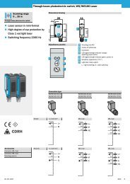
Local Diagnostic and Status Indicators<br />
UA<br />
UL<br />
PWR1<br />
BLUETOOTH<br />
UA<br />
UL<br />
PWR1<br />
DO DI<strong>16</strong><br />
AO2<br />
<strong>16</strong> AI2<br />
QUALITY<br />
LINK<br />
Figure 3 Diagnostic and status indicators of the module<br />
FS<br />
E DO<br />
<strong>16</strong><br />
1 2<br />
E<br />
9 10<br />
3 4 11 12<br />
5 6 13 14<br />
7 8 15 <strong>16</strong><br />
ID-<br />
PLUG<br />
AO2 LINK AI2<br />
QUALITY<br />
FS<br />
ID-<br />
PLUG<br />
DI<strong>16</strong><br />
1 2 9 10<br />
3 4 11 12<br />
5 6 13 14<br />
7 8 15 <strong>16</strong><br />
7476A003<br />
Designation<br />
PWR<br />
LED Color Meaning<br />
UA Green 24 V actuator supply<br />
UL<br />
OUT<br />
Green 24 V communications power<br />
E Red Short circuit or overload at one of the outputs<br />
1 to <strong>16</strong> Yellow Status indicators for the outputs<br />
IN<br />
FS<br />
1 to <strong>16</strong> Yellow Status indicators for the inputs<br />
FS Red Failsafe, analog and digital outputs set to 0<br />
7476_en_02 PHO<strong>EN</strong>IX CONTACT 11
Designation LED Color Meaning<br />
<strong>ILB</strong> <strong>BT</strong> <strong>ADIO</strong> 2/2/<strong>16</strong>/<strong>16</strong><br />
ID-PLUG<br />
ID Green/yellow/<br />
red<br />
ID plug status (normal operation)<br />
Green ON ID plug was read successfully<br />
Yellow ON Reading ID plug<br />
Red ON ID plug cannot be read<br />
OFF ID plug not present<br />
Green/yellow/<br />
red<br />
ID plug status (clear mode/Bluetooth network login)<br />
Attention/caution<br />
Please refer to the "Clearing and Reprogramming Function" section.<br />
Green flashing Ready for Bluetooth network login<br />
Yellow ON Ready to clear/program the ID plug<br />
LINK QUALITY<br />
LQ Quality of the Bluetooth connection (bit error rate; BER)<br />
4 green LEDs BER 0% - 0.05%<br />
3 green LEDs BER 0.05% - 0.1%<br />
2 green LEDs BER 0.1% - 1.7%<br />
1 green LED BER > 1.7%<br />
4 LEDs OFF No Bluetooth connection established<br />
If the error LED (E) of a group of <strong>16</strong> outputs lights up (e.g., connector 2 and connector 3), this indicates that a<br />
short circuit or overload is present at one or more of the outputs in this group.<br />
7476_en_02 PHO<strong>EN</strong>IX CONTACT 12
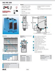
Connecting the Supply, Actuators, and Sensors<br />
1<br />
1.1<br />
1.2<br />
1.3<br />
1.4<br />
1<br />
2<br />
3<br />
4<br />
1<br />
2<br />
1<br />
2<br />
3<br />
4<br />
2.1<br />
2.2<br />
2.3<br />
BLUETOOTH<br />
2.4<br />
UA<br />
UL<br />
PWR1<br />
2-7<br />
DO DI<strong>16</strong><br />
AO2<br />
<strong>16</strong> AI2<br />
QUALITY<br />
LINK<br />
Figure 4 Terminal point assignment of the connectors<br />
Terminal Point Assignment of the Digital Output and Input Connectors<br />
Terminal Point Assignment of the Analog Output Connector<br />
Terminal Point Assignment of the Analog Input Connector<br />
1.1<br />
1.2<br />
1.3<br />
1.4<br />
FS<br />
1<br />
2<br />
3<br />
4<br />
1<br />
2<br />
1<br />
2<br />
3<br />
4<br />
7476A004<br />
2.1<br />
2.2<br />
2.3<br />
2.4<br />
<strong>ILB</strong> <strong>BT</strong> <strong>ADIO</strong> 2/2/<strong>16</strong>/<strong>16</strong><br />
The terminal points for GND and U L can have<br />
a total current of 8 A per terminal point. The<br />
maximum current carrying capacity of 8 A must<br />
not be exceeded.<br />
The supply points have the same ground<br />
potential. All ground supplies on a module are<br />
electrically connected with one another.<br />
The communications power is also electrically<br />
connected via all contacts. In this way, it can<br />
supply all potentials with just one supply<br />
without the need for additional terminals, see<br />
"Connection example for the supply" on<br />
page 15.<br />
Terminal Point Assignment of the Power Connector<br />
Terminal Point Assignment<br />
Connector 1 (PWR)<br />
1.1, 2.1 24 V actuator supply U A<br />
1.2, 2.2 24 V communications power U L<br />
1.3, 2.3 GND<br />
1.4, 2.4 FE<br />
Connector 2 (OUT1) Connector 3 (OUT2) Connector 4 (IN1) Connector 5 (IN2)<br />
1.1 Q1 2.1 Q2 1.1 Q9 2.1 Q10 1.1 I1 2.1 I2 1.1 I9 2.1 I10<br />
1.2 Q3 2.2 Q4 1.2 Q11 2.2 Q12 1.2 I3 2.2 I4 1.2 I11 2.2 I12<br />
1.3 Q5 2.3 Q6 1.3 Q13 2.3 Q14 1.3 I5 2.3 I6 1.3 I13 2.3 I14<br />
1.4 Q7 2.4 Q8 1.4 Q15 2.4 Q<strong>16</strong> 1.4 I7 2.4 I8 1.4 I15 2.4 I<strong>16</strong><br />
Connector 6 (Analog OUT)<br />
1.1 +U1, voltage output channel 1 2.1 +U2, voltage output channel 2<br />
1.2 +I1, current output channel 1 2.2 +I2, current output channel 2<br />
1.3 AGND, analog ground 2.3 AGND, analog ground<br />
1.4 Shield connection 2.4 Shield connection<br />
Connector 7 (Analog IN)<br />
1.1 +U1, voltage input channel 1 2.1 +U2, voltage input channel 2<br />
1.2 +I1, current input channel 1 2.2 +I2, current input channel 2<br />
1.3 AGND, analog ground 2.3 AGND, analog ground<br />
1.4 Shield connection 2.4 Shield connection<br />
7476_en_02 PHO<strong>EN</strong>IX CONTACT 13
Internal Basic Circuit Diagram<br />
24VU L<br />
Analog Analog Digital<br />
Digital<br />
IN1...2 OUT1...2 IN1...<strong>16</strong> OUT1...<strong>16</strong><br />
Figure 5 Internal wiring of the terminal points<br />
Key:<br />
N N N<br />
: : :<br />
U L<br />
24 V DC<br />
3.3 V DC<br />
24 V DC<br />
15 V DC<br />
Power supply unit with electrical<br />
isolation<br />
Optocoupler<br />
Input filter<br />
Output driver<br />
FS<br />
Shift<br />
register<br />
IN<br />
IN<br />
1...<strong>16</strong><br />
Link<br />
quality<br />
Shift<br />
register<br />
E OUT UA<br />
1...<strong>16</strong><br />
<strong>ILB</strong> <strong>BT</strong> <strong>ADIO</strong> 2/2/<strong>16</strong>/<strong>16</strong><br />
24VU A<br />
7476_en_02 PHO<strong>EN</strong>IX CONTACT 14<br />
ID plus<br />
<strong>BT</strong><br />
board<br />
OUT<br />
Transmission<br />
power<br />
7476b005<br />
Antenna<br />
ID plug
Connection Example<br />
Figure 6 Connection example for the supply<br />
Key:<br />
U A<br />
The numbers above the module illustration indicate the connector slots.<br />
+<br />
- UL<br />
-<br />
+<br />
1 2 3 4 5 6 7<br />
OUT 4 IN 6 OUT OUT<br />
24V<br />
Startup With the Fieldline Base Station (Observe Compatibility Table)<br />
• Plug in the programmed ID plug before switching on<br />
the module.<br />
• Switch on the supply voltage. The connection data is<br />
then read from the ID plug.<br />
<strong>ILB</strong> <strong>BT</strong> <strong>ADIO</strong> 2/2/<strong>16</strong>/<strong>16</strong><br />
7476A006<br />
• The module connects automatically to the base station<br />
programmed on the ID plug.<br />
• Once the connection has been established (FS LED<br />
goes off), process data is exchanged cyclically<br />
between the base station and the module.<br />
7476_en_02 PHO<strong>EN</strong>IX CONTACT 15<br />
IN<br />
A B C D<br />
A: Actuator at the voltage output (channel 1) C: Active sensor with current output (channel 1)<br />
B: Actuator at the current output (channel 2) D: Active sensor with voltage output (channel 2)<br />
The ID plug is programmed on the base station. For additional information, refer to the data sheet for the<br />
FLM <strong>BT</strong> BS 3 base station.<br />
To operate the module, the base station must be Version 01/1.20/1.10 (hardware/firmware/firmware) or later.<br />
IN
Startup With the Factory Line Base Station<br />
• Please observe the compatibility table.<br />
• Plug in the ID plug provided before switching on the<br />
I/O device.<br />
Following connection establishment, the<br />
ID plug is programmed by the base station via<br />
the IO device. For additional information, refer<br />
to the data sheet for the FL <strong>BT</strong> MOD IO AP.<br />
Clearing and Reprogramming Function<br />
• If the Factory Line base station has to be replaced in<br />
the existing Bluetooth network, the ID plug should be<br />
reprogrammed for Bluetooth network login.<br />
• Remove the ID plug from the IO device and switch on<br />
the power supply. The ID LED flashes yellow for<br />
around 10 seconds. Plug in the ID plug during this time.<br />
The ID plug is cleared and reprogrammed. The ID LED<br />
flashes green to indicate successful programming. The<br />
IO device is ready again for Bluetooth network login.<br />
Attention<br />
As a rule, if the ID plug is not inserted in the<br />
IO device when the power supply is switched<br />
on, the clearing and reprogramming function<br />
will start briefly. If an ID plug is inserted during<br />
this time, it will be cleared and reprogrammed<br />
for Bluetooth network login mode. Any previous<br />
connection data will be lost.<br />
<strong>ILB</strong> <strong>BT</strong> <strong>ADIO</strong> 2/2/<strong>16</strong>/<strong>16</strong><br />
• Switch on the supply voltage; Bluetooth login is started.<br />
If the ID plug is already programmed, connection data<br />
is read from the ID plug.<br />
7476_en_02 PHO<strong>EN</strong>IX CONTACT <strong>16</strong>
Compatibility Table<br />
Fieldline Modular Bluetooth Base Station<br />
Base Station IO Device Compatibility<br />
FLM <strong>BT</strong> BS3 M12<br />
Version<br />
Hardware/Firmware/<br />
Firmware<br />
<strong>ILB</strong> <strong>BT</strong> <strong>ADIO</strong> 2-2-<strong>16</strong>-<strong>16</strong><br />
Version<br />
Hardware/Firmware<br />
00/1.10/1.10 00/1.00 No<br />
01/2.00 No<br />
01/1.10/1.10 00/1.00 No<br />
01/2.00 No<br />
01/1.20/1.10 00/1.00 Yes, with limited<br />
IO device functions<br />
and diagnostics<br />
01/2.00 No<br />
01/1.30/2.00 00/1.00 Yes<br />
01/2.00 Yes<br />
Factory Line Bluetooth Base Station<br />
Base Station IO Device Compatibility<br />
FL <strong>BT</strong> MOD IO AP<br />
Version<br />
Hardware/Firmware<br />
<strong>ILB</strong> <strong>BT</strong> <strong>ADIO</strong> 2-2-<strong>16</strong>-<strong>16</strong><br />
Version<br />
Hardware/Firmware<br />
1.0/1.xx 00/1.00 No<br />
01/2.00 Yes<br />
<strong>ILB</strong> <strong>BT</strong> <strong>ADIO</strong> 2/2/<strong>16</strong>/<strong>16</strong><br />
7476_en_02 PHO<strong>EN</strong>IX CONTACT 17
Process <strong>Data</strong><br />
The module process data is integrated into the process data of the base station.<br />
Input Process Image<br />
Output Process Image<br />
Diagnostics<br />
Error Table With Status Display<br />
<strong>ILB</strong> <strong>BT</strong> <strong>ADIO</strong> 2/2/<strong>16</strong>/<strong>16</strong><br />
Word 2<br />
Bit <strong>16</strong> 15 14 13 12 11 10 9 8 7 6 5 4 3 2 1<br />
Assignment<br />
OUT <strong>16</strong><br />
OUT 15<br />
OUT 14<br />
OUT 13<br />
OUT 12<br />
OUT 11<br />
OUT 10<br />
Word 3<br />
Bit <strong>16</strong> 15 14 13 12 11 10 9 8 7 6 5 4 3 2 1<br />
Assignment Analog channel 1<br />
Word 4<br />
Bit <strong>16</strong> 15 14 13 12 11 10 9 8 7 6 5 4 3 2 1<br />
Assignment Analog channel 2<br />
Error Type Diagnostic <strong>Data</strong> Status Indicators<br />
Communications power UL too low None UL LED is OFF.<br />
Sensor supply UA too low None UA LED is OFF.<br />
Short circuit/overload of a digital<br />
output<br />
I/O error message E LED of the affected output group lights up red.<br />
Wireless connection aborted I/O error message FS LED is ON.<br />
7476_en_02 PHO<strong>EN</strong>IX CONTACT 18<br />
OUT 9<br />
OUT 9<br />
OUT 8<br />
OUT 8<br />
OUT 7<br />
OUT 7<br />
OUT 6<br />
OUT 6<br />
OUT 5<br />
OUT 5<br />
OUT 4<br />
OUT 4<br />
OUT 3<br />
OUT 3<br />
OUT 2<br />
OUT 2<br />
OUT 1<br />
OUT 1
Antennas<br />
The aim of Phoenix Contact wireless transmission solutions<br />
is to provide users with the simplest possible access to the<br />
"wireless" transmission medium.<br />
This explanation of the complex area of antenna<br />
technology will therefore be kept as simple as possible.<br />
However, in order to build reliable systems, a few basic<br />
features of antenna technology must be taken into account.<br />
Antenna Alignment<br />
When installing two antennas, it is generally desirable to<br />
have a line of sight between them wherever possible, as<br />
any obstacles between the antennas will adversely affect<br />
the connection.<br />
The Fresnel zone, which extends around the direct<br />
connecting line between transmitting and receiving<br />
antennas should also be taken into account. If this zone is<br />
disturbed by obstacles or the terrain, this will adversely<br />
affect the wireless connection.<br />
Figure 7 illustrates an ideal installation with undisturbed<br />
connection.<br />
In Figure 8, the Fresnel zone is adversely affected by the<br />
terrain. With the antenna masts at this low level, although<br />
there is still a line of sight, the Fresnel zone is not<br />
completely clear.<br />
In Figure 9, the connection is attenuated by obstacles in the<br />
Fresnel zone, even though there is a line of sight.<br />
The radius of the Fresnel zone depends on the<br />
transmission frequency and the distance between the<br />
transmitting and receiving antennas.<br />
The radius R corresponds to the minimum height of the<br />
antenna mast (if the terrain is level). For a 2.4 GHz system,<br />
the mast height R/m, depending on the distance to be<br />
covered D/m, is given in the characteristic curve in<br />
Figure 10.<br />
Example (Figure 10):<br />
For a distance of 100 m, the antenna should be installed at<br />
a minimum height of 1.80 m to provide a clear Fresnel zone.<br />
© PHO<strong>EN</strong>IX CONTACT 10/2007<br />
Figure 7 Ideal antenna installation<br />
<strong>ILB</strong> <strong>BT</strong> <strong>ADIO</strong> 2/2/<strong>16</strong>/<strong>16</strong><br />
Figure 8 Fresnel zone adversely affected by the terrain<br />
Figure 9 Fresnel zone adversely affected by obstacles<br />
Figure 10 Radius R of the Fresnel zone over distance D<br />
7476_en_02 PHO<strong>EN</strong>IX CONTACT GmbH & Co. KG • 32823 Blomberg • Germany<br />
Phone: +49 - 52 35 - 30 0 • Fax: +49 - 52 35 - 34 12 00<br />
www.phoenixcontact.com<br />
19