induDrive - SolidWorks
induDrive - SolidWorks
induDrive - SolidWorks

You also want an ePaper? Increase the reach of your titles
YUMPU automatically turns print PDFs into web optimized ePapers that Google loves.
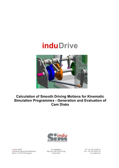
<strong>induDrive</strong><br />
Calculation of Smooth Driving Motions for Kinematic<br />
Simulation Programmes - Generation and Evaluation of<br />
Cam Disks<br />
induSim GmbH Geschäftsführer Tel. +49 7345 929287-0<br />
Centrum für industrielle Simulationen Dipl.-Ing., Dipl.-Wirtsch.-Ing. Fax. +49 7345 929287-50<br />
Benzstr. 15 D-89129 Langenau Georg Zeller www.indusim.de
Table of Contents<br />
Table of Contents ������������������������ ..���� 2<br />
What is <strong>induDrive</strong>? ����������������������� ����� 3<br />
First Step: Synthesis of Motion �������������������� .3<br />
Second Step: Analysis of the Contour ����������������� ..4<br />
<strong>induDrive</strong> Basic ����������������������������� 5<br />
Graphical Motion Design according to VDI 2143..������������� .5<br />
Graphic and Tabular Display of Motion Functions ������������ ..6<br />
Determining Curve Contours on the Basis of Synthesis Calculations ���� .7<br />
<strong>induDrive</strong> Result ���������������������������� ..7<br />
Advantages of <strong>induDrive</strong> at a Glance � .���������������� .� ..10<br />
page 2 / 11
What is <strong>induDrive</strong>?<br />
With the software tool <strong>induDrive</strong> kinematic<br />
simulation programmes are extended by the<br />
possibility to generate motion sequences<br />
without shock and jerk.<br />
Due to convenient operation and seamless<br />
integration into different CAD programmes the<br />
calculations during the construction process are<br />
carried out by the design engineer without<br />
special knowledge. Thus, e.g. cams and<br />
tappets can be constructed and optimized<br />
quickly.<br />
<strong>induDrive</strong><br />
offers the following kinematics laws according<br />
to VDI 2143:<br />
• rest<br />
• linear<br />
• 5th-degree polynomial<br />
• square parabola<br />
• modified trapezoid<br />
• modified sine<br />
• sine-linear-combination<br />
• harmonic combination<br />
• simple sine<br />
• inclined sine<br />
• spline<br />
• and others ...<br />
<strong>induDrive</strong><br />
can be integrated into the following<br />
simulation programmes:<br />
• visualNastran Motion<br />
• Dynamic Designer Professional for<br />
Solid Edge<br />
• Dynamic Designer Professional for<br />
Inventor<br />
• Cosmos Motion 2007<br />
• Soldiworks Motion 2009<br />
First Step:<br />
Synthesis of Motion<br />
A theoretical drive moving the elements<br />
exactly as requested is allocated to the<br />
output elements (e. g. tools in a<br />
packaging machine). By means of<br />
<strong>induDrive</strong> these motions can be preset,<br />
optimized and transferred to the<br />
simulation programme.<br />
For this so-called �motion design� many<br />
functions, auxiliary means and<br />
evaluations are available in <strong>induDrive</strong>.<br />
If the motion fulfils the requirements the<br />
model is completed by the kinematics<br />
tool up to the cam disk as far as this did<br />
not occur at an earlier time. The roller<br />
centre is followed up relatively to the<br />
rotating drive shaft, a trace curve (= centre path) is generated. This curve can be read into<br />
<strong>induDrive</strong> and directly transferred into the CAD programme, e. g. into a sketch. Thus, a curve<br />
contour which exactly fulfils the motion presetting can be deduced by an offset.<br />
page 3 / 11
Second Step:<br />
Analysis of the Contour<br />
Indeed, the contour generated by the<br />
synthesis can not always be realized: The<br />
curve contour may be too steep, may cause<br />
clamping or even cut itself. Therefore, an<br />
analysis of the contour is absolutely<br />
necessary.<br />
Initially, <strong>induDrive</strong> statically analyses the<br />
curve contour and evaluates it with respect<br />
to the gradient and radii of curvature.<br />
Following the kinematics in the simulation<br />
programme is �reversed�, i. e. driving<br />
actually takes place by the generated curve<br />
contour, the forces of the joints are<br />
measured.<br />
construction<br />
simulation<br />
Blister machine of Messrs. Somatec<br />
Due to the fact that the masses and the appropriate moments of inertia are known to the 3D<br />
construction, e. g. the Hertzian stress can directly be determined on the basis of the contact<br />
forces, dependent on the driven velocities. Analyses of limiting value can be carried out.<br />
For an efficient and optimal drive layout a close<br />
connection between construction and simulation<br />
is essential.<br />
page 4 / 11
<strong>induDrive</strong> Basic<br />
In the kinematics programmes drives can be defined. Functions can be indeed entered in a<br />
limited extent. But, if the requested function consists of different sections their definition via<br />
functional terms with distinction of cases gets rapidly very complex and error-prone due to<br />
that.<br />
Graphical Motion Design according<br />
to VDI 2143<br />
<strong>induDrive</strong> closes this gap. By means of<br />
a graphic function editor it is possible<br />
to define motion functions in sections<br />
according to VDI 2143.<br />
All laws of these guidelines are<br />
supported. Marginal values thereby are<br />
exchanged with the following, but also<br />
with the previous section.<br />
Input mask: entering of the kinematics laws<br />
graphically or in table form.<br />
Drive unit of a weaving machine of Messrs. Griffith Textile,<br />
England<br />
One example: A linear segment is completely<br />
ascertained by its initial point and its endpoint.<br />
Now, a following fifth-degree polynomial gets<br />
automatically the velocity of the linear segment<br />
at the beginning.<br />
This adaptation also occurs vice versa: A<br />
polynomial preceding the linear segment gets<br />
the velocity of the linear segment as the final<br />
velocity. That way the consistency of the first<br />
and second derivation is automatically<br />
assured.<br />
page 5 / 11
Graphic and Tabular Display of Motion Functions<br />
The calculated function (including derivations) is displayed graphically, but also in table form<br />
(depending on how it is transferred into the respective kinematics programme).<br />
Furthermore, the extremum of function and derivation is determined automatically. The<br />
function course is clearly graphically displayed and can easily be evaluated. In the diagrams<br />
graphical editing is possible. This facilitates the optimization of function courses<br />
considerably.<br />
The centre curve is transferred from the simulation<br />
as a scatter plot. It can be transmitted both<br />
as a spline into CAD systems generating the<br />
geometry and into <strong>induDrive</strong> Result evaluating the<br />
contour.<br />
<strong>induDrive</strong> Basic offers the possibility for<br />
administrating several functions in different<br />
editor windows. The visualization and<br />
adaptation of these functions occur in a<br />
common diagram.<br />
The transfer of <strong>induDrive</strong> data into the<br />
kinematics programme occurs via direct<br />
interface (API).<br />
All degrees of freedom of the ongoing model<br />
are displayed and selected for the<br />
calculation via <strong>induDrive</strong>. A simulation with<br />
new defined drives can directly be carried<br />
out.<br />
Several functions of motion can clearly be viewed at<br />
<strong>induDrive</strong><br />
has a direct interface to the following CAD<br />
programmes:<br />
• Inventor<br />
• Solid Edge<br />
• <strong>SolidWorks</strong><br />
Curve contours can be read into all other<br />
CAD programs only via DXF interface.<br />
page 6 / 11
<strong>induDrive</strong><br />
is suitable for generating of:<br />
• plane curve contours<br />
• three-dimensional cylinder<br />
curves or similar drives<br />
• slotted links<br />
and for programme presetting for<br />
electronic drives.<br />
Determining Curve Contours on the Basis of<br />
Synthesis Calculations<br />
Following to the calculation in the kinematics tool<br />
the positions of the roller centre are measured<br />
relatively to the rotating drive shaft and curve<br />
blank respectively and are automatically<br />
transferred into <strong>induDrive</strong>.<br />
The points can directly be transferred into some<br />
CAD systems via API interface, e. g. as a spline<br />
into a sketch. The real contour can directly be<br />
generated by an offset.<br />
For further CAD systems the data are saved as ASCII data and imported into the CAD<br />
system or exported as a DXF file and again imported into any CAD system (the module<br />
<strong>induDrive</strong> Result offers this possibility).<br />
<strong>induDrive</strong> Result<br />
After carrying out a curve synthesis the generated<br />
curve course must be analysed. For this purpose<br />
the scatter plot transferred from the kinematics<br />
tool is converted into a curve course (only for<br />
plane cam discs) by means of a circular<br />
interpolation (= circular arcs tangentially merged<br />
into each other). By an offset the �hard� curve<br />
contour can be generated also in this case.<br />
The position of the articulated joints of levers or<br />
tappets is automatically transferred from the<br />
kinematics tool - relatively to the cam disc - into<br />
<strong>induDrive</strong> Result. By these data the transmission<br />
angle between roller and curve contour is<br />
determined and displayed.<br />
Exemplary drive of 2 addicted axes<br />
page 7 / 11
Circular interpolated curve contours can be evaluated by<br />
means of <strong>induDrive</strong> Result.<br />
The coefficient of curvature and the transmission angle are<br />
displayed.<br />
Extensive auxiliary means provide<br />
information on the course of the<br />
gradient angle onto the curve<br />
contour. Problem areas are<br />
analysed.<br />
Due to the close interaction of the<br />
individual programme modules<br />
modifications can be carried out in<br />
a rapid, efficient and goal-oriented<br />
way no matter whether they are of<br />
geometrical type or in the definition<br />
of the functions of motion.<br />
Simulation and construction work<br />
are closely connected with each<br />
other.<br />
The contour generated by<br />
<strong>induDrive</strong> Result via circular<br />
interpolation can be saved as a<br />
DXF file and directly read into NC<br />
systems by a DXF interface.<br />
In order to facilitate the handling of<br />
NC programmes the number of arcs<br />
can be reduced: The contour has a<br />
preset tolerance limit (e. g. 0,01<br />
mm). Therewith, a lot of very small<br />
circular arcs can be combined into a<br />
bigger circular arc, which means a<br />
facility in particular for older<br />
controls.<br />
Via <strong>induDrive</strong> Basic curve contours can be modified and transmitted into CAD programmes.<br />
Therewith, the effect of manually modified curves on the mechanism can be analysed.<br />
page 8 / 11
Curve contours can purposefully be modified and<br />
tested. Transmission functions need not to be known.<br />
Circular interpolated curve contours can directly be<br />
read into CAD sketches.<br />
The circular interpolated paths can be<br />
exported into excel, entered as DXF file and<br />
are thus accessible to other CAD or NC<br />
programmes.<br />
<strong>induDrive</strong> can be used in connection with<br />
the operating systems<br />
• Windows NT<br />
• 2000<br />
• XP<br />
and works bilingually in German and<br />
English, depending on the language of the<br />
operating system.<br />
<strong>induDrive</strong><br />
requires the following from your<br />
system:<br />
• Operating system: Windows<br />
2000, XP<br />
• Hardware: commercial CAD<br />
processor<br />
• Memory requirements: approx.<br />
20 MB<br />
page 9 / 11
Advantages of <strong>induDrive</strong> at<br />
a Glance<br />
Optimized Construction: Due to<br />
optimized functions of motion stress of<br />
the machine components and noise<br />
development are<br />
reduced � efficiency and life-time of the<br />
machine increase.<br />
Reduction of Development Time: The<br />
system is already dynamically tested on<br />
the basis of the simulation model. First<br />
experiences regarding functionality can<br />
be made. The generated cam<br />
geometries usually work straight away.<br />
Time-consuming and non-documented<br />
modifications of cam discs are not<br />
necessary anymore. The machine is<br />
faster ready for use.<br />
Exemplary drive of a controlled linear motion<br />
Reduction of Construction Expenditure: Manual calculations, e. g. of motion functions or<br />
transmission angles, will be dismissed. Accelerations etc. are calculated without complete<br />
simulation of models. The direct data exchange reduces many sources of error.<br />
Reduction of Assembly Costs: Due to increased accuracy of construction necessary<br />
adjustment work during the assembly and consequently the assembly costs are reduced.<br />
page 10 / 11
Increase in Creativity and Productivity:<br />
Complex mechanisms are more comprehensible � extensions, improvements or alternatives<br />
which were a victim of lack of time can now be carried out.<br />
simulation programme<br />
e. g.<br />
Dynamic Designer ,<br />
Solidworks Motion<br />
CAD<br />
indu Drive<br />
calculation programme for smooth -<br />
motion<br />
program<br />
calculates drives<br />
evaluates curve contours<br />
describes the connections<br />
for dynamic<br />
multi-body simulation<br />
determines all geometric data<br />
Interaction of different programmes for calculating cam discs.<br />
Ask for further information on <strong>induDrive</strong>:<br />
induSim GmbH<br />
Centrum für industrielle Simulationen<br />
Benzstraße 15<br />
89129 Langenau<br />
Managing Director: Georg Zeller<br />
Phone ++ 49 (0) 7345 / 929287-0<br />
Fax ++49 (0) 7345 / 929287-50<br />
www.indusim.de<br />
georg.zeller@indusim.de<br />
page 11 / 11