Andris Lux Eco - UK Manual

You also want an ePaper? Increase the reach of your titles
YUMPU automatically turns print PDFs into web optimized ePapers that Google loves.
Unvented water heater
62<br />
“Enactment of Directive 2012/19/EU governing electrical and electronic waste (WEEE)”<br />
The barred bin symbol on the appliance and its packaging indicates that the product must be scrapped separately from other waste at<br />
the end of its service life. The user must therefore hand the equipment over to a sorted waste disposal facility for electro-technical and electronic<br />
equipment at the end of its service life.<br />
Alternatively, he may return the equipment to the retailer at the time of purchase of a new equivalent type of appliance. Electronic equipment of size less than<br />
25 cm can be handed over to any electronics equipment retailer whose sales area is at least 400 m2 for disposal free of charge and without<br />
any obligation to purchase new product.<br />
Sorted waste collection for recycling, treatment and environmentally compatible scrapping contributes to the prevention of damage to the<br />
environment and promotes reuse/recycling.<br />
3
GENERAL SAFETY INSTRUCTIONS<br />
CAUTION!<br />
1. This manual is an integral part of the product. Keep it with care<br />
with the appliance, and hand it on to the next user/owner in<br />
case of change of property.<br />
2. Read the instructions and warning in this manual carefully,<br />
they contain important information regarding safe installation,<br />
use and maintenance.<br />
3. The appliance must be installed and commissioned by a qualified<br />
technician in accordance with local legislation and health and safety<br />
regulations. All power circuits must be shut off before you open the<br />
front panel and access the electrical components.<br />
4. DO NOT use the appliance for any other than its specified use. The<br />
manufacturer is not liable for damage resulting from improper or<br />
incorrect use or failure to observe the instructions given in this<br />
manual.<br />
5. Incorrect installation can result in damage to property and injury to<br />
persons and animals; the manufacturer is not liable for the<br />
consequences.<br />
6. DO NOT leave the packaging materials (staples, plastic bags,<br />
expanded polystyrene, etc.) within the reach of children - they can<br />
cause serious injury.<br />
7. The appliance may not be used by persons under 8 years of age,<br />
with reduced physical, sensory or mental capacity, or lacking the<br />
requisite experience and familiarity, unless under supervision or<br />
following instruction in the safe use of the appliance and the hazards<br />
attendant on such use. DO NOT permit children to play with the<br />
appliance. User cleaning and maintenance may not be done by<br />
unsupervised children.<br />
8. DO NOT touch the appliance when barefoot or if any part of your<br />
body is wet.<br />
9. Any repairs, maintenance, plumbing and electrical connection must<br />
be done by qualified technicians using original spare parts only.<br />
Failure to observe the above instructions can compromise the safety<br />
of the appliance and relieves the manufacturer of any liability for the<br />
consequences.<br />
10. The hot water temperature is regulated by a thermostat which also<br />
acts as a resettable safety device to prevent dangerous overheating.<br />
11. The electrical connection must be done as indicated in this manual.<br />
12. If the appliance is equipped with a power cord, the latter may only<br />
be replaced by an authorised service centre or professional technician.<br />
13. Do not tamper with the overpressure safety device, if supplied<br />
4
together with the appliance; trip it from time to time to ensure that<br />
it is not jammed and to remove any scale deposits. In countries<br />
which have enacted EN 1487, the appliance's intake pipe must be<br />
equipped with a safety device compliant with the said standard,<br />
calibrated to a maximum pressure of 0.7 MPa, including at least a<br />
cock, check valve, safety valve and hydraulic load cutout.<br />
14. It is normal that water drip from the overpressure safety device and<br />
EN 1487 safety unit when the appliance is heating. For this reason<br />
one must install a drain, open to the air, with a continuously<br />
downwards sloping pipe, in an area not subject to subzero<br />
temperatures. Make sure to drain the appliance when it is out of<br />
service or in an area subject to subzero temperatures.<br />
15. Make sure to drain the appliance when it is out of service or in an<br />
area subject to subzero temperatures.<br />
16. Water heated to over 50° C can cause immediate serious burns if<br />
delivered directly to the taps. Children, disabled persons and the<br />
aged are particularly at risk. We recommend installing a thermostatic<br />
mixer valve on the water delivery line, marked with a red collar.<br />
17. Do not leave flammable materials in contact with or in the vicinity<br />
of the appliance.<br />
5
Symbols:<br />
Symbol<br />
!<br />
Meaning<br />
Failure to observe this warning can result in injury, which may even be fatal in certain<br />
circumstances<br />
Failure to observe this warning can result in damage or injury, even serious in certain circumstances,<br />
to property, plants and animals<br />
!<br />
Observe the product's general and specific safety instructions.<br />
GENERAL SAFETY STANDARDS<br />
Ref.<br />
Warning<br />
Risk<br />
Symbol<br />
1<br />
Do not open the appliance or remove from<br />
its installation<br />
Electrocution hazard due to the presence of live<br />
electrical equipment Personal injury - burns<br />
caused by overheated components and wounds<br />
caused by sharp edges<br />
!<br />
2<br />
Do not start or stop the appliance by inserting/pulling<br />
the power plug<br />
Electrocution hazard due to damage to the<br />
power cord, its plug or the socket<br />
!<br />
3 Do not damage the power cord<br />
Electrocution hazard due to bare live wires<br />
!<br />
4<br />
Do not leave objects on the appliance<br />
Personal injury due to objects falling off the<br />
appliance as a result of vibration<br />
Damage to the appliance or other property<br />
due to objects falling off the appliance as a<br />
result of vibration<br />
!<br />
5<br />
Do not climb onto the appliance<br />
Personal injury due to falling off the appliance<br />
Damage to the appliance or other property due<br />
to the appliance itself detaching from its mounting<br />
!<br />
6<br />
Do not clean the appliance without having<br />
first switched it off, pulled its power plug or<br />
shut off its power switch<br />
Electrocution hazard due to the presence of live<br />
electrical equipment<br />
!<br />
7<br />
Install the appliance to a solid wall which is not<br />
subject to vibration<br />
Danger of the appliance falling off the wall due<br />
to structural collapse, or noisy operation<br />
!<br />
8<br />
Make the electrical hookup with cables of<br />
adequate cross-section<br />
Danger of fire due to overheating of<br />
undersized electrical wires<br />
!<br />
9<br />
Restore all safety and control functions after<br />
working on the appliance and check that they<br />
are operational before returning it to service<br />
Damage or blocking of the appliance due to<br />
improper control<br />
!<br />
10<br />
Drain all components containing hot water, using<br />
the bleed cocks, before handling them<br />
Danger of burns<br />
!<br />
11<br />
Descale the system as given in the product's<br />
“safety sheet”; when doing so, ventilate the room,<br />
wear safety clothing, make sure not to mix<br />
products, and protect the appliance itself and<br />
any adjacent objects<br />
Personal injury due to contact of the skin and<br />
eyes with acid, inhalation or ingestion of noxious<br />
chemicals<br />
Damage to the appliance and adjacent objects<br />
due to corrosion by acid<br />
!<br />
12<br />
Do not use insecticides, solvents or aggressive<br />
detergents to clean the appliance<br />
Damage to plastic and painted parts and<br />
assemblies<br />
6
Anti-legionella recommendations (European standard CEN/TR 16355)<br />
Information<br />
Legionella is a small bacterium, of stick-like form, and is found naturally in fresh water.<br />
Legionnaire's disease is a serious pulmonary infection caused by inhalation of the Legionella pneumophilia bacterium and<br />
other species of Legionella. The bacterium is frequently to be found in the plumbing of houses, hotels and water used in A/C<br />
and air cooling systems. The most effective measure against infection is to prevent the bacterium proliferating in water circuits.<br />
European standard CEN/TR 16355 provides guidelines for preventing the proliferation of Legionella in drinking water systems,<br />
without substituting applicable local legislation.<br />
General recommendations<br />
“Conditions favourable to the proliferation of Legionella”. The following conditions are favourable to the proliferation of<br />
Legionella:<br />
• Water temperature in the range 25 - 50 °C. To reduce the proliferation of Legionella, the water temperature be kept with<br />
these limits to prevent them growing or reduce their growth to a minimum. If this is not possible, the drinking water<br />
system must be sanitised thermally;<br />
• Stagnant water. To prevent water stagnating for a long time, the drinking water system must be flushed or made to run<br />
abundantly at least once a week;<br />
• Nutrients, biofilms and sediment in the circuit, including boilers, etc. Sediment may promote the proliferation of Legionella<br />
and should be regularly eliminated from water storage devices, boilers and expansion/holding tanks (for instance, once<br />
a year).<br />
As regards storage heater like the present, if:<br />
1) the appliance is switched off for several months at a time or<br />
2) the water temperature is kept constant in the range 25 - 50°C,<br />
the Legionella bacterium may grow inside the tank. If such circumstances, to reduce the proliferation of the bacterium, one<br />
must run a thermal sanitisation cycle.<br />
This cycle is suited to use in domestic hot water systems and complies with the guidelines for the prevention of Legionella<br />
given in Table 2 of standard CEN/TR 16355 (see below).<br />
Ref. in<br />
Enclosure C<br />
Temperature<br />
Stagnation<br />
Sediment<br />
Separate hot and cold water<br />
No<br />
storage<br />
No<br />
circulation<br />
of hot water<br />
C.1<br />
-<br />
-<br />
-<br />
Circulation<br />
of hot water<br />
Table 2 - Types of hot water system<br />
No<br />
circulation<br />
of mixed<br />
water<br />
Storage<br />
Circulation<br />
of mixed<br />
water<br />
No storage<br />
upline of the<br />
mixer valves<br />
No<br />
circulation<br />
of mixed<br />
water<br />
Mixed hot and cold water<br />
Circulation<br />
of mixed<br />
water<br />
C.2 ≥ 50 °C e<br />
C.3<br />
in<br />
C.4<br />
≥ 50 °C e<br />
C.5<br />
thermal<br />
C.6<br />
thermal<br />
storage<br />
disinfection d disinfection d<br />
heater a<br />
≤ 3 l b<br />
-<br />
≤ 3 l b<br />
-<br />
- remove c remove c -<br />
≤ 3 l b<br />
-<br />
Storage upline<br />
of the mixer<br />
valves<br />
No<br />
circulation<br />
of mixed<br />
water<br />
C.7<br />
in<br />
storage<br />
heater a<br />
-<br />
remove c<br />
Circulation<br />
of mixed<br />
water<br />
C.8<br />
≥ 50 °C e<br />
thermal<br />
disinfection d<br />
≤ 3 l b<br />
remove c<br />
No storage<br />
upline of the<br />
mixer valves<br />
No<br />
circulation<br />
of mixed<br />
water<br />
C.9<br />
Circulation<br />
of mixed<br />
water<br />
thermal thermal<br />
disinfection d disinfection d<br />
-<br />
-<br />
C.10<br />
≤ 3 l b<br />
a Temperature ≥ 55°C all day or at least 1h a day ≥60°C.<br />
b Volume of water contained in the pipes between the circulation system and the most distant tap.<br />
c Remove the sediment from the storage heater as required by local conditions, but no less frequently than once a year.<br />
d Thermal disinfection for 20 minutes at 60°C, for 10 minutes at 65°C or 5 minutes at 70 °C at all delivery points at least once<br />
a week.<br />
e The water temperature in the circulation circuit may not fall below 50°C.<br />
- Not required<br />
-<br />
This storage water heater is sold with a thermal disinfection cycle function not enabled for default; as a consequence, if, for<br />
any reason, one of the above said “Conditions for Legionella growth” could occur; it’s hardly recommended to enable such<br />
function rotating the knob up to maximum water temperature (>60°C).<br />
However, the thermal disinfection cycle does not kill all Legionella bacteria in the storage tank. It follows that if the water<br />
temperature setting is less than 55°C, the Legionella bacterium infection may reoccur.<br />
Caution: the water temperature in the tank can cause immediate serious burns. Children, disabled persons and the aged<br />
are particularly at risk of burns. Check the water temperature before taking a bath or shower.<br />
7
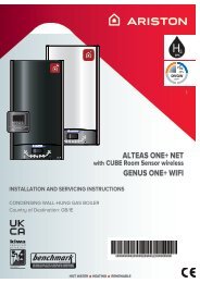
Description of water heater<br />
4<br />
1) Hot water outlet (1/2” male BSP)<br />
2) Temperature and pressure relief valve (30 litre only)<br />
3) Cold water inlet (1/2” male BSP)<br />
4) Control cover<br />
5) Regulation Keyboard<br />
6) Heating Led<br />
5<br />
2<br />
4<br />
5 6<br />
1 3<br />
Over-sink (10/15 OR)<br />
5<br />
1 3<br />
4<br />
1 3<br />
Over-sink (30)<br />
6<br />
Under-sink (10/15 UR)<br />
TECHNICAL SPECIFICATIONS<br />
For the technical specifications, refer to the nameplate (the nameplate is located next to the water intake/outlet pipes).<br />
6<br />
8
The power consumption data in the table and the other information given in the Product Data<br />
Sheet (Enclosure A to this manual) are defined in relation to EU Directives 812/2013 and<br />
814/2013.<br />
Products equipped with regulator knobs have the thermostat positioned in the setting<br />
condition at its set position shown in the Data Sheet (Enclosure A), used by<br />
the manufacturer to declare the appliance's energy class.<br />
This appliance is conforming with the international electrical safety standards IEC<br />
60335-1 and IEC 60335-2-21.<br />
The CE marking of the appliances attests its conformity to the following EC Directives,<br />
of which it satisfies the essential requisites:<br />
- LVD Low Voltage Directive: EN 60335-1, EN 60335-2-21, EN 60529, EN 62233, EN 50106.<br />
- EMC Electro-Magnetic Compatibility: EN 55014-1, EN 55014-2, EN 61000-3-2, EN<br />
61000-3-3.<br />
- RoHS2 Risk of Hazardous Substances: EN 50581.<br />
- ErP Energy related Products: EN 50440.<br />
- EN 12897:2006<br />
Water Regulations and Byelaws<br />
These regulations and byelaws ensure a good supply of wholesome water, and that<br />
only approved materials, pipes and fittings are used to convey water.<br />
Building Regulations<br />
These are a statutory document and take priority over all other regulations and<br />
recommendations. The installation of an unvented hot water system of over 15 litres<br />
is classified as a “Controlled Service” and Regulation G3 applies. To meet the<br />
requirements of the regulation, installation of an unvented system should be<br />
undertaken by a “competent installer”.<br />
All installations of unvented hot water storage systems having a capacity of more than<br />
15 litres should be notified to the relevant Local Authority by means of building notice<br />
or by the submission of full plans. It is important to note that it is a criminal offence to<br />
install an unvented hot water storage system over 15 litres without notifying the Local<br />
Authority.<br />
Delivery<br />
The products are supplied with the following:<br />
Unvented water heater (with factory-fitted T&P model 30L)<br />
Wall bracket<br />
Pressure relief valve set at 6 bar<br />
Dielectric junctions<br />
Tundish (model 30L only)<br />
Expansion Vessel (model 30L only)<br />
Check Valve (model 30L only)<br />
Pressure reducing Valve (model 30L only)<br />
x1<br />
x1<br />
x1<br />
x2<br />
x1<br />
x1<br />
x1<br />
x1<br />
9
Important note: Dielectric junctions must be fitted to all models as they prevent an<br />
electrolytic reaction and safeguard against potential aggressive corrosion.<br />
User instructions<br />
Recommendations<br />
- Do not place anything under the water heater which may be damaged by a leak.<br />
- If the water is not used for a long time:<br />
➣ shut off power to the appliance by setting the external switch to "OFF";<br />
➣ close the water circuit cocks.<br />
- Water heated to over 50C can cause immediate serious burns or even death.<br />
Children, disabled persons and the aged are particularly at risk of burns.<br />
Do not attempt to service or repair the appliance.<br />
Reset/Diagnostics<br />
When any of the faults described below occurs, the device goes into fault status and<br />
all the LEDs on the control panel flash simultaneously.<br />
Reset: reset the appliance by switching it off and on from the key (A fig.6). If the cause<br />
of the fault disappears when reset, the appliance resumes its regular operation.<br />
Otherwise, all the LEDs start to flash again and Technical Assistance must be<br />
requested to intervene.<br />
Diagnostics: activate the diagnostics by pressing the key (A fig.6) for 5 seconds.<br />
The indication of the type of fault is provided via 5 led (1➔5 fig.6) according to the<br />
following diagram:<br />
LED ref. 1 – Fault inside the board;<br />
LED ref. 2 - Fault at the anode (in models with an active anode);<br />
LED ref. 3 - Faulty NTC 1/NTC 2 temperature sensors (open or short circuited);<br />
LED ref. 5 - Water over temperature detected by a single sensor;<br />
LED ref. 4 and 5 - General over temperature (board failure);<br />
LED ref. 3 and 5 - Probe differential error;<br />
Exit the diagnostics by pressing the key (A fig.6) or wait 25 s.<br />
Activating the "thermal disinfection cycle" (anti-legionella)<br />
The product has the "thermal disinfection cycle" disabled by default.<br />
The activation of the "thermal disinfection cycle" is displayed as a normal temperature<br />
setting at 60°C.<br />
Activate this function by pressing and holding both the "ECO" and "+" keys for 4 s.;<br />
once activation is confirmed, LED 60 will flash quickly for 4 s.<br />
Permanently deactivate the function by repeating the above steps; once the<br />
deactivation is confirmed, LED 40 will flash quickly for 4 s.<br />
Adjusting the temperature and activating the functions of the device<br />
Switch the device on by pressing the key (A fig.6). Set the desired temperature by<br />
selecting a level between 40°C and 80°C using the ”+” and “-“ buttons. During the<br />
heating phase, the LEDs (1➔5 fig.6) related to the temperature reached by the water<br />
remain on; the subsequent ones until the temperature is set, flash progressively. If the<br />
temperature drops, for example due to water being drawn, the heating is automatically<br />
reactivated and the LEDs between the last one on (steady) and that related to the set<br />
10
temperature start to flash progressively again.<br />
When first switched on, the product is set to 70°C.<br />
In case of a power failure or if the product is switched off using the button (A fig.6),<br />
the last temperature set remains saved.<br />
Slight noise may occur during the heating phase due to the water being heated.<br />
ECO EVO function<br />
The "ECO EVO" function consists of self-learning software of the user consumption,<br />
which allows heat loss to be minimised and energy savings to be maximised. This<br />
function is active by default.<br />
The "ECO EVO" software consists of an initial learning period of a week when the<br />
product begins to operate at the temperature indicated in the product data sheet<br />
(Attachment A) and logs the user energy demand. From the second week onwards<br />
the learning process continues so as to learn the user requirements in more detail and<br />
changes the temperature every hour to adapt it to the actual demand in order to<br />
improve energy savings. The "ECO EVO" software activates the heating of the water<br />
within the time and amounts determined automatically by the product itself according<br />
to user consumption. During the day, when no water is drawn, the product still<br />
guarantees a reserve of hot water.<br />
Activate the "ECO" function by pressing the relevant key that lights up green.<br />
Two operating modes are possible:<br />
1) <strong>Manual</strong> adjustment of the temperature (see the "Adjusting the temperature and<br />
activating the functions of the device" paragraph): the manual mode is accessed with<br />
the ECO button off. In this mode, the product continues to note the user's energy<br />
demand without adjusting the temperature selected by the user. Press the "ECO" key<br />
for it to light up and the "ECO EVO" function to start, which is immediately effective in<br />
this case as the "learning process" has already been implemented;<br />
2) ECO EVO:<br />
- After the first week of continuous learning, the water heater always prepares the<br />
amount of hot water according to a statistical prediction of demand which is supplied<br />
in time: to do so, the temperature will be automatically determined which will always<br />
be between a Tminimum=40°C and a maximum temperature that is set by the user<br />
(by default, the maximum temperature is equal to the value shown in the data sheet<br />
[Attachment A])<br />
- Press the ECO key for long for the eco LED to flash for about 4 s and the learning<br />
process restarts (from the first week). This is used to delete the user demand from the<br />
memory and restart (hard reset).<br />
- Caution: when the ECO key is on and the "+/-" keys (Fig.6) or the knob (Fig.6) or the<br />
"ECO" key itself are pressed, the <strong>Eco</strong> soft mode described above is accessed (the<br />
ECO key goes off).<br />
In order to guarantee proper ECO operation, it is recommended not to disconnect the<br />
product from the mains.<br />
Anti-limescale Function:<br />
If much limescale is detected, the product switches to limited mode, which is actually<br />
"manual" mode with the heating temperature set to 65°C and the ECO SMART<br />
function disabled.<br />
Warning: the first 3 heating LEDs flash simultaneously (Fig.6➔1;2;3)<br />
11
Installation instructions<br />
Before installing the heater read these instructions in full. If you are unsure please<br />
contact our technical service department (03332407777).<br />
12<br />
Note: For further information please refer to the flow chart on page 19 which gives<br />
guidance on choosing controls.<br />
The installation must comply with all relevant Water Regulations/Byelaws and<br />
Building Regulations.<br />
The installer should check with the local water authority for confirmation of the<br />
maximum water supply pressure.<br />
a) SITING & FIXING WARNING:<br />
The appliance should be left packed until it is ready to be installed. When<br />
unpacking the 30 L model take care not to damage the temperature and pressure<br />
relief valve on the top of the heater.<br />
A drain has to be provided for any water discharged through the safety valves.<br />
Access to the heater is not normally needed on a day-to-day basis, but 300mm clearance<br />
to the front of the water heater sould be kept for servicing and maintenance<br />
A cold water supply pressure between 1 and 3.5 bar is required (if the mains pressure is<br />
above 3.5 bar a pressure reducing valve must be installed). Please note that turning<br />
down the stop-cock will reduce flow not pressure.<br />
The outlet pressure from the reducing valve (if supplied) is 3.5 bar.<br />
A 240 VAC; 3 kW single phase electrical supply is required.<br />
Position the heater against the wall and mark the position of the hooked<br />
wall bracket. Fasten the wall bracket to wall using suitable screws and wall plugs (ensure<br />
that wall is suitable to support the unit, allowing for the extra weight of water when it is<br />
full). Hang the heater on the bracket making sure that the heater is pulled well down on<br />
to the bracket, if necessary by forcing the hooks into the foam insulation.<br />
Ensure the unit is accessible and maintains sufficient clearances to allow for service and<br />
maintenance.<br />
Ensure the unit is installed in a place where freezing will not occur.<br />
Ensure a suitable low level drain off cock is installed on the hot and cold plumbing system.<br />
b) PLUMBING WARNING:<br />
Note: If a valve i.e. a non return valve, water meter, pressure reducing valve or any<br />
type of valve or fitting that acts as a non return valve is installed on the cold water<br />
mains, this will prevent expansion. Therefore it will be necessary to install an<br />
expansion vessel (see pages 12&13 figs 2 & 3).<br />
Note: If in doubt always install a pressure reducing valve (limited to 3.5bar) and<br />
expansion vessel.<br />
The outlet from temperature and pressure relief valve/pressure relief valve must<br />
not be for any other purpose.<br />
Take great care not to allow any swarf into the pipe work or fittings, as this might impair<br />
the operation of the safety valve(s).<br />
The water connection may be carried out as per the following:
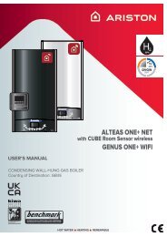
1) Using the feed pipe to accommodate expansion<br />
(Schedule 2, Section 6: Paragraph 15 of the Water Supply (Water Fittings)<br />
Regulations 1999 and the Water Byelaws 2000, Scotland) (Fig. 1).<br />
Fig. 1<br />
(Note this system is not<br />
suitable for 30L models)<br />
Do not fit any stop cocks or isolating valves within the distance required for expansion.<br />
If a pressure reducing valve is needed, due to a mains pressure of over 3.5 bar, an<br />
expansion control kit must be fitted regardless of expansion pipework installed. The<br />
expansion distances quoted are for 15mm pipes and can be approximately halved for<br />
22mm pipes.<br />
2) Using a set of expansion controls (Fig. 2 & 3).<br />
Fig. 2<br />
(Models 10L/15L)<br />
13
Fig. 3<br />
(Models 30L)<br />
The tundish must be installed away from electrical devices.<br />
The model 30L is covered under the Building Regulations and therefore it is not<br />
possible to accommodate the expansion water within the system pipe work and<br />
consequently a set of expansion controls must be installed.<br />
Note: The discharge from relief valves must be made in a safe and conspicuous<br />
manner; therefore a tundish (Kit C) is available for 10 and 15 litre units if required.<br />
Please note that in all cases the dielectric junctions must be connected to the<br />
heater before any other connection is made (these prevent an electrolytic<br />
reaction).<br />
Only the use of copper pipe is recommended for connection to the heater. If any<br />
other material is used it must be able to withstand 90°C at 7 bar pressure for<br />
long periods.<br />
No valve must be fitted between the expansion/pressure relief valve and the<br />
water heater.<br />
All other required safety components to install the model 30L are supplied as a<br />
kit with the appliance:<br />
15mm pressure reducing valve set at 3.5bar.<br />
Expansion vessel (charge pressure set at 3.5bar)"<br />
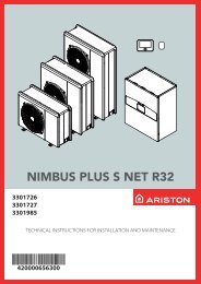
c) DISCHARGE PIPE WORK NOTE:<br />
The following guidelines refer to Building Regulation G3. It is good practice to<br />
follow these guidlines for all relief valve discharge pipe work.<br />
1) The tundish must be vertical and fitted within 600 mm of the temperature &<br />
pressure relief valve and must be located with the cylinder. The tundish must also be<br />
in a position visible to the occupants, and positioned away from any electrical devices.<br />
The discharge pipe from the tundish should terminate in a safe place where there is<br />
no risk to persons in the vicinity of the discharge and to be of metal.<br />
2) Discharge pipes from the temperature & pressure relief and pressure relief valve<br />
may be joined together.<br />
14
3) The pipe diameter must be at least one pipe size larger than the nominal outlet size<br />
of the safety device unless it’s total equivalent hydraulic resistance exceeds that of a<br />
straight pipe 9 m long.<br />
i.e. Discharge pipes between 9 m and 18 m equivalent resistance length should be at<br />
least 2 sizes larger than the nominal outlet size of the safety device. Between 18<br />
m and 27 m at least 3 times larger, and so on.<br />
Bends must be taken into account in calculating the flow resistance.<br />
See fig..5 and Table 2.<br />
4) The discharge pipe must have a vertical section of pipe at least 300 mm in length,<br />
below the tundish before any elbows or bends in the pipe work.<br />
5) The discharge pipe must be installed with a continuous fall.<br />
6) The discharge must be visible at both the tundish and the final point of discharge,<br />
but where this is not possible or practically difficult; there should be clear visibility at<br />
one or other of these locations. Examples of acceptance are:<br />
i) Ideally below a fixed grating and above the water seal in a trapped gully.<br />
ii) Downward discharges at a low level; i.e. up to 100 mm above external surfaces<br />
such as car parks, hard standings, grassed areas etc. These are acceptable providing<br />
that where children may play or otherwise come into contact with discharges, a wire<br />
cage or similar guard is positioned to prevent contact, whilst maintaining visibility.<br />
iii) Discharges at high level; i.e. into a metal hopper and metal down pipe with the<br />
end of the discharge pipe clearly visible (tundish visible or not). Or onto a roof capable<br />
Fig.. 4<br />
Suggest ways of terminating discharge pipes safely<br />
Temperature & pressure<br />
relief valve<br />
Metal discharge pipe (D1) from<br />
temperature & pressure relief valve.<br />
to tundish.<br />
600 mm Max.<br />
Tundish<br />
300 mm<br />
Min.<br />
Metal discharge pipe (D2) from tundish<br />
with continuous fall. See Table 2 and worked<br />
example.<br />
Discharge below<br />
fixed grating.<br />
(see page 6 for<br />
alternative points<br />
of discharge).<br />
Fixed grating<br />
Trapped gulley<br />
15
of withstanding high temperature discharges of water 3 m from any plastic guttering<br />
systems that would collect such a discharge (tundish visible).<br />
iv) Where a single pipe serves a number of discharges, such as in blocks of flats, the<br />
number served should be limited to not more than 6 systems so that any installation<br />
can be traced reasonably easily. The single common discharge pipe should be at least<br />
one pipe size large than the largest individual discharge pipe to be connected. If<br />
unvented hot water storage systems are installed where discharges from safety<br />
devices may not be apparent i.e. in dwellings occupied by the blind, infirm or disabled<br />
people, consideration should be given to the installation of an electronically operated<br />
device to warn when discharge takes place. Note: The discharge will consist of<br />
scalding water and steam. Asphalt, roofing felt and non-metallic rainwater goods may<br />
be damaged by such discharges.<br />
Table 2<br />
Sizing of copper discharge pipe “D2” for common temperature valve outlets.<br />
Valve outlet size<br />
Minimum size of<br />
discharge pipe D1*<br />
Minimum size of<br />
discharge pipe D2*<br />
from tundish<br />
G 1/2 15 mm 22 mm<br />
28 mm<br />
35 mm<br />
G 3/4 22 mm 28 mm<br />
35 mm<br />
42 mm<br />
G 1 28 mm 35 mm<br />
42 mm<br />
54 mm<br />
Maximum<br />
resistance allowed,<br />
expressed as a<br />
length of pipe (i.e.<br />
no elbow or bends)<br />
Up to 9 m<br />
Up to 18 m<br />
Up to 27 m<br />
Up to 9 m<br />
Up to 18 m<br />
Up to 27 m<br />
Up to 9 m<br />
Up to 18 m<br />
Up to 27 m<br />
Resistance created<br />
by each elbow or<br />
bend<br />
0.8 m<br />
1.0 m<br />
1.4 m<br />
1.0 m<br />
1.4 m<br />
1.7 m<br />
1.4 m<br />
1.7 m<br />
2.3 m<br />
Worked example<br />
The example below is for a G 1/2” temperature & pressure relief valve with a discharge<br />
pipe (D2) having 4 no. elbows and length of 7 m from the tundish to the point of<br />
discharge.<br />
From Table 2<br />
Maximum resistance allowed for a straight length of 22 mm copper discharge pipe<br />
(D2) from G 1/2” T & P valve is 9 m.<br />
Subtract the resistance for 4 no. 22 mm elbows at 0.8 m each = 3.2 m.<br />
Therefore the maximum permitted length equates to: 5.8 m.<br />
As 5.8 m is less than the actual length of 7 m therefore calculate the next<br />
largest size.<br />
Maximum resistance allowed for a straight length of 28 mm pipe (D2) from G 1/2” T &<br />
P valve equates to: 18 m.<br />
Subtract the resistance for 4 no. 28 mm elbow at 1.0 m each = 4 m.<br />
Therefore the maximum permitted length equates to: 14 m<br />
As the actual length is 7 m, a 28 mm (D2) copper pipe will be satisfactory.<br />
16
d) ELECTRICAL WARNING:<br />
The appliance must be earthed<br />
The electrical installation must be in line with the current I.E.E. wiring regulations.<br />
A mains supply of 240 VAC 3 kW (13 amps) is required (Fig. 5)<br />
Heat resisting cable, round 3 core 1.5 mm (to BS 6141 table 8) should be used to<br />
connect to the electrical supply through either:<br />
- a 13 amp socket to BS 1363; or<br />
- a double pole fused isolating switch with a contact separation of 3 mm minimum on<br />
each pole.<br />
The cable enters the terminal compartment through a tube embedded in the foam<br />
insulation, the entrance to this tube is on the rear right hand side at the bottom.<br />
Flexible cables are colour coded as follows:<br />
Brown.................................................. live<br />
Blue............................................... neutral<br />
Green and yellow............................. earth<br />
THERMAL<br />
CUT-OUT<br />
THERMOSTAT<br />
HEATING<br />
ELEMENT<br />
LED<br />
L<br />
N<br />
E<br />
Fig..5<br />
wiring diagram<br />
To enter into the terminal compartment unscrew the 2 screws on the cover.<br />
(To access the screws, remove the decorative caps on the front control access panel).<br />
e) COMMISSIONING<br />
- Check that all the necessary components are supplied and for those not factory<br />
fitted, that they are the type recommended by the manufacturer for the particular<br />
water heater.<br />
- Check that the water heater/components are undamaged.<br />
- Check that the discharge pipe is plumbed so that it falls continuously and that no<br />
taps, valves or other shut-off devices are installed in the pipe.<br />
17
- Check that the discharge pipe drains safely to waste and is readily visible.<br />
- Check, in the case where some components are not factory fitted, that they are<br />
marked so as to refer to the warning label on the water heater.<br />
- Open all outlet taps.<br />
- Turn on the mains water supply.<br />
- Close taps in turn as water flow stabilises with no air bubbles.<br />
- Check for leaks.<br />
- Check that no water is passing through the safety valve(s).<br />
- Test the operation of the safety valve(s) by lifting/turning the lever/knob, and<br />
observing that water flows through and safely to waste.<br />
- Switch on electricity and set thermostat to at 60°C to reduce the build up of scale<br />
in hard water areas.<br />
- Check the water heats up.<br />
- Check that is secure and visible on the heater and<br />
related warning labels are fitted to the controls.<br />
- Demonstrate operation to user, including operation of safety valve(s) and what to do<br />
if it/they operate(s).<br />
- Give this handbook to the user and discuss future maintenance.<br />
- Drain and refill the entire system ensuring it is flushed in accordance with BS6700.<br />
Fig. 6<br />
1 2 3 4 5<br />
T<br />
W<br />
Y<br />
A<br />
K<br />
G<br />
C<br />
M<br />
18
Maintenance<br />
a) For the user<br />
In order to obtain the best performance from the heater, the sacrificial anode must<br />
be checked every year and replaced as necessary. If the heating element is heavily<br />
coated with scale we recommend descaling and removing any lime deposit from the<br />
heater at the time of this inspection. Where the additional cold water controls are<br />
fitted, the expansion vessel will need to be recharged by the installer.<br />
Important note: The heater must be serviced annually. Failure to service which<br />
includes inspection and replacement of the sacrificial anode will invalidate<br />
warranty.<br />
b) For the installer<br />
WARNING: Switch off the power first<br />
Access to the electrical components, the magnesium anode and water container is<br />
gained by unscrewing the 2 screws on the front cover.<br />
If the thermal cut-out has operated the cause must be found before resetting.<br />
To drain the heater close the service valve and:<br />
i) for under-sink models disconnect pipes and removed the heater from the wall.<br />
ii) for over-sink models undo the cold water supply pipe and open a hot water tap.<br />
The heating element may be removed (after taking out the thermostat phials on<br />
model 30 L) by undoing the M6 nut.<br />
The assembly should then be turned through 90° anti-clockwise to ease removal<br />
from the water container.<br />
Once the element is free from the water container the anode may then be<br />
inspected and removed if necessary.<br />
When reassembling the cover make sure that the regulation knob is coupled with<br />
the thermostat.<br />
Check controls (where fitted) as per the following:<br />
- Line strainer - with the water supply turned off remove screen from strainer and<br />
clean of any detritus;<br />
- Expansion vessel - with the water supply turned off and taps open, check expansion<br />
vessel pressure and top up as necessary;<br />
- Temperature & pressure relief valve - with the water supply turned on, check<br />
manually by lifting the test lever/turning the test knob (ensure valve closes after<br />
testing);<br />
- Expansion relief valve - check manually by turning the test knob (ensure valve<br />
closes after testing);<br />
- Discharge pipes (D1) - from both temperature & pressure relief and expansion relief<br />
valve for obstructions;<br />
- Tundish & discharge pipe (D2)- open either valve gradually to produce a full bore<br />
discharge into tundish and D2 without any back pressure;<br />
- Pressure reducing valve - check that the correct outlet pressure is being maintained<br />
by recording the pressure at an in-line terminal fitting i.e. tap.<br />
19
Fault finding<br />
1) Pressure and temperature valve dripping/running all the time.<br />
Cause: Thermal cut-out and thermostat have failed (this is only the case if the<br />
water being discharged is near to boiling).<br />
Mains pressure is too high. A pressure reducing valve must be fitted (see fig. 3).<br />
2) Pressure relief valve dripping/running all the time.<br />
Cause: Mains pressure is above 3.5 bar. A pressure reducing valve must be fitted<br />
(see fig. 2).<br />
3) Dripping while unit heating.<br />
Cause: Not enough pipe work for expansion; or stop-cock, non-return valve or<br />
pressure reducing valve has been fitted on the cold mains supply (see fig. 2). If an<br />
expansion vessel has been fitted, the charge may have failed.<br />
4) No hot water.<br />
Cause: Thermal cut-out has operated.<br />
The heating element has burnt-out.<br />
The thermostat is faulty.<br />
5) Milky water.<br />
Cause: This is a result of heavily limed and oxygenated water being heated. This<br />
is harmless and the cause is the water or a loose jumper washer in the outlet<br />
tap and not the heater itself.<br />
6) No water at all.<br />
Cause: Valve incorrectly fitted.<br />
Debris in the mains.<br />
Mains water supply turned off.<br />
7) Grey metallic deposit in the water<br />
Cause:Corrosion of the sacrificial anode.<br />
(Note: Corrosion of the sacrificial anode is normal operation of the unit)<br />
8) Rapid depletion of the sacrifical anode (see 7)<br />
Cause: Di-electric junctions not fitted<br />
Water softener fitted on incoming supply to water heater<br />
(Softened will cause the anode to deplete more rapidly than hard water)<br />
Note Whilst Ariston do not advise against the use of water softener devices, the<br />
end user must be advised that rapid depletion of the sacrificial anode may<br />
occur as a result of the softened water which can result in metallic grey deposit<br />
in the water.<br />
20
The 10 and 15 litre capacity units can be installed in a number of ways.<br />
The following guidelines are designed to help the correct method prior to installation.<br />
21
WE MAKE USE OF<br />
RECYCLED PAPER<br />
Manufactured by:<br />
Ariston Thermo S.p.A.<br />
Viale Aristide Merloni, 45<br />
60044 Fabriano (AN)<br />
Tel. (+ 39) 0732 .6011<br />
ariston.com<br />
Commercial subsidiary:<br />
Ariston Thermo <strong>UK</strong> Ltd<br />
Artisan Building<br />
Hillbottom Road<br />
High Wycombe<br />
HP12 4HJ<br />
www.ariston.co.uk<br />
e-mail: info.uk@aristonthermo.com<br />
Customer Service: 0333 240 8777<br />
Technical Advice: 0333 240 7777<br />
420010720402 0716