OWNER'S MANUAL - Pool Heat Pumps
OWNER'S MANUAL - Pool Heat Pumps
OWNER'S MANUAL - Pool Heat Pumps

Create successful ePaper yourself
Turn your PDF publications into a flip-book with our unique Google optimized e-Paper software.
OWNER’S <strong>MANUAL</strong><br />
TABLE OF CONTENTS<br />
SAFETY CONSIDERATIONS 2<br />
INSPECTION 2<br />
GENERAL INFORMATION 2<br />
INSTALLATION 2<br />
WATER FLOW & CONNECTIONS 2-3<br />
ELECTRICAL CONNECTIONS 4<br />
MODES OF OPERATION 5<br />
WIRING DIAGRAMS 6<br />
ELECTRONIC CONTROL PANEL 7<br />
START-UP 8-9<br />
MAINTENANCE 9-10<br />
TROUBLESHOOTING CHECKLIST 10-11<br />
CALLING FOR SERVICE 11<br />
WARRANTY 12<br />
WARRANTY REGISTRATION 13<br />
31808 Executive Blvd<br />
Leesburg, FL 34748<br />
(352)314-2971<br />
Fax (352) 314-2977<br />
www.romeindustriesinc.com<br />
Manufacturing High Quality, High Efficiency<br />
<strong>Heat</strong> Pump <strong>Pool</strong> <strong>Heat</strong>ers<br />
1<br />
DOC.10108<br />
SOLARIUM<br />
SOLAR HEAT PUMP<br />
SERIES<br />
INSTALLATION,<br />
OPERATION,<br />
MAINTENANCE<br />
& SERVICE
SAFETY CONSIDERATIONS<br />
• Qualified personnel should perform installation, maintenance and service.<br />
• Make sure all field wiring conforms to the heater specifications and all national and local<br />
codes.<br />
• Disconnect all power sources before performing any maintenance or service to the heater.<br />
INSPECTION<br />
Immediately upon receipt, inspect cartons and their contents for damage due to transit.<br />
Damage, if found, should be noted on delivery papers and a claim filed with the carrier. Also,<br />
check unit data plate to make sure you have the proper model, before installing.<br />
GENERAL INFORMATION<br />
The information in this manual was prepared to assist in the proper installation, operation,<br />
maintenance and service of your new heat pump pool heater. Please read the entire manual<br />
and follow all instructions. Improper installation and use can result in damage to the heater,<br />
unsatisfactory operation, and may void the warranty. Retain this manual for quick reference.<br />
INSTALLATION<br />
When selecting a location consider the following:<br />
• <strong>Heat</strong>er must be located outdoors.<br />
• Minimum of 24” of clearance on access / service side of heater.<br />
• Minimum of 18” of clearance on all three air intake sides of heater.<br />
• Minimum of 48” of clearance for air discharge (top of unit).<br />
• The heater should sit on a solid level surface sufficient above grade to prevent water from<br />
entering it, and allowing condensate to drain from base.<br />
• The length of water piping and electric should be kept to a minimum to avoid capacity loss<br />
and decreased efficiency.<br />
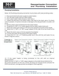
WATER FLOW & CONNECTIONS<br />
Water connections are made at the rear of the heater. Both water in and out are labeled<br />
at the connections. LEFT REAR = WATER IN and RIGHT REAR = WATER OUT.<br />
2” unions are supplied and are made to accept 2” rigid PVC pipe. NOTE: unions can be used<br />
for quick drainage of your heater and winterizing.<br />
• <strong>Heat</strong>er must be piped downstream from filter in the pool return line.<br />
• Inline chlorinators must be piped downstream from heater.<br />
• When all the plumbing connections are complete, and ample drying time is allowed, run the<br />
filter pump and check the entire system for water leaks.<br />
2
• Make sure filter is clean and there are no obstructions in the filtering system.<br />
• Proper water flow is essential to the performance of your heater.<br />
• The minimum flow rate is 20 GPM.<br />
TYPICAL WATER FLOW CONNECTIONS<br />
3
ELECTRICAL CONNECTIONS<br />
Field connections must comply with national and local codes. The work must be done by a qualified<br />
electrician.<br />
<strong>Heat</strong>er must be permanently grounded and bonded.<br />
Bonding will drastically reduce the chances of electrolysis, “Electrical Corrosion.”<br />
Use copper conductors only.<br />
Disconnect all power sources before performing any work on unit.<br />
Standard Power Supply: 208/230 - 60 - 1<br />
See unit data plate for specific ampacity.<br />
Wiring Main Power Supply<br />
1. Remove the screws from lower left and right side of front cover (service panel).<br />
2. Remove the screws on left side of hinged electrical enclosure.<br />
3. Route weather tight flexible conduit through opening at base of unit. Connect conduit to<br />
back of the electrical enclosure using a weather tight fitting. A knockout is provided next to the<br />
main contactor to accept the weather tight fitting. Mounting conduit directly to the electrical<br />
enclosure will ensure a moisture tight seal, extending the life of the heater.<br />
4. Attach grounding conductor to the ground lug provided inside the electrical enclosure (labeled).<br />
5. Install L1 and L2 input conductors to the line side of the main contactor. (See wiring diagrams.)<br />
6. Connect bond wire (at least #8 solid copper wire) from bond lug provided on right or left side of<br />
coil header plate to pool pump bonding terminal or other suitable location.<br />
4
MODES OF OPERATION<br />
To Change Between <strong>Pool</strong> and Spa Set Points Automatically:<br />
This change can be done automatically as the water flow is either directed to the pool or spa. The use<br />
of an external water pressure switch in the spa piping IS necessary. A two-wire control circuit must<br />
be connected from the water pressure switch to terminals P/S on the electronic control board.<br />
Remote Thermostats and Controllers:<br />
If a remote thermostat or any other control system is to be used to turn the heater on and off, a normally<br />
Open dry contact can be made at terminals P/S on the bottom right of the electronic control board.<br />
In the case of a remote thermostat where the temperature will be regulated externally, set the <strong>Pool</strong> Mode<br />
to the OFF position and the Spa Mode to 104°F (40°C). The heater will only run when the remote<br />
control calls for heating.<br />
REMOTE SPA PRESSURE<br />
SWITCH OR AUTO<br />
CONTROLLER (N.O.)<br />
5<br />
ELECTRONIC<br />
CONTROL<br />
BOARD<br />
P/S
WIRING DIAGRAMS<br />
Notes<br />
1. Use copper conductors only<br />
2. Connect field wiring in grounded rain tight conduit, per rating plate.<br />
3. Connect bond wire to pool steel using # 8 solid copper wire or larger.<br />
4. All wiring must confirm to National (N.E.C.) and local electrical codes.<br />
6
ELECTRONIC CONTROL PANEL<br />
DIGITAL DISPLAY<br />
Displays the actual pool/spa<br />
temperature. In select mode<br />
displays other parameters.<br />
SELECT/SERVICE KEY<br />
Used to select mode of<br />
operation and enter service<br />
mode.<br />
MODE SELECTION<br />
POOL LED indicates pool mode.<br />
HEAT ON LED indicates heat is on.<br />
SPA LED indicates spa mode.<br />
INCREASE KEY<br />
DECREASE KEY<br />
Selecting the desired mode of operation is accomplished by pressing the SELECT KEY.<br />
Temperature Setpoint<br />
• Temperature setpoint maximum for POOL mode is 95°F (35°C).<br />
• Temperature setpoint maximum for SPA mode is 104°F (40°C).<br />
To change the temperature setpoint, press the SELECT KEY until you reach either POOL or SPA. This will<br />
prompt the control to display the current temperature setpoint. Hold either the UP or DOWN key to scroll<br />
to your desired temperature setpoint. Once your new temperature setpoint has been reached, release the UP<br />
or DOWN key. Your new setpoint will be displayed for five seconds, then revert back to the actual pool or<br />
spa water temperature.<br />
Selecting <strong>Pool</strong> or Spa Mode<br />
Press the SELECT KEY until you reach P_S. Pressing the UP or DOWN key will allow you to enter either<br />
POOL or SPA mode. Green LED indicator lights will verify the mode selected.<br />
Selecting temperature in Fahrenheit or Celsius<br />
The factory setting is Fahrenheit. Press the SELECT KEY until you reach F_C. Press the UP KEY to reach<br />
Fahrenheit, or the DOWN KEY to reach Celsius.<br />
7
START-UP<br />
Before proceeding with this section make certain all plumbing connections are airtight and leak free.<br />
Flow rates should not exceed 70 GPM maximum. Use of an external bypass is necessary at 70 GPM<br />
and above. Minimum flow rate is 20 GPM.<br />
• Turn filter pump time clock to the ON position and set filter pump hours. For initial heating, the pool<br />
heater and filter pump may need to run continuously until your desired temperature is reached. After<br />
initial heating is achieved, the heater will run only to maintain your desired temperature.<br />
• Turn power supply to heater ON.<br />
• The control panel will light up and display either OFF or the actual pool water temperature.<br />
• Select POOL or SPA and set your desired water temperature by scrolling either up or down.<br />
• Select P_S and scroll up or down to select POOL or SPA mode.<br />
• If your programmed water temperature is above the actual water temperature, the red HEAT ON LED<br />
will light up indicating HEAT mode. The fan will start, and then the compressor will start.<br />
NOTE: Each time the compressor turns off, it is protected by a 3 minute anti-cycling delay.<br />
Initial <strong>Heat</strong>ing<br />
Initial heating may require you to run your heater and filter pump continuously for at least 24 hours,<br />
or more, depending on the following factors:<br />
• Temperature difference between actual water temperature and desired water temperature.<br />
• Size of pool.<br />
• Ambient air temperature, the cooler the air temperature the longer the heating time.<br />
• <strong>Heat</strong> loss (evaporative, convective, radiative and conductive).<br />
• A pool cover / solar blanket may reduce initial heating time by up to 50 percent.<br />
Reducing <strong>Heat</strong> Loss - <strong>Pool</strong> Cover / Solar Blanket<br />
We highly recommend the use of a pool cover / solar blanket. Covering your pool is the single most cost<br />
effective means of reducing heat costs from 50 to 70 percent. <strong>Heat</strong>ing a pool without a cover is like heating<br />
a house without a roof. They also reduce the amount of maintenance costs. By reducing evaporation,<br />
covers reduce the quantity of chemicals needed.<br />
Evaporation accounts for about 70 percent of pool heat loss, the beneficial effect of using a pool cover or<br />
solar blanket can be dramatic.<br />
Wind Speed Reduction<br />
Reducing wind velocity at the water surface reduces convective and evaporative losses. Fences, trees, hills,<br />
or tall hedges close to the pool perimeter are effective windbreaks. Locate the obstructions to take the maximum<br />
advantage of their effectiveness as windbreaks, without shading the pool surface from the sun.<br />
8
Defrost Cycle<br />
The heat pump pool heater has automatic defrost. When the outdoor temperature drops below 40 °F, frost may<br />
start to form on the evaporator coil. Frost buildup will be heaviest on humid days when the temperature is<br />
between 35-40°. During the defrost cycle, the display will show “FS” to indicate that the unit is defrosting.<br />
During this time the fan is running and the compressor is inactive.<br />
Internal Protection Analyzers<br />
The heater is equipped with internal devices to monitor and protect the integrity of the unit. If an abnormal<br />
condition occur, the device will interrupt the operation of the unit and may display the appropriate code on<br />
the control panel.<br />
• LOW WATER FLOW: Indicated by “HP”, “HP3”, or “FLO” on the control panel. The heater is designed<br />
to run efficiently above twenty (20) GPM. If there is insufficient water flow, the unit will shut down,<br />
protecting the compressor. The usual causes for these conditions are a dirty pool water filter, a restriction<br />
in the return line (i.e. skimmer), or improper valve positioning.<br />
• NO WATER FLOW: Indicated by “FLO” on the control panel. When the filter pump is off, or if the water<br />
flow to the heater is interrupted during the heating mode, the internal water pressure switch will shut down<br />
the unit. When normal water flow resumes, the heater will automatically restart itself.<br />
• Other analyzer codes include: “FL3”, “LP3”, “LP”, “dPO”, “PO”, “dPC”, “Pc”, “PLE”, “CSE” and “SPi”.<br />
The TROUBLESHOOTING CHECKLIST on page 11 goes into further detail on these analyzer codes.<br />
MAINTENANCE<br />
WARNING: DISCONNECT ELECTRICAL POWER TO UNIT BEFORE STARTING ANY MAINTENANCE TO<br />
PREVENT SERIOUS INJURY FROM SHOCK.<br />
Protecting your <strong>Heat</strong>er<br />
• Keep your pool filter system clean and free of restrictions to ensure proper water flow.<br />
• Check water chemistry regularly. Misuse of chemicals will cause permanent damage to your heater and<br />
other pool equipment. Manufacturers can void warranties for damage as a result of poor water quality.<br />
• Free airflow is essential. Keep the evaporator coil clean and free of weeds, leaves, glass clippings, dirt<br />
and other debris that will decrease the airflow. Keep fences and shrubs away from air inlets (sides and<br />
back of heater).<br />
• Frequent rinsing of the evaporator with fresh water will remove build up from its surface. Always<br />
spray the coil gently with a regular garden hose being careful not to bend aluminum fins.<br />
• Regular cleaning of the cabinet will improve its appearance and extend the life of the finish.<br />
9
Winterizing<br />
When the heater is exposed to freezing temperatures, it is essential that all water within the unit be properly<br />
drained. When water freezes, it expands, damaging piping.<br />
• Turn thermostat settings to OFF. Turn filter pump to OFF.<br />
• Turn power to unit OFF (i.e. pull disconnect or turn circuit breaker OFF).<br />
• Disconnect water inlet and outlet unions at the back of the unit. Be careful not to lose rubber o-rings.<br />
• Flush the heater piping out with fresh water to remove any residual chemicals.<br />
• Use low-pressure air or vacuum to remove water that has accumulated inside the piping of the heater.<br />
TROUBLESHOOTING CHECKLIST<br />
• Check to see that the electrical power is on. Reset breakers, or replace fuses if necessary.<br />
• Check to be sure the electric control panel is set properly. The desired temperature must be set above<br />
the actual pool or spa temperature for the heater to run.<br />
• Check to make sure the evaporator coil has enough clearance and that there are no restrictions to its<br />
airflow.<br />
• Certain ambient air conditions may cause the heater to go into defrost mode, displayed on the<br />
control panel as “FS”.<br />
NOTE: IT IS NORMAL FOR WATER TO DRIP FROM THE DRAINHOLES AT THE BASE OF THE HEATER.<br />
THE UNIT PRODUCES CONDENSATE WHEN IT OPERATES.<br />
Analyzer Codes<br />
FAILURE LOCK-OUT: This feature is for the protection of the heater. If the same failure occurs three<br />
(3) times within an hour, the control will not allow the unit to restart, and shall display the appropriate<br />
code (i.e. “FL3”, “HP3”, or “LP3”).The reset to normal conditions can be accomplished by pressing a<br />
button on the control touch pad.<br />
“FLO” (Little or No Water Flow)<br />
• The pump is not running.<br />
• The filter is dirty or clogged.<br />
• Shortage of water to pump - air leak.<br />
• Undersized pump.<br />
• Valves not in correct position.<br />
• Filter in backwash mode.<br />
• Water pressure switch needs adjustment, or is defective.<br />
“FL3”<br />
• FIL MODE MUST BE IN THE OFF POSITION OR A FL3 ERROR CODE WILL BE<br />
DISPLAYED.<br />
10
“HP” (Compressor High Pressure)<br />
• Low water flow to heater.<br />
• Defective high-pressure switch.<br />
“LP” (Compressor Low Pressure)<br />
• Evaporator coil dirty.<br />
• Fan motor not running.<br />
• Low refrigerant pressure.<br />
• Defective low-pressure switch.<br />
“dPO” Evaporator temperature sensor connection opened. Check for cut or loose sensor wiring or<br />
defective sensor.<br />
“PO” Water temperature sensor connection opened. Check for cut or loose sensor wiring or defective<br />
sensor.<br />
“dPC” Evaporator temperature sensor connection shorted. Check for a short in sensor wiring or<br />
defective sensor.<br />
“Pc” Water temperature sensor connection shorted. Check for a short in sensor wiring or defective<br />
sensor.<br />
“FS” <strong>Heat</strong> pump in defrost cycle.<br />
“PLE or CSE” EEPROM memory data loss. Hold down the SELECT key until the error message<br />
disappears. The control will be reinitiated to factory default. Re-enter the setpoints.<br />
“SPi” Defective controller, remove power and restart. If error is still present, replace controller.<br />
CALLING FOR SERVICE<br />
• Please eliminate any water flow problems before calling for service.<br />
• If you are unable to contact the installing agent, please contact Rome Industries Inc. A factory<br />
representative will assist you or your serviceman over the phone.<br />
SERVICE PERFORMED WITHIN THE WARRANTY PERIOD MUST BE APPROVED BY ROME INDUSTRIES INC. PRIOR TO<br />
SERVICE BEING PERFORMED AND ONLY BY A ROME INDUSTRIES INC. AUTHORIZED TECHNICIAN. SEE WARRANTY<br />
FOR DETAILS.<br />
Please have the following ready before calling:<br />
MODEL #:<br />
SERIAL #:<br />
DATE OF INSTALLATION:<br />
NAME OF OWNER:<br />
ADDRESS:<br />
CONTACT #:<br />
NATURE OF PROBLEM<br />
11
SOLARIUM<br />
SOLAR HEAT PUMP SERIES<br />
LIMITED WARRANTY<br />
This Rome Industries heat pump warranty is valid for Solarium Series <strong>Heat</strong> <strong>Pumps</strong> manufactured after<br />
January 1 st , 2008.<br />
ROME INDUSTRIES INC. warrants the original owner and installation site, the SOLARIUM SOLAR<br />
SERIES HEAT PUMP POOL HEATER to be free of defects in materials and workmanship for a limited<br />
term as follows:<br />
Florida Only: Lifetime Warranty/5/5/10<br />
The titanium heat exchanger has a lifetime warranty (tube only). Five (5) years full parts and five (5) years<br />
labor. The compressor has a limited ten (10) year warranty, years six (6) through ten (10) on a pro rated<br />
basis.<br />
Outside the state of Florida, within the continental United States: Lifetime Warranty/2/1/10<br />
The titanium heat exchanger has a lifetime warranty (tube only). Two (2) years full parts and one (1) year<br />
labor. The compressor has a limited ten (10) year warranty, years three (3) through ten (10) on a pro rated<br />
basis. This limited warranty does not cover shipping cost to or from Rome Industries Inc. Parts must be<br />
shipped back to Rome Industries Inc within the warranty for validation.<br />
THE EFFECTIVE DATE OF WARRANTY is the date of installation if properly documented; Otherwise<br />
the date of manufacture plus three (3) months.<br />
THIS WARRANTY WILL NOT APPLY TO: A) Malfunction or damage resulting from installation,<br />
operation, maintenance, or service not in accordance to Rome Industries Inc specifications. B) Malfunction<br />
or damage due to conditions not intended for the original use of the unit. C) Damage due to negligence,<br />
accident, or acts of god. D) Malfunction or damage from the attachment of accessories not authorized by<br />
Rome Industries Inc. E) Unnecessary service calls due to erroneous operational reports, maintenance, and<br />
electrical service. F) Units sold outside the continental United States.<br />
SERVICE PERFORMED WITHIN THE WARRANTY PERIOD must be approved by Rome<br />
Industries Inc PRIOR to service being preformed and performed by a Rome Industries Inc authorized<br />
technician. The warranty is void if repaired by anyone unauthorized by ROME INDUSTRIES INC.<br />
WARRANTY PARTS will be replaced or repaired at the discretion of Rome Industries Inc. Defective parts<br />
must be returned to Rome Industries Inc within the warranty period for validation. Rome Industries Inc is<br />
not liable for the labor involved with unauthorized repair or replacement costs, including parts and labor, in<br />
accordance with Rome Industries Inc flat hourly rate schedule. The direct replacement cost does not include<br />
shipping of warranty parts.<br />
12
WARRANTY REGISTRATION<br />
The Warranty Registration Form must be filled out in full and mailed to Rome Industries Inc. within sixty<br />
days from the date of installation. Do not mail Warranty Certificate. You may also register on our website<br />
at http://romeindustriesinc.com/warranty.php<br />
MAIL TO:<br />
ATTN: WARRANTY DEPT.<br />
ROME INDUSTRIES INC.<br />
31808 EXECUTIVE BLVD<br />
LEESBURG, FL 34748<br />
WARRANTY REGISTRATION<br />
HEAT PUMP POOL HEATER<br />
Name of Owner __________________________________________ Phone _________________________<br />
Address________________________________________________________________________________<br />
City/State________________________________________________ Zip___________________________<br />
Installation Date______________________ Dealer_____________________________________________<br />
Model # __________________________ (Location – Label on Front Panel of Unit)<br />
Serial # __________________________ (Location – Label on Top Front of Unit)<br />
<strong>Pool</strong> Surface Area ________ ft x _______ft<br />
Is <strong>Pool</strong> Covered? Yes No (Circle One)<br />
Is <strong>Pool</strong> Screened in? Yes No (Circle One)<br />
Is an In-Line Chlorinator Used? Yes No (Circle One)<br />
Questions/ Comments<br />
Signature Date<br />
13