
Create successful ePaper yourself
Turn your PDF publications into a flip-book with our unique Google optimized e-Paper software.
<strong>744E</strong> <strong>SPRAYER</strong> <strong>CONTROL</strong><br />
U S E R M A N U A L
Table of Contents<br />
<strong>744E</strong> Sprayer Control<br />
CHAPTER 1 - INTRODUCTION 1<br />
System Configurations .................................................................................................... 2<br />
Plumbing Diagram .......................................................................................................... 3<br />
Kit Contents...................................................................................................................... 4<br />
Control Housing Assembly ............................................................................................. 6<br />
CHAPTER 2 - INSTALLATION 8<br />
Mounting Bracket ............................................................................................................ 8<br />
Pressure Gauge ................................................................................................................ 8<br />
Pressure Gauge Tube Assembly ..................................................................................... 9<br />
CHAPTER 3 - MAINTENANCE 10<br />
Routine Procedures ....................................................................................................... 10<br />
Removal of Control Unit ................................................................................................ 10<br />
98-70030 R0<br />
i
<strong>744E</strong> Sprayer Control<br />
Copyrights<br />
© 2011 <strong>TeeJet</strong> Technologies. All rights reserved. No part of this document or the computer programs described<br />
in it may be reproduced, copied, photocopied, translated, or reduced in any form or by any means, electronic or<br />
machine readable, recording or otherwise, without prior written consent from <strong>TeeJet</strong> Technologies.<br />
Trademarks<br />
Unless otherwise noted, all other brand or product names are trademarks or registered trademarks of their<br />
respective companies or organizations.<br />
Limitation of Liability<br />
TEEJET TECHNOLOGIES PROVIDES THIS MATERIAL “AS IS” WITHOUT WARRANTY OF ANY KIND, EITHER<br />
EXPRESSED OR IMPLIED. NO COPYRIGHT LIABILITY OR PATENT IS ASSUMED. IN NO EVENT SHALL<br />
TEEJET TECHNOLOGIES BE LIABLE FOR ANY LOSS OF BUSINESS, LOSS OF PROFIT, LOSS OF USE OR<br />
DATA, INTERRUPTION OF BUSINESS, OR FOR INDIRECT, SPECIAL, INCIDENTAL, OR CONSEQUENTIAL<br />
DAMAGES OF ANY KIND, EVEN IF TEEJET TECHNOLOGIES HAS BEEN ADVISED OF SUCH DAMAGES<br />
ARISING FROM TEEJET TECHNOLOGIES SOFTWARE.<br />
ii www.teejet.com
CHAPTER 1 - INTRODUCTION<br />
<strong>744E</strong> Sprayer Control<br />
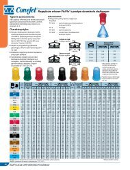
The <strong>744E</strong> Sprayer Control provides manual spray control in a compact package.<br />
The console features a lighted pressure gauge for night use and heavy-duty switches with LED indicators.<br />
• Manual spray controller in a compact package.<br />
• 3 or 5 sections control<br />
• Liquid filled 100 PSI (7 bar) pressure gauge<br />
• Lighted pressure gauge for night use<br />
• Heavy-duty switches with LED indicators<br />
• Available in a variety of kit forms using ball valve control manifolds<br />
• Kits include wiring harness<br />
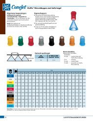
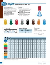
Figure 1-1: <strong>744E</strong> Sprayer Console<br />
Pressure gauge Pressure adjust switch<br />
Master switch<br />
Boom control switches<br />
98-70030 R0<br />
1
<strong>744E</strong> Sprayer Control<br />
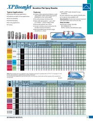
System Configurations<br />
Figure 1-2: <strong>744E</strong> Sprayer Control; 3 and 5 Sections System Diagrams<br />
3pos Mate-n-lok<br />
1<br />
2<br />
3<br />
1<br />
2<br />
3<br />
GND<br />
LTS<br />
+12V<br />
15A<br />
Reg Valve<br />
DIN<br />
BLU<br />
BRN<br />
BLK<br />
YEL/GRN<br />
BLK<br />
BLU<br />
RED<br />
3pos Mate-n-lok<br />
1<br />
2<br />
3<br />
GND<br />
LTS<br />
+12V<br />
75-50060<br />
45-05385<br />
BLK<br />
BLU<br />
RED<br />
75-50061<br />
15A<br />
45-05385<br />
Open<br />
n.c.<br />
n.c.<br />
Close<br />
1<br />
2<br />
2 www.teejet.com<br />
30<br />
20<br />
10<br />
0<br />
A<br />
B<br />
8.2 ft / 2.5m<br />
40<br />
50<br />
60 70 80 90<br />
2<br />
1<br />
0<br />
3 4 5<br />
6<br />
7<br />
bar<br />
psi<br />
100<br />
2pos WP<br />
30<br />
20<br />
10<br />
0<br />
A<br />
B<br />
8.2 ft / 2.5m<br />
+12V<br />
GND<br />
40<br />
50<br />
60 70 80 90<br />
2<br />
1<br />
0<br />
3 4 5<br />
6<br />
7<br />
bar<br />
psi<br />
100<br />
2pos WP<br />
+12V<br />
GND<br />
Boom Valve<br />
DIN<br />
+12v<br />
GND<br />
Sw<br />
RED<br />
BLK<br />
RED<br />
BLK<br />
RED<br />
BLK<br />
WHT<br />
14ga<br />
14ga<br />
14ga<br />
14ga<br />
I<br />
O<br />
I<br />
O<br />
6pos Mate-n-lok<br />
1<br />
2<br />
3<br />
4<br />
5<br />
6<br />
45-10133<br />
16.4 ft / 5.0m<br />
1<br />
2<br />
3<br />
4<br />
5<br />
6<br />
7<br />
8<br />
9<br />
45-10134<br />
16.4 ft / 5.0m<br />
BM3<br />
BM2<br />
BM1<br />
Close<br />
Open<br />
MST<br />
BM5<br />
Close<br />
BM4<br />
GND<br />
Open<br />
BM3<br />
BM1<br />
MST<br />
BM2<br />
ORN<br />
YEL<br />
GRN<br />
BRN<br />
WHT<br />
n.c.<br />
9pos Mate-n-lok<br />
PUR<br />
BRN<br />
BLU<br />
n.c.<br />
WHT<br />
ORN<br />
GRN<br />
n.c.<br />
YEL<br />
18ga<br />
18ga<br />
18ga<br />
14ga<br />
14ga<br />
1.6 ft / 0.5m<br />
18ga<br />
14ga<br />
18ga<br />
14ga<br />
18ga<br />
18ga<br />
18ga<br />
1.6 ft / 0.5m<br />
Reg Valve<br />
Boom Valve<br />
Boom Valve<br />
Boom Valve<br />
Reg Valve<br />
Boom Valve<br />
Boom Valve<br />
Boom Valve<br />
Boom Valve<br />
Boom Valve
Plumbing Diagram<br />
Figure 1-3: <strong>744E</strong> Plumbing Diagram<br />
<strong>744E</strong> Sprayer Control<br />
98-70030 R0<br />
3
<strong>744E</strong> Sprayer Control<br />
Kit Contents<br />
Unpack the installation kit and identify the required parts.<br />
Item Part Number Description Quantity<br />
1 67-20003 Male Connector, Nylon ............................................................................................1<br />
2 67-20002 Tubing Nut, Nylon ....................................................................................................3<br />
3 65-50005 Tubing Insert, Brass .................................................................................................4<br />
4 64-50023 Mounting Bracket, Nylon ..........................................................................................1<br />
5 60-10026 Lock Knob ................................................................................................................2<br />
6 60-50000 ¼″ External Tooth Lock Washer ..............................................................................2<br />
7 60-50003 1″ Bolt, Steel, Zinc Plated ........................................................................................2<br />
8 60-50001 Flat Washer, Steel, Zinc Plated ................................................................................2<br />
9 60-50009 Lock Washer, Steel, Zinc Plated ..............................................................................2<br />
10 350-0062 Hex Nut, Steel, Zinc Plated ......................................................................................2<br />
11 67-20001 Male Coupling, Nylon ...............................................................................................1<br />
12 90-50141 Accessory Bag - Items 2, 3 ,5, & 7-13 .....................................................................1<br />
13 75-50061 <strong>TeeJet</strong> <strong>744E</strong> - 5 sections console, 100 PSI .............................................................1<br />
75-50060 <strong>TeeJet</strong> <strong>744E</strong> - 3 sections console, 100 PSI .............................................................1<br />
14 98-70030 <strong>744E</strong> Manual ............................................................................................................1<br />
Item Part No. Description Illustration<br />
1 67-20003 Male Connector, Nylon<br />
2 67-20002 Tubing Nut, Nylon<br />
3 65-50005 Tubing Insert, Brass<br />
4 www.teejet.com
Item Part No. Description Illustration<br />
4 64-50023 Mounting bracket, nylon<br />
5 60-10026 Lock knob<br />
6 60-50000 ¼″ External tooth lock washer<br />
7 60-50003 1″ Bolt; steel; Zinc plated<br />
8 60-50001 Flat washer; steel; Zinc plated<br />
9 60-50009 Lock washer; steel; Zinc plated<br />
10 350-0062 Hex nut, steel; Zinc plated<br />
11 67-20001 Male coupling; Nylon<br />
12 90-50141 Accessory bag -<br />
Items 2, 3, 5, & 7-13<br />
<strong>744E</strong> Sprayer Control<br />
98-70030 R0<br />
5
<strong>744E</strong> Sprayer Control<br />
Item Part No. Description Illustration<br />
13 75-50061 <strong>TeeJet</strong> <strong>744E</strong> - 5 sections console,<br />
100 PSI<br />
75-50060 <strong>TeeJet</strong> <strong>744E</strong> - 3 sections console,<br />
100 PSI<br />
14 98-70030 <strong>744E</strong> User Manual<br />
6 www.teejet.com<br />
30<br />
20<br />
10<br />
0<br />
40<br />
50<br />
2<br />
1<br />
0<br />
3 4 5<br />
6<br />
7<br />
bar<br />
psi<br />
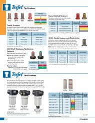
Control Housing Assembly<br />
New consoles have boom switches, gauge lamps/LEDs and boom LED soldered to the circuit board.<br />
Item Part Number Description<br />
1 60-50020 Knurled nut; Brass nickel plated<br />
2 -- Graphic panel<br />
3 64-50024 Front housing<br />
4 64-50031 Lens gauge<br />
5 51-20008 100 PSI Liquid gauge<br />
6 60-50019 Square nut (2 required)<br />
7 -- Circuit board<br />
8 32-50010 Toggle switch<br />
9 350-2610 Plastic screw<br />
10 64-50030 Foam spacer<br />
11 64-50025 Back housing<br />
12 64-50029 Elbow, nylon (Black)<br />
13 64-50032 Output cable shield; Neoprene<br />
14 64-50026 Receptacle fuse shield; Neoprene<br />
15 604-0014 Fuse, 15A<br />
60 70 80 90<br />
100
Figure 1-4: Assembly<br />
1<br />
8<br />
Illustrations shown may vary from actual product.<br />
4<br />
2<br />
6<br />
5<br />
12<br />
3<br />
10<br />
8<br />
8<br />
7<br />
6<br />
<strong>744E</strong> Sprayer Control<br />
14<br />
15<br />
13 11<br />
9<br />
98-70030 R0<br />
7
<strong>744E</strong> Sprayer Control<br />
CHAPTER 2 - INSTALLATION<br />
Mounting Bracket<br />
1. Make sure all switches on the <strong>744E</strong> Sprayer<br />
Control are turned to the “Off” position.<br />
2. Determine the best location for the <strong>744E</strong> Sprayer<br />
Control in the vehicle cab according to the following<br />
guidelines:<br />
• pressure gauge should be readily visible<br />
• switches should be within easy reach<br />
• controller bracket should rest on a flat surface<br />
• 12 volt DC power source must be accessible<br />
(maximum draw 10 amps)<br />
3. Determine the proper routing for power cables and<br />
pressure tube:<br />
• away from operators’ movement area<br />
• away from moving parts<br />
• away from sharp objects<br />
4. Install the mounting bracket using ¼″ (6.4 mm) drill,<br />
machine screws, nut, washers and lock washers<br />
as illustrated below. Attach the control housing<br />
assembly to the mounting bracket using the<br />
console adjusting knobs and washers.<br />
Figure 2-1: Mounting bracket<br />
8 www.teejet.com<br />
Pressure Gauge<br />
The tubing for the pressure gauge is supplied as part of<br />
the wiring harness. To avoid chemical leakage into the<br />
vehicle cab, the tube coupler must be installed outside<br />
of the vehicle cab. If a gauge isolator is used with the<br />
system, it should be installed in place of the coupler,<br />
also outside of the vehicle cab.<br />
The pressure gauge should be checked for accuracy<br />
each season. If the unit is equipped with a liquid-filled<br />
gauge and it does not read accurately, the gauge may<br />
need to be vented. To vent the gauge, remove the four<br />
screws in the back of the sprayer control housing and<br />
lift off the back. The rear of the gauge will be exposed.<br />
To vent the gauge, clip off the nib of the rubber plug<br />
in the back of the gauge or puncture it with a needle.<br />
Once the gauge has been vented, do not store the<br />
sprayer control on its back as this may cause a loss<br />
of fluid from within the gauge. If further inaccuracy<br />
is suspected at 0 PSI (0 bar) and a gauge isolator<br />
is being used, the isolator line may need to be bled<br />
according to the instructions furnished with the gauge<br />
isolator.
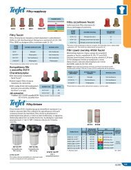
Pressure Gauge Tube Assembly<br />
1. Determine the location at which the coupler is to be<br />
installed. Cut the tubing at that point.<br />
2. Remove the tube nuts from the 3 couplers and<br />
slide the tubing through the nuts. The threaded<br />
portion of the nut should face their respective<br />
couplings. The tube should protrude approximately<br />
½″ (1 cm) beyond the nut.<br />
3. One brass tube insert is provided. This must be<br />
used with the gauge coupling assembly.<br />
4. Fluid leakage around the gauge indicates a poor<br />
connection or a defective gauge.<br />
NOTE: All cables and tubes must be placed in a way,<br />
so that they cannot be snagged or pulled with<br />
the operator’s feet. Tubes and cables must be<br />
routed around sharp metal objects, edges and<br />
moving parts with enough slack so that they<br />
will not be pulled apart when sharp turns are<br />
made.<br />
<strong>744E</strong> Sprayer Control<br />
Figure 2-2: Pressure gauge tube assembly<br />
Gauge elbow<br />
Tube insert<br />
Tube nut<br />
Tube nut<br />
Tube insert<br />
Optional isolator kit<br />
<strong>744E</strong> Sprayer control<br />
Harness<br />
Harness<br />
21 72 0-8<br />
DC: XX /XX<br />
45- 20 09 1<br />
Tube insert<br />
Tube coupling<br />
Tube insert<br />
45- 20 09 0<br />
DC:XX/XX<br />
98-70030 R0<br />
Tube nut<br />
Tube nut<br />
9
<strong>744E</strong> Sprayer Control<br />
CHAPTER 3 - MAINTENANCE<br />
Routine Procedures<br />
Several routine procedures should be followed to help<br />
maintain the <strong>744E</strong> Sprayer Control system.<br />
1. Check all wires and connections for wear, damage<br />
and frayed ends to prevent shorting out of the<br />
system.<br />
2. Make sure that the mounting bracket for the <strong>744E</strong><br />
Sprayer Control is mounted securely.<br />
3. All connections and terminals should be free of<br />
corrosion.<br />
4. The control unit is designed so that it may be<br />
removed, cleaned and stored during periods of<br />
non-use to protect it from extreme heat or cold.<br />
5. The <strong>744E</strong> Sprayer Control is NOT WATERPROOF.<br />
Do not immerse the unit when cleaning.<br />
6. Periodic flushing of the sprayer will help prevent<br />
clogging due to residue buildup.<br />
Removal of Control Unit<br />
1. De-pressurize the system.<br />
2. Uncouple the nylon pressure tube from outside<br />
the vehicle cab and allow the liquid to drain.<br />
Uncouple the tube from the bottom of the unit.<br />
3. Disconnect the input power cable from the back<br />
of the unit.<br />
4. Disconnect the output control cable from the back<br />
of the unit.<br />
5. Loosen the triangular knobs on both sides of the<br />
unit and slide the unit off of the bracket.<br />
10 www.teejet.com
1801 Business Park Drive<br />
Springfield, Illinois 62703 USA<br />
Tel: (217) 747-0235 • Fax: (217) 753-8426<br />
www.teejet.com<br />
98-70030 R0 English-US<br />
© <strong>TeeJet</strong> Technologies 2011<br />
<strong>744E</strong> Sprayer Control<br />
U S E R M A N U A L<br />
<strong>TeeJet</strong> <strong>744E</strong> Manual Sprayer Control for use with Ball Valves<br />
• Manual spray controller in a compact package.<br />
• 3 or 5 sections control<br />
• Liquid filled 100 PSI (7 bar) pressure gauge<br />
• Lighted pressure gauge for night use<br />
• Heavy-duty switches with LED indicators<br />
• Available in a variety of kit forms using ball valve control manifolds<br />
• Kits include wiring harness