MC521 Controller Installation And Operation Manual
MC521 Controller Installation And Operation Manual
MC521 Controller Installation And Operation Manual

Create successful ePaper yourself
Turn your PDF publications into a flip-book with our unique Google optimized e-Paper software.
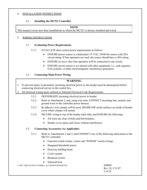
4. INSTALLATION INSTRUCTIONS<br />
4.1 Installing the <strong>MC521</strong> <strong>Controller</strong><br />
NOTE<br />
This manual covers new door installations in which the <strong>MC521</strong> is factory-installed and wired.<br />
5. WIRING INSTRUCTIONS<br />
5.1 Evaluating Power Requirements<br />
5.1.1 EVALUATE door system power requirements as follows:<br />
• ENSURE power source is a dedicated 115 VAC, 50/60 Hz source with 20A<br />
circuit rating. If four operators are used, the source should have a 30A rating.<br />
• ENSURE no more than four operators will be connected to one circuit.<br />
• ENSURE power source is not shared with other equipment, i.e., cash registers,<br />
EAS systems, or other electromagnetic interference generators.<br />
5.2 Connecting Main Power Wiring<br />
WARNING<br />
1. To prevent injury to personnel, incoming electrical power to the header must be deenergized before<br />
connecting electrical service to the control box.<br />
2. All electrical wiring must conform to National Electrical Code Requirements.<br />
5.2.1 DEENERGIZE incoming electrical power to header.<br />
5.2.2 Refer to Attachment 2, and, using wire nuts, CONNECT incoming line, neutral, and<br />
ground wires to the controller power harness.<br />
5.2.3 IF adhesive wire clamps will be used, DEGREASE metal surfaces on inside of header<br />
cover where clamps will mount.<br />
5.2.4 SECURE wiring to top of the header track tube, and ENSURE the following:<br />
• All wires are clear of belts and belt brackets.<br />
• Header cover opens and closes without interference.<br />
5.3 Connecting Accessories (As Applicable)<br />
5.3.1 Refer to Attachments 2 and 3, and CONNECT any of the following subsystems to the<br />
<strong>MC521</strong> controller:<br />
• Function switch (rotary, rocker and “POWER” switch wiring)<br />
• Stanguard threshold sensor<br />
• Doorway holding beam<br />
• Cycle counter<br />
• Breakout switch<br />
• Solenoid lock<br />
© 2007, THE STANLEY WORKS. ALL RIGHTS RESERVED. 204003<br />
Rev. D, 3/11/07<br />
3 of 23