English - Rohde & Schwarz
English - Rohde & Schwarz
English - Rohde & Schwarz

Create successful ePaper yourself
Turn your PDF publications into a flip-book with our unique Google optimized e-Paper software.
News from <strong>Rohde</strong> & <strong>Schwarz</strong><br />
Modular TETRA mobile radio system –<br />
autonomous, portable and quick to set up<br />
Universal EMI software for diverse<br />
measurement applications<br />
Complete operating and T&M product<br />
range for digital TV<br />
2004/IV<br />
184
ACCESSNET®-T Cube is a TETRA communications<br />
system for mobile applications that is<br />
modular in design and thus highly versatile. It<br />
can be operated as a standalone system, but<br />
also integrated into existing networks (page 4).<br />
The Signal Generator R&S ® SMU is continuously<br />
being enhanced. This development is<br />
reflected by the three articles in this issue<br />
that describe new features and functionalities<br />
of this high-end instrument (starting<br />
on page 16).<br />
A Handheld Spectrum Analyzer R&S ® FSH3 is<br />
currently being used on board the International<br />
Space Station (ISS) for distance-to-fault (DTF)<br />
measurements (page 28).<br />
NUMBER 184 2004/IV Volume 44<br />
Photo: NASA<br />
MOBILE RADIO<br />
2<br />
News from <strong>Rohde</strong> & <strong>Schwarz</strong> Number 184 (2004/IV)<br />
TETRA radio systems<br />
TETRA Mobile Radio System ACCESSNET®-T Cube<br />
Autonomous modular TETRA system – portable and quick to set up ..............................4<br />
Radiocommunication testers<br />
Universal Radio Communication Tester R&S ® CMU200<br />
Unprecedented speed in mobile phone production testing .............................................8<br />
Versatile application tests in (E)GPRS mobile radio .......................................................10<br />
Convenience and flexibility – the key to successful mobile radio testers .....................13<br />
Signal generators<br />
Vector Signal Generator R&S ® SMU200A<br />
Digital fading simulator with unrivalled characteristics .................................................16<br />
CDMA2000 ® and 1xEV-DV signals for demanding test scenarios ..................................19<br />
Convenient generation of 3GPP FDD HSDPA signals .....................................................22<br />
Protocol testers<br />
Protocol Tester R&S ® CRTU-W / CRTU-G<br />
More efficient generation of custom 2G/3G InterRAT test scenarios ............................25<br />
Test tip<br />
Power Meter R&S ® NRP<br />
Measuring power in mobile radio: quick results with “Recall Standard” .....................26<br />
GENERAL PURPOSE<br />
Reference<br />
Handheld Spectrum Analyzer R&S ® FSH3<br />
Put to the test on board the International Space Station ISS ........................................28<br />
44280
An automatic all-in-one solution for differential<br />
measurements directly on the wafer that can be<br />
used up to 20 GHz has been developed in cooperation<br />
with Advantest, Suss MicroTech Test<br />
Systems and <strong>Rohde</strong> & <strong>Schwarz</strong> (page 36).<br />
The new digital TV standard DVB-H enables<br />
efficient transmission of multimedia content to<br />
mobile receivers. Digital TV, however, also offers<br />
data services that appeal to a large number of<br />
users. <strong>Rohde</strong> & <strong>Schwarz</strong> supports this development<br />
with a complete product portfolio for measurement<br />
and operation (pages 46 and 50).<br />
3<br />
News from <strong>Rohde</strong> & <strong>Schwarz</strong> Number 184 (2004/IV)<br />
Spectrum analyzers<br />
Spectrum and Signal Analyzers R&S ® FSP/ FSU / FSQ<br />
High-precision measurement of absolute levels with spectrum analyzers ...................32<br />
Signal analyzers<br />
Signal Analyzer R&S ® FSQ<br />
Analysis of VSB signals with the option R&S ® FSQ-K70 .................................................34<br />
Network analyzers<br />
RF Network and Component Analyzer R3860A from Advantest<br />
Differential measurements up to 20 GHz directly on the wafer .....................................36<br />
Signal generators<br />
Microwave Signal Generators R&S ® SMR<br />
Universal sweep generators for network analysis .........................................................39<br />
EMC/FIELD STRENGTH<br />
Test systems<br />
EMI Measurement Software R&S ® EMC32-E+<br />
All-purpose software for complete EMI measurements .................................................42<br />
BROADCASTING<br />
Datacasting<br />
MPEG-2 Monitoring System R&S ® DVM<br />
TV – just pictures and sound? Not with digital TV! ........................................................46<br />
Operating and measurement equipment for the new digital TV standard DVB-H ........50<br />
MISCELLANEOUS<br />
Newsgrams ......................................................................................................................54<br />
Published by <strong>Rohde</strong> & <strong>Schwarz</strong> GmbH&Co. KG · Mühldorfstrasse 15 · 81671 München<br />
Support Center: Tel. (+49) 01805124242 · E-mail: customersupport@rohde-schwarz.com<br />
Fax (+4989) 4129-13777 · Editor and layout: Ludwig Drexl, Redaktion – Technik (German)<br />
<strong>English</strong> translation: Dept. 9UK7 · Photos: <strong>Rohde</strong> & <strong>Schwarz</strong> · Printed in Germany · Circulation (German,<br />
<strong>English</strong>, French, Russian and Chinese) 90000 approx. 4 times a year · ISSN 0028-9108 · Supply free of<br />
charge through your nearest <strong>Rohde</strong> & <strong>Schwarz</strong> representative · Reproduction of extracts permitted if source<br />
is stated and copy sent to <strong>Rohde</strong> & <strong>Schwarz</strong> München.<br />
R&S ® is a registered trademark of <strong>Rohde</strong> & <strong>Schwarz</strong> GmbH&Co. KG. Trade names are trademarks of the owners. CDMA2000 ® is a registered<br />
trademark of Telecommunications Industry Association (TIA USA). The Bluetooth word mark and logos are owned by the Bluetooth SIG, Inc.<br />
and any use of such marks by <strong>Rohde</strong> & <strong>Schwarz</strong> is under license.
MOBILE RADIO<br />
ACCESSNET ®-T Cube is a TETRA<br />
communications system for mobile<br />
applications that is modular in design<br />
and thus highly versatile. It can be<br />
operated as a standalone system, but<br />
also integrated into existing networks.<br />
Initial orders were received soon after<br />
market launch, and these systems are<br />
now already in use. User feedback has<br />
been very positive.<br />
* IP: International Protection; labeling of housing<br />
using the internationally accepted IP abbreviation.<br />
TETRA radio systems<br />
4<br />
News from <strong>Rohde</strong> & <strong>Schwarz</strong> Number 184 (2004/IV)<br />
TETRA Mobile Radio System ACCESSNET®-T Cube<br />
Autonomous modular TETRA system<br />
– portable and quick to set up<br />
Developed to customer<br />
specifications<br />
Before developing ACCESSNET ®-T Cube,<br />
<strong>Rohde</strong> & <strong>Schwarz</strong> carried out intensive<br />
market research and interviewed potential<br />
users from government authorities<br />
and organizations with public safety<br />
tasks, the military and emergency relief<br />
services as well as private network operators.<br />
<strong>Rohde</strong> & <strong>Schwarz</strong> specifically<br />
asked them about their requirements for<br />
a mobile TETRA communications system.<br />
The responses indicated the following<br />
main requirements:<br />
◆ Easy to transport so that the system<br />
can be quickly taken to the site by<br />
vehicle or helicopter<br />
◆ Quick and easy to set up on-site<br />
◆ Ready to operate within a few<br />
minutes<br />
◆ Designed with configuration or<br />
operating parameters that can be<br />
easily modified on-site, a must in<br />
practical use<br />
These and numerous other requirements<br />
were implemented when the TETRA<br />
ACCESSNET ®-T Cube communications<br />
system was developed. The Cube was<br />
planned and designed as a commercial<br />
off-the-shelf (COTS) system made from<br />
standard components.<br />
Completely modular system<br />
components<br />
The ACCESSNET ®-T Cube is completely<br />
modular in design; all modules have<br />
standardized dimensions and none<br />
weighs more than 50 kg (FIGs 1 and 2).<br />
Due to these specifications, the logistics<br />
aspects involved in transportation and<br />
use of this system are easier to plan and<br />
to handle. Although the ACCESSNET ®-T<br />
Cube is primarily designed for mobile<br />
use, it can, of course, also be operated<br />
as a fixed installation in a vehicle or temporary<br />
building.<br />
All modules are installed in standard<br />
aluminum housing units with shockmounted<br />
frames that ensure the safe<br />
transport and operation of the built-in<br />
COTS equipment even under adverse<br />
transport and environmental conditions.<br />
The modules were developed on<br />
the basis of current industrial standards.<br />
When necessary, MIL standards have<br />
also been taken into account. All connectors,<br />
including the RF connectors,<br />
are designed as instant plug-in connectors<br />
according to the IP 65 * protection<br />
class. You thus receive a robust and reliable<br />
system while saving on the costs<br />
that a system developed completely in<br />
line with the MIL standard would incur.<br />
This method is gaining worldwide acceptance<br />
in the development of technical<br />
systems, including in the military.<br />
Since different types of missions call<br />
for different system colors (systems for<br />
peacekeeping missions must be graybeige,<br />
for example), the modules are<br />
available in three colors: gray-beige,<br />
olive-green and blue.<br />
The ACCESSNET ®-T Cube is based on<br />
the same components as the “large”<br />
ACCESSNET ®-T [*]. The standardized<br />
basic hardware and software of<br />
the TETRA system technology from<br />
<strong>Rohde</strong> & <strong>Schwarz</strong> help keep costs low,<br />
plus they ensure a true synergetic effect<br />
in further development.
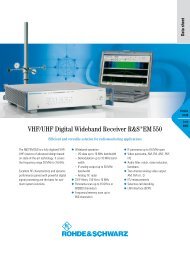
FIG 1 The TETRA ACCESSNET ®-T Cube radio system is ready for operation in only a few minutes.<br />
Base station module<br />
The core of the ACCESSNET ®-T Cube is<br />
the base station module (BSM) with the<br />
TETRA outdoor base station (TOB). If a<br />
48 V DC voltage source and a transmitting<br />
and receiving antenna are available,<br />
the BSM can be used as a single-cell<br />
system. Setting up the BSM and putting<br />
it into operation takes no more than<br />
approximately ten minutes. After it is<br />
connected to the power supply and the<br />
antennas, the system is ready for operation.<br />
The BSM includes the following<br />
components:<br />
5<br />
News from <strong>Rohde</strong> & <strong>Schwarz</strong> Number 184 (2004/IV)<br />
◆ Local exchange<br />
◆ Network management server<br />
◆ Transmit and receive unit<br />
◆ E1 and LAN interfaces for external<br />
connection<br />
◆ Heating and cooling elements<br />
If a high volume of communications is<br />
involved, the BSM can also be supplied<br />
with two TETRA RF carriers; the second<br />
carrier can also be used for (1+1) redundancy.<br />
The ACCESSNET ®-T Cube can<br />
be deployed as a standalone system<br />
but also connected to ACCESSNET ®-T<br />
exchanges, expanding existing networks.<br />
The network management server (NMS)<br />
functions as a client/server. The server<br />
is located in the BSM and can be connected<br />
to a client via a protected LAN<br />
connection. Commercially available laptops<br />
with a LAN interface meet the<br />
system requirements for client controllers.<br />
A specially protected laptop is available<br />
so that the ACCESSNET ®-T Cube<br />
can be used under adverse environmental<br />
conditions (FIG 3).<br />
The NMS is of special importance for the<br />
flexibility of the ACCESSNET ®-T Cube.<br />
For example, if the frequency that is set
MOBILE RADIO TETRA radio systems<br />
Protests<br />
Transports of material from the fuel reprocessing plant at La<br />
Hague in France to Germany are a regular target for protestors.<br />
The forces in the field are responsible for accompanying<br />
the transports and ensuring the security of protestors and<br />
passers-by. For roughly three years, the authorities responsible<br />
for transports have been using an ACCESSNET ®-T TETRA<br />
radio system from <strong>Rohde</strong> & <strong>Schwarz</strong>, which ensures confidential<br />
and secure communications. The installed network covers<br />
a defined area and has a predefined capacity. However, even<br />
the best theoretical plans can go awry. Unanticipated gaps in<br />
coverage may occur at any time – for example, if it is not possible<br />
to stick to scheduled routes.<br />
This type of problem can be easily solved with the<br />
ACCESSNET ®-T Cube. The Cube can be quickly transported to<br />
the new site and put into operation, and it is just as quickly<br />
integrated into the stationary TETRA system. To do this, an<br />
S 0 line (128 kbit/s) is connected to the ISM, which instantly<br />
makes it possible for users to place calls to and from the radio<br />
cell of the Cube system. For the security forces, it is especially<br />
crucial that their control center be included in communications.<br />
With these measures, a cell is added to the existing<br />
TETRA network without compromising its features.<br />
Large events<br />
During large events, the security of thousands of visitors<br />
needs to be ensured. This is no easy task for the event organizers<br />
and especially not for police squads, rescue services,<br />
emergency relief services, fire brigades, etc, that are involved.<br />
If these events are held in remote parts of the country – such<br />
as is done with rallye competitions in order to minimize the<br />
level of noise that non-participants are exposed to – gaps<br />
in coverage or insufficient network capacity are not uncommon.<br />
Setting up a stationary network solely for such events is<br />
usually just too costly. In such a scenario, the ACCESSNET ®-T<br />
Cube is ideal for companies that specialize in lending communications<br />
systems.<br />
The basic model is a good solution at such events. It features<br />
a power supply module (PSM), a base station module<br />
(BSM) for two TETRA RF carriers and a branching equipment<br />
module (BEM) for operation with a transmitting and receiving<br />
antenna. If a connection to the control center or the telephone<br />
network is necessary, an ISM is simply added to the<br />
Examples of ACCESSNET ® -T Cube applications<br />
6<br />
News from <strong>Rohde</strong> & <strong>Schwarz</strong> Number 184 (2004/IV)<br />
communications system. If there is a connection to the telephone<br />
network, calls can also be made from TETRA terminals<br />
to GSM networks, for example.<br />
Before an event starts, the terminals are distributed to the<br />
various organizations involved; if problems occur, coordination<br />
and mission directives can be handled via the control<br />
center. TETRA functions such as dynamic group number<br />
assignment (DGNA), where groups are created by the control<br />
center according to the task at hand and where the terminals<br />
are assigned via the TETRA system, are, of course, supported.<br />
DGNA eliminates the loss of valuable time for coordination<br />
activities. Assignment is handled in the background without<br />
involving the group participants. The existing groups remain<br />
intact, and they are integrated into the communications only<br />
in the case of a group call to the new group. Confidentiality is<br />
ensured at all times; if necessary, the various groups can communicate<br />
with each other.<br />
Out-of-area missions<br />
This term refers to missions at locations where radiocommunications<br />
is not possible either because there is no infrastructure<br />
or the existing infrastructure is no longer available, e.g.<br />
after catastrophic floods or earthquakes as well as during military<br />
peacekeeping missions.<br />
In such situations, it must be possible to set up a radiocommunications<br />
infrastructure and put it into operation within a<br />
minimum amount of time. But it must also be possible to connect<br />
various external systems – to the extent available. These<br />
are all challenges where the ACCESSNET®-T Cube excels. It<br />
takes only a few minutes to set up a radio network and put<br />
it into operation. External systems with transitions to other<br />
radio or telephone networks can quickly be integrated using<br />
the ISM. If broad areas need to be covered by radio, several<br />
BSMs can be connected to the exchange via microwave links<br />
or, if possible, via E1 lines. Thus, a multicell mobile TETRA<br />
system for communications among the forces in the field is<br />
available in no time at all.
at the site is already occupied by other<br />
systems, this might prevent operation<br />
of the Cube system. However, you can<br />
modify the on-site configuration within<br />
a few minutes by using the client for the<br />
configuration and error management in<br />
the NMS. For example, you can enter<br />
the transmit and receive frequencies in<br />
the client, which are then transferred<br />
to the Cube system. After a restart, the<br />
BSM operates at the new frequencies.<br />
The terminals do not have to be set since<br />
they scan the frequency range for a<br />
system channel, provided that they have<br />
been programmed to do so.<br />
Voltage supply<br />
With varying sites, the available voltage<br />
supply is often not known. In these<br />
cases, the power supply module (PSM)<br />
is used to supply power to the modules.<br />
It can process input voltages of<br />
either 24 V or 48 V DC as well as 90 V to<br />
264 V AC. A plug-in for 12 V DC is also<br />
available as an option. A battery pack<br />
module (BPM) can be provided if there is<br />
no primary voltage supply available or to<br />
ensure uninterrupted operation.<br />
Antenna coupling<br />
7<br />
News from <strong>Rohde</strong> & <strong>Schwarz</strong> Number 184 (2004/IV)<br />
Using more than one TETRA RF carrier<br />
would require up to six antennas. However,<br />
the branching equipment module<br />
(BEM) makes this unnecessary. It contains<br />
an antenna coupling network that<br />
supports two antennas installed at least<br />
six meters apart, ideally on two antenna<br />
masts.<br />
Exchange<br />
Special requirements also demand special<br />
solutions, such as when you need<br />
to set up a complete mobile system<br />
with multiple cells or provide transitions<br />
to other communications networks.<br />
In this case, the answer is the interconnection<br />
& switching module (ISM),<br />
which makes it possible to implement<br />
a transportable multicell TETRA network<br />
for mobile use. In addition to featuring<br />
a powerful exchange, it also provides<br />
interfaces and gateways. Various<br />
interface cards allow analog or digital<br />
systems or networks to be connected;<br />
they provide S 0 or S 2 M/E1 interfaces,<br />
for example. An A-CAPI soft-<br />
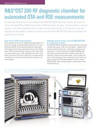
FIG 2 Each ACCESSNET ®-T Cube module weighs less than 50 kg. Left: base station; top right: power supply;<br />
bottom right: antenna coupler.<br />
FIG 3 Laptop for outdoor use.<br />
ware interface that permits customerspecific<br />
applications to be connected<br />
to the Cube system is implemented by<br />
using a gateway controller in the ISM.<br />
The A-CAPI interface is also available in<br />
ACCESSNET ®-T radio systems, making it<br />
possible to use the same applications in<br />
the Cube system.<br />
Harald Haage<br />
More information and data sheet at<br />
www.rohde-schwarz.com<br />
(search term: Cube)<br />
REFERENCES<br />
[*] ACCESSNET®-T – the digital mobile radio<br />
system from <strong>Rohde</strong> & <strong>Schwarz</strong>. News<br />
from <strong>Rohde</strong> & <strong>Schwarz</strong> (2003) No. 178,<br />
pp 6–13
MOBILE RADIO Radiocommunication testers<br />
During production, the transmit<br />
and receive levels (RSSI = receiver<br />
signal strength indicator) of GSM<br />
phones are aligned throughout the<br />
entire frequency range. Previous<br />
alignment procedures took several<br />
tens of seconds – depending on<br />
the number of frequency/level<br />
combinations to be measured. The<br />
R&S ® CMU-K47 software option<br />
(Smart Alignment@GSM-MS) makes<br />
intelligent use of the GSM frame/slot<br />
structure and performs alignment in<br />
just 0.25 seconds – at a maximum of<br />
50 frequencies and seven levels per<br />
More information and data sheet at<br />
www.rohde-schwarz.com<br />
(search term: CMU200)<br />
frequency.<br />
8<br />
News from <strong>Rohde</strong> & <strong>Schwarz</strong> Number 184 (2004/IV)<br />
Universal Radio Communication Tester R&S ® CMU200<br />
Unprecedented speed in mobile<br />
phone production testing<br />
Previous alignment strategies<br />
were relatively slow<br />
Conventional procedures for TX calibration<br />
set each frequency/level combination<br />
separately on the phone, and the<br />
tester measures the actual transmit level<br />
at each frequency. In the case of RX calibration,<br />
each frequency/level combination<br />
is separately set on the tester, and<br />
the phone logs the levels received. The<br />
results obtained by the tester and by the<br />
phone yield correction values that are<br />
stored in the phone.<br />
The power versus slot measurement of<br />
the R&S ® CMU200 speeds up calibration.<br />
It accelerates TX calibration by a factor<br />
of 8 (= number of timeslots per frame).<br />
The phone must be able, however, to<br />
transmit at different levels in each of the<br />
eight timeslots of a frame.<br />
Smart Alignment ensures high<br />
speed<br />
The new Smart Alignment@GSM-MS<br />
option makes calibration very fast. Now<br />
that state-of-the-art GSM phones have<br />
multislot capability, this feature can be<br />
used to significantly speed up calibration<br />
owing to the fact that the mobile<br />
phones are able to perform the following:<br />
◆ Output a different level in every<br />
timeslot of a frame<br />
◆ Evaluate the level of every timeslot of<br />
a frame<br />
◆ Identify the channel structure of every<br />
timeslot of a frame<br />
This means that basically every timeslot<br />
of a frame can be used for a calibration<br />
step.<br />
The frequency is set in line with the<br />
frame grid. Since the settling time of the<br />
synthesizer corrupts the measurement<br />
result, one timeslot (577 µs) per frame<br />
is used for settling instead of calibration.<br />
Smart Alignment uses timeslot 7 for settling;<br />
timeslots 0 to 6 are available for<br />
calibration.<br />
RX calibration<br />
FIGs 1 and 2 show the typical transmit<br />
signal characteristic of the<br />
R&S ® CMU200 and the related configuration.<br />
A frequency correction channel<br />
(FCH) is transmitted in the first timeslot<br />
of the first frame; the phone detects the<br />
FCH and uses it for frequency synchronization.<br />
The remaining timeslots are<br />
filled with dummy bursts. A positive side<br />
effect is that the synchronized frequency<br />
can also be used for calibrating the VCO<br />
in the phone.<br />
Synchronization channels (SCHs) with<br />
user-configurable levels are transmitted<br />
in the other frames. SCHs have a longer<br />
training sequence and thus make time<br />
synchronization easier for the phone.<br />
The phone itself is the measuring instrument<br />
as it provides the results that are<br />
required in order to determine the correction<br />
values for the receive level.<br />
The number of selected frequencies<br />
determines the cycle time of the transmit<br />
sequence. The maximum cycle time<br />
is 230 ms (= 50 frame periods).<br />
TX calibration<br />
FIGs 3 and 4 show the typical transmit<br />
signal characteristic of the phone<br />
and the TX calibration configuration.<br />
After the start of the measurement, the<br />
first timeslot of the first frame triggers<br />
the measurement sequence, which
Generator level<br />
FCH burst<br />
then runs automatically until it is completed.<br />
It is subsequently possible to<br />
fetch all results and determine the correction<br />
values for the transmit levels<br />
of the phone. Here, too, the number<br />
of selected frequencies determines<br />
the measurement time, which is again<br />
max. 230 ms.<br />
Combined TX/RX calibration<br />
In the case of GSM, the uplink and<br />
downlink frequency ranges are separated<br />
by duplex spacing and are, there-<br />
Channel 1 Channel 2 Channel 3 Channel 4 Channel 5<br />
Dummy<br />
bursts<br />
Hop to next frequency<br />
1 frame = 4.6 ms<br />
Hop to next frequency<br />
Hop to next frequency<br />
Hop to next frequency<br />
SCH bursts SCH bursts SCH bursts SCH bursts<br />
Time<br />
. . .<br />
Hop to next frequency<br />
9<br />
News from <strong>Rohde</strong> & <strong>Schwarz</strong> Number 184 (2004/IV)<br />
fore, not allowed to overlap. This means<br />
that receiver and transmitter can be calibrated<br />
simultaneously. This reduces the<br />
process time by half so that a phone can<br />
be calibrated in just 0.25 s.<br />
Summary<br />
FIG 1 RX calibration: typical time characteristic of the R&S ® CMU200 transmit signal.<br />
FIG 2 RX calibration: configuration of the R&S ® CMU200 transmit sequence.<br />
The R&S ® CMU-K47 option enables the<br />
Universal Radio Communication Tester<br />
R&S ® CMU200 to benefit from the<br />
advantages of the GSM standard and of<br />
Phone transmit level<br />
modern GSM phones. With this option,<br />
the alignment of a GSM mobile phone in<br />
production – which is a significant part<br />
of total test time – can be performed at<br />
unprecedented speed.<br />
Dieter Tiroch<br />
Channel 1 Channel 2 Channel 3 Channel 4 Channel 5<br />
Hop to next frequency<br />
Hop to next frequency<br />
Bursts 1 to 7 Bursts 1 to 7 Bursts 1 to 7 Bursts 1 to 7 Bursts 1 to 7<br />
1 frame = 4.6 ms<br />
FIG 3 TX calibration: typical time characteristic of the mobile phone transmit signal.<br />
FIG 4 TX calibration: configuration of the R&S ® CMU200 receive sequence.<br />
Hop to next frequency<br />
Hop to next frequency<br />
Time<br />
. . .<br />
Hop to next frequency
43238/16<br />
MOBILE RADIO Radiocommunication testers<br />
A new software option for the<br />
R&S ® CMU200 allows you to test<br />
applications for 2.5G mobile phones.<br />
For example, you can now test the<br />
transmission or reception of multi-<br />
media message services (MMS),<br />
Internet browsing or video streaming<br />
within a simulated (E)GPRS network<br />
environment. In addition to measuring<br />
the known RF parameters of power,<br />
spectrum or modulation, you can now<br />
also perform such tasks as displaying<br />
data throughput or analyzing<br />
protocols.<br />
10<br />
News from <strong>Rohde</strong> & <strong>Schwarz</strong> Number 184 (2004/IV)<br />
Universal Radio Communication Tester R&S ® CMU200<br />
Versatile application tests in<br />
(E)GPRS mobile radio<br />
New value-added services …<br />
At the beginning of the mobile radio<br />
era, users were satisfied if they could<br />
simply make phone calls from virtually<br />
anywhere. Today, they enjoy a much<br />
wider range of communications services.<br />
By using state-of-the-art mobile<br />
phones fitted with a large color display<br />
and an integrated digital camera, they<br />
exchange photos and video sequences,<br />
browse the Internet or load videos. The<br />
push-to-talk voice service is becoming<br />
increasingly popular; based on the voice<br />
over IP data service, it provides a group<br />
of people with inexpensive voice communications<br />
in walkie-talkie mode.<br />
Modern generations of mobile radio provide<br />
the necessary technical prerequisites<br />
for all these services. Yet they also<br />
present new challenges to manufacturers<br />
of T&M equipment. While it used to<br />
be sufficient to test the characteristics<br />
of the transmitter or receiver of a mobile<br />
phone, additional tests are now required<br />
to ensure smooth operation of the highly<br />
diverse applications. The R&S ® CMU200<br />
has proven to be outstanding for this<br />
purpose. Due to its flexible platform<br />
concept, it effortlessly keeps pace with<br />
changes in mobile radio and ideally<br />
meets new requirements in application<br />
tests.<br />
… require a number of tests<br />
The tests required for available applications<br />
are just as varied as the applications<br />
themselves. The currently available<br />
applications can be differentiated<br />
by any number of factors, e.g. realtime<br />
requirements, error control, or point-topoint,<br />
point-to-multipoint or broadcast<br />
communications. The Internet protocol<br />
(IP) – which ensures data exchange<br />
across network boundaries – provides<br />
a common basis and means of accessing<br />
most applications. Together with<br />
the Internet, it has conquered the world<br />
and evolved into the international standard<br />
in data communications. Also in<br />
radiocommunications, these applications<br />
are usually implemented according<br />
to the client-server principle, where,<br />
for example, an Internet server provides<br />
the desired application on the<br />
mobile phones of a number of clients on<br />
demand.<br />
To use several IP-based applications in<br />
mobile radio, additional signaling routines<br />
are required. For example, when<br />
transmitting an MMS via a GPRS or<br />
EGPRS(EDGE) mobile phone, the MMS<br />
center informs the receiver via the short<br />
message service (SMS) that a message<br />
has been sent and asks the receiver to<br />
retrieve it.<br />
The range of possible application tests<br />
includes simple Go/NoGo tests, performance<br />
analyses, evaluations of the<br />
interaction between different applications<br />
running simultaneously on a<br />
mobile phone through to the testing<br />
of the interoperability between two<br />
mobile phones. To test applications on a<br />
mobile phone, the R&S ® CMU200 simulates<br />
a radio network; external computers<br />
connected to the radio tester provide<br />
the required servers (FIG 1). Yet<br />
another challenge is the detailed examination<br />
of protocol and signaling procedures<br />
(enablers) that are often necessary<br />
at the start and which usually<br />
require the use of protocol testers<br />
such as the R&S ® CRTU-G [1]. Since the<br />
R&S ® CMU200 and the R&S ® CRTU-G
share a common platform, the data that<br />
is obtained can be exchanged between<br />
them and analyzed further.<br />
(E)GPRS application tests with<br />
the R&S ® CMU200<br />
Owing to significant protocol stack<br />
extensions, the R&S ® CMU200 now<br />
also allows you to test applications<br />
via GPRS and EGPRS(EDGE) mobile<br />
phones simply by activating a new software<br />
option. In addition to the application<br />
test for CDMA2000 ® [2], this is yet<br />
another standard ideally supported by<br />
the R&S ® CMU200, proving its flexible,<br />
future-proof concept. The new software<br />
option makes it possible to test almost<br />
any IP-based applications in packet-oriented<br />
mode via an IP gateway. You can<br />
simply test proper functioning, but also<br />
check whether different applications<br />
that are simultaneously activated on a<br />
mobile phone run smoothly. GPRS and<br />
EGPRS, the offshoots of the GSM standard,<br />
achieve data transmission rates<br />
of up to 171.2 kbit/s and 473.6 kbit/s<br />
respectively, thus allowing a multitude<br />
of applications to be carried out, some of<br />
them even with realtime requirements.<br />
In addition to displaying the current data<br />
throughput of the IP packets exchanged<br />
between mobile phone and server<br />
(FIG 2), the R&S ® CMU200 also records<br />
various transmission protocols (FIG 3).<br />
Design engineers are thus able to thoroughly<br />
analyze not only the IP protocol,<br />
but also a number of other radio-specific<br />
protocols such as radio link control<br />
(RLC) or medium access control (MAC).<br />
Regardless of these activities, it is still<br />
possible to measure and analyze the RF<br />
signals transmitted by GPRS or EGPRS<br />
mobile phones on the R&S ® CMU200<br />
with respect to power, spectrum or modulation<br />
(FIG 4). Unlike the previous transmitter<br />
test, the measurement is now performed<br />
as part of the application data<br />
transmission and no longer on the basis<br />
of pseudo-random binary sequences<br />
11<br />
News from <strong>Rohde</strong> & <strong>Schwarz</strong> Number 184 (2004/IV)<br />
FIG 1<br />
Simulation of a radio network by means of the<br />
R&S ® CMU200. PCs connected via Ethernet to<br />
the radio tester provide one or more servers.<br />
FIG 2<br />
Throughput of the<br />
IP data packets<br />
exchanged between<br />
mobile phone and<br />
server.<br />
��������<br />
FIG 3 The R&S ® CMU200 also records different transmission protocols.<br />
��<br />
����������
MOBILE RADIO Radiocommunication testers<br />
FIG 4 During the application test, the R&S ® CMU200 can also measure the RF signals transmitted by GPRS or<br />
EGPRS mobile phones with regard to power, spectrum or modulation. This figure shows an example of the ‘due to<br />
modulation’ spectrum measurement of a mobile phone transmitter.<br />
FIG 5 Test setup for data end-to-end tests, for example for testing the exchange of an MMS message between<br />
two mobile phones.<br />
12<br />
News from <strong>Rohde</strong> & <strong>Schwarz</strong> Number 184 (2004/IV)<br />
(PRBS). If two R&S ® CMU200 testers are<br />
available, the application tests can be<br />
expanded to accommodate data end-toend<br />
tests, for example for checking the<br />
exchange of an MMS message between<br />
two mobile phones (FIG 5). If only one<br />
R&S ® CMU200 is available, the transmission<br />
and slightly delayed reception of an<br />
MMS message with one mobile phone<br />
can also be implemented using the loopback<br />
setting in the MMSC.<br />
Powerful aid in the<br />
development lab<br />
The new software option R&S ® CMU-K92<br />
for the R&S ® CMU200 for the first time<br />
allows application design engineers<br />
to test their work in the lab on mobile<br />
phones in a simulated radio network.<br />
In this case, the main focus is on proving<br />
that the application runs smoothly<br />
on the mobile phone under normal operating<br />
and radio conditions. For these<br />
applications, which can be divided<br />
into mobile-originated and mobile-terminated<br />
applications, this represents<br />
the first realistic test after completion<br />
of the simulation tests on the development<br />
computer. When testing mobileoriginated<br />
applications, data communication<br />
is initiated on the mobile phone,<br />
for example by calling up an integrated<br />
browser with subsequent access to the<br />
data of a web server connected via the<br />
Ethernet interface of the R&S ® CMU200.<br />
An example of a test of a mobile-terminated<br />
application is an SMS transmission,<br />
either from a computer connected<br />
to the tester or directly from the tester to<br />
the mobile phone.
Using this new option, mobile phone<br />
designers are now able to analyze the RF<br />
parameters of the mobile phone transmitter<br />
while the applications are running.<br />
Power consumption, feasible data rates<br />
at different signal levels or, for example,<br />
the behavior under fading conditions<br />
can thus be thoroughly examined.<br />
In addition, network operators that perform<br />
these application tests to check<br />
new mobile phones before approving<br />
them for their networks can use<br />
this option to ensure smooth network<br />
operation.<br />
Modern mobile radio systems sparkle<br />
with continuously new innovations,<br />
placing ever more complex develop-<br />
ment and production demands on<br />
mobile phone manufacturers. To meet<br />
such challenging tasks, you need<br />
a mobile radio tester that can keep<br />
pace with the rapid rate of innovation<br />
without compromising on operating<br />
convenience.<br />
Future prospects<br />
13<br />
News from <strong>Rohde</strong> & <strong>Schwarz</strong> Number 184 (2004/IV)<br />
Application tests are becoming more<br />
and more important in mobile radio.<br />
<strong>Rohde</strong> & <strong>Schwarz</strong> is meeting this trend<br />
by continuously developing new solutions<br />
in this field. The licensing authorities<br />
have responded to changes in the<br />
way mobile communications are used:<br />
By developing test scenarios with exact<br />
specifications, they are defining appropriate<br />
tests at the application level that<br />
will ensure that mobile radio networks<br />
will also operate smoothly in the future.<br />
Thomas A. Kneidel<br />
Universal Radio Communication Tester R&S ® CMU200<br />
Convenience and flexibility – the key<br />
to successful mobile radio testers<br />
Automatic timeslot<br />
configuration<br />
The expansion of the GSM standard to<br />
packet data services (GPRS and EGPRS)<br />
considerably increased the complexity of<br />
mobile radio systems. To meet this challenge,<br />
a tester must cover all relevant<br />
scenarios. Especially when you use testers<br />
in development, you must be able to<br />
set a large number of parameters to your<br />
specific requirements. However, this<br />
may present very difficult problems, for<br />
example if you want to determine which<br />
of the numerous parameters must be<br />
set and how to set them in order for the<br />
tester to generate the expected scenario.<br />
Therefore a state-of-the-art mobile radio<br />
tester must take a new approach in<br />
More information and data sheet at<br />
www.rohde-schwarz.com<br />
(search term: CMU200)<br />
REFERENCES<br />
[1] Protocol Tester R&S ® CRTU-G: Reducing<br />
test time through automation. News from<br />
<strong>Rohde</strong> & <strong>Schwarz</strong> (2004) No. 182,<br />
pp 16–17<br />
[2] Universal Radio Communication Tester<br />
R&S ® CMU200: Testing CDMA2000 ®<br />
data applications. News from<br />
<strong>Rohde</strong> & <strong>Schwarz</strong> (2004) No. 182,<br />
pp 11–13<br />
operation. The Universal Radio Communication<br />
Tester R&S ® CMU200 previously<br />
came with a configurator for the GSM<br />
system that automatically selected the<br />
optimum timeslot configuration in accordance<br />
with the mobile phone’s capabilities<br />
and the desired type of connection<br />
[*]. This timeslot configurator has<br />
now been expanded by an automatic<br />
measurement configurator and a wizard.
Automatic measurement<br />
configuration<br />
After you activate the configurator and<br />
the connection is set up, the tester automatically<br />
sets the measurements to the<br />
optimum timeslot configuration of the<br />
current connection and switches to the<br />
menu that is most probably needed. In<br />
most cases, you will not need to modify<br />
the configuration. With the multislot<br />
power ramp measurement, for example,<br />
the number of timeslots to be displayed<br />
and the measurement timeslot are set in<br />
such a way that as many active timeslots<br />
as possible can be displayed at maximum<br />
resolution on the screen (FIG 1).<br />
Convenient wizard<br />
MOBILE RADIO Radiocommunication testers<br />
Using the wizard, you can configure<br />
the entire tester for the measurement<br />
task at hand in a single step. To set the<br />
R&S ® CMU200 for 8PSK EGPRS measurements,<br />
for example, select the EGPRS<br />
8PSK presetting in the wizard (FIG 2).<br />
This activates the automatic timeslot<br />
FIG 1 Fitted with the measurement configurator, the R&S ® CMU200 automatically sets both the optimum multislot power ramp measurement and the spectrum measurements, depending<br />
on the type of connection and active timeslot combination. The example on the left shows the selected power ramp measurement settings for a connection with two active uplink<br />
timeslots; on the right are the selected settings for a connection with four active uplink timeslots.<br />
14<br />
News from <strong>Rohde</strong> & <strong>Schwarz</strong> Number 184 (2004/IV)<br />
configurator and the automatic measurement<br />
configurator as well as any<br />
second transmitter that is available<br />
(option R&S ® CMU-B95) for the BCCH. In<br />
addition, the network support parameter<br />
is set to GSM + EGPRS, the service<br />
selection to packet data and the coding<br />
scheme to MCS9.<br />
Limit weighting<br />
The R&S ® CMU200 also makes it easy<br />
to set the off power limit in the case of<br />
multislot connections. In practice, there<br />
are two interpretations for this measurement.<br />
One of them references the off<br />
power limit for all timeslots to the timeslot<br />
with the maximum power, i.e. the<br />
permissible residual transmit power of a<br />
mobile phone on non-active timeslots is<br />
the same across all timeslots (FIG 3, left).<br />
The second interpretation references the<br />
off power limit to the specific power of<br />
the individual timeslots, i.e. the permissible<br />
residual transmit power of a mobile<br />
phone changes with each timeslot (FIG 3,<br />
right). Weighting the permissible residual<br />
transmit power in a non-active timeslot<br />
is difficult if the timeslot is surrounded<br />
by two active timeslots with different<br />
power because, in the non-active timeslot,<br />
the off power limit of the preceding<br />
active timeslot must be replaced by the<br />
off power limit of the succeeding active<br />
timeslot at some point. Whichever interpretation<br />
you prefer, the R&S ® CMU200<br />
handles both; you can change between<br />
the two using a selection switch.<br />
BER search routine<br />
Determining the absolute RF level for<br />
a defined bit error ratio is very timeconsuming<br />
and almost impossible<br />
to do manually. In this case, too, the<br />
R&S ® CMU200 supports you with its<br />
user-friendly search routine. Depending<br />
on the offset from the desired bit<br />
error ratio, the search routine automatically<br />
modifies the averaging depth of the<br />
measurement and the step size of the RF<br />
level change, thus very quickly determining<br />
the absolute RF level for a defined<br />
bit error ratio.
New GSM functionality<br />
Apart from convenient operation, you<br />
also expect a tester to cover all necessary<br />
functionalities of a mobile radio<br />
standard. Here, too, the R&S ® CMU200<br />
is always up to date. For example, if the<br />
latest software has been loaded and<br />
the option R&S ® CMU-B95 installed,<br />
the R&S ® CMU200 is able to provide<br />
a PBCCH for (E)GPRS packet data<br />
transmissions – in addition to numerous<br />
other functionalities. Switchover<br />
between two- and three-digit MNC in<br />
all GSM networks is also available. With<br />
the new option R&S ® CMU-K26, the<br />
R&S ® CMU200 even supports GT800, the<br />
Chinese version of the R-GSM standard.<br />
Summary<br />
The Universal Radio Communication<br />
Tester R&S ® CMU200 combines flexibility,<br />
operating convenience, measure-<br />
FIG 2<br />
Using the wizard,<br />
you can optimally<br />
set the<br />
R&S ® CMU200 for<br />
a specific measurement<br />
task in<br />
a single operating<br />
step. All you need<br />
to do is select the<br />
desired task from a<br />
list; everything else<br />
is done automatically<br />
by the tester.<br />
FIG 3 The R&S ® CMU200 can reference the off power limit both to the timeslot with the maximum power (left) and to the individual timeslots (right). The wide dynamic range that may<br />
be required when referencing the off power limit to the individual timeslots does not pose any problems for the tester.<br />
15<br />
News from <strong>Rohde</strong> & <strong>Schwarz</strong> Number 184 (2004/IV)<br />
ment speed, functionality and precision<br />
in a single instrument. Such versatility<br />
makes the R&S ® CMU200 successful in<br />
all areas of mobile radio testing.<br />
Rudolf Schindlmeier<br />
More information and data sheet at<br />
www.rohde-schwarz.com<br />
(search term: CMU200)<br />
REFERENCES<br />
[*] R&S ® CMU200 – Solutions not only<br />
for (E)GPRS mobile radio development.<br />
News from <strong>Rohde</strong> & <strong>Schwarz</strong> (2004)<br />
No. 181, pp 14–15
MOBILE RADIO Signal generators<br />
Impairments and various problems<br />
such as Doppler shifts and construc-<br />
tive or destructive superposition of<br />
multipath propagation with different<br />
signal delays may occur during the<br />
radio transmission of signals. The<br />
mobile radio standards stipulate<br />
appropriate measurements with<br />
defined channel models to ensure<br />
that radio systems are not impaired by<br />
such channel characteristics.<br />
16<br />
News from <strong>Rohde</strong> & <strong>Schwarz</strong> Number 184 (2004/IV)<br />
Vector Signal Generator R&S ® SMU200A<br />
Digital fading simulator with<br />
unrivalled characteristics<br />
Fading with all channel models<br />
To perform these measurements, you<br />
need a fading simulator that is able to<br />
simulate the various channel models<br />
that occur when a signal is transmitted<br />
from the transmitter (e.g. a base station)<br />
to the mobile receiver (e.g. a mobile<br />
station). These channel models generally<br />
consist of superimposed single<br />
paths that are independent of each<br />
other and statistically modeled. With the<br />
two fading options R&S ® SMU-B14 and<br />
R&S ® SMU-B15 of the Vector Signal Generator<br />
R&S ® SMU200A (FIG 1), you can<br />
model both stationary and dynamic systems<br />
(see box at right). In stationary systems<br />
– with constant delays in the paths<br />
– you can set the individual fading paths<br />
in the path profile and in the path delay<br />
as required. Dynamic systems that may<br />
FIG 1 The Vector Signal Generator R&S ® SMU200A offers two complete signal generators with<br />
digital modulation capability in a single instrument.<br />
43985/2<br />
suddenly be subject to new propagation<br />
paths or to a change in delay are simulated<br />
in accordance with stipulations<br />
laid down in the 3GPP standard. FIGs 2<br />
and 3 show examples of baseband signals<br />
subjected to stationary and dynamic<br />
fading.<br />
Unrivalled signal quality<br />
The purely digital fading simulator in the<br />
R&S ® SMU200A offers numerous advantages:<br />
◆ Up/down conversion as well as A/D<br />
and D/A conversion of a conventional<br />
RF fading simulator are not required.<br />
The result is excellent and unrivalled<br />
signal quality even for signals with<br />
additive noise.<br />
◆ The fading simulator is integrated<br />
into the vector signal generator. This<br />
provides a system solution at low<br />
cost, low weight and minimum space<br />
requirements. For example, if you<br />
install all options, you will have a<br />
single instrument that contains two<br />
independent signal generators. It will<br />
include fading and noise generation<br />
and occupy only four height units.<br />
Thus, it will meet performance test<br />
requirements for 3GPP FDD base stations<br />
in accordance with TS25.141.<br />
◆ The fading simulators in the two<br />
paths may be connected in many<br />
different ways, thus significantly<br />
increasing the range of applications<br />
(e. g. for testing receive and transmit<br />
diversity).<br />
With up to 40 paths for multipath fading<br />
and a delay resolution of up to 10 ps to<br />
meet the highest requirements for spatial<br />
resolution, the R&S ® SMU200A<br />
fading simulator is ideal for all possible
FIG 3<br />
Baseband signal with ASK modulation (only one 1 bit, then many<br />
0 bits) that has been subjected to dynamic fading (moving propagation).<br />
Path P1 remains still while path P2 moves in time relative<br />
to P1. This is clearly visible due to the long duration of luminance<br />
set on the oscilloscope.<br />
The R&S ® SMU200A offers all fading profiles<br />
Fast fading profiles<br />
Simulate fast signal level fluctuations that<br />
arise due to shifts between constructive<br />
and destructive interference during multipath<br />
propagation.<br />
Pure Doppler fading Simulates a direct<br />
transmission path on which a Doppler shift<br />
occurs due to the receiver being in motion.<br />
Rayleigh fading Simulates a radio hop<br />
that arises as a result of scatter caused by<br />
obstacles in the signal path (buildings, etc).<br />
Rice fading Models a Rayleigh radio hop<br />
along with a strong direct signal.<br />
Slow fading profiles<br />
Simulate slow variations in level that<br />
can occur due to shadowing effects (e.g. in<br />
tunnels).<br />
Lognormal fading Simulates an additional<br />
slow fluctuation of the received<br />
amplitude of a receiver in motion. This<br />
17<br />
News from <strong>Rohde</strong> & <strong>Schwarz</strong> Number 184 (2004/IV)<br />
can occur due to landscape or topographical<br />
features (e.g. when driving through a<br />
depression). Lognormal fading has a multiplicative<br />
effect on the path loss. The multiplication<br />
factor is time-variable and lognormally<br />
distributed.<br />
Suzuki fading Suzuki fading is lognormal<br />
fading while a Rayleigh profile is active.<br />
Dynamic fading<br />
Simulates dynamic propagation conditions<br />
in accordance with test cases specified in<br />
the 3GPP standard.<br />
Birth death propagation Simulates<br />
sudden variations in delay, e.g. with<br />
sudden disappearance and reappearance<br />
of a signal. This may occur, for example,<br />
when a pedestrian making a call walks<br />
around the corner of a building).<br />
Moving propagation Simulates slow<br />
variations in delay.<br />
FIG 2<br />
Baseband signal with QPSK modulation and rectangular filter<br />
that has been subjected to Rice fading (one path, stationary<br />
fading). As a result of the duration of luminescence set on the<br />
oscilloscope, the variation of the constellation points in phase<br />
and amplitude caused by the fading simulator is clearly visible.<br />
Special features of the<br />
R&S ® SMU200A fading option<br />
◆ Dual-channel fading with variable<br />
connections and paths that can be<br />
correlated<br />
◆ Extremely high signal quality<br />
◆ Visual overview of the fading<br />
simulator configuration<br />
◆ Easy operation<br />
◆ Multipath fading with up to<br />
40 fading paths<br />
◆ Very high resolution of delay (up to<br />
10 ps)<br />
◆ Comprehensive selection of predefined<br />
settings in accordance<br />
with test specifications of all<br />
important mobile radio standards
applications in research, development<br />
and testing. The technical implementation<br />
including state-of-the-art field programmable<br />
gate arrays (FPGAs) and<br />
18 × 18 bit multipliers ensures adaptability<br />
to future requirements. Last but<br />
not least, the fading simulator is unrivalled<br />
owing to its easy installation and<br />
upgradeability, requiring no calibration<br />
as the instrument is implemented digitally.<br />
Clear and convenient operation via a<br />
block diagram and independent menus<br />
make its configuration child’s play for<br />
any requirement (FIG 4). Graphical displays<br />
allow you to perform visual checks<br />
of generated signals at any time. A<br />
wide selection of predefined settings<br />
in accordance with the specifications<br />
of all important mobile radio standards<br />
enables you to make complex settings<br />
with just one click. Yet, all important<br />
parameters can be changed individually.<br />
Wolfgang Kufer; Silvia Brunold<br />
The Vector Signal Generator R&S ® SMU is continuously evolving.<br />
This is reflected by many articles published in News from<br />
<strong>Rohde</strong> & <strong>Schwarz</strong>. There is hardly an issue that does not present<br />
an expansion of this signal generator. The current issue<br />
contains three articles on the R&S ® SMU200A: The new<br />
fading option (page 16), CDMA2000 ® and 1xEV-DV signals for<br />
43985/1<br />
GENERAL PURPOSE Signal generators<br />
FIG 1<br />
Visionary: The new Vector Signal<br />
Generator R&S ® SMU200A offers<br />
two complete signal generators<br />
with digital modulation capability in<br />
a single instrument and facilitates<br />
the overview due to a novel operating<br />
concept.<br />
An outstanding achievement: The Vector Signal Generator R&S ® SMU200A<br />
R&S ® SMU200A as the follow-up The art of signal generation<br />
instrument to the successful Signal Modular design for user-friendly limit of up to 2.2 GHz or 3 GHz can be<br />
solutions<br />
installed. The lower frequency limit is<br />
Generator R&S ® SMIQ excels at flex-<br />
100 kHz for all options. Both RF paths<br />
The new Vector Signal Generator<br />
have I/Q modulation capability via the<br />
ibility and performance. It is the first R&S ® SMU200A is based on a pow- internal baseband section of the genererful<br />
system platform with a fast proator. The first RF path can also be modu-<br />
high-end generator able to offer two cessor and SVGA colour display (800 × lated with external analog I/Q signals.<br />
600 pixels). Occupying only four height<br />
complete signal generators with units, it offers space for up to two RF The baseband section of the R&S®SMU<br />
paths – and the user is able to choose is completely digital and can accommo-<br />
digital modulation capability in a from four different frequency options date up to two I/Q baseband generators.<br />
(upper frequency limit 2.2/3/4/6 GHz) Their output signals can be provided<br />
single instrument. for the first RF path. In addition, a with a frequency offset in the baseband<br />
second RF path with an upper frequency and added as well.<br />
21<br />
News from <strong>Rohde</strong> & <strong>Schwarz</strong> Number 180 (2003/IV)<br />
The art of signal generation:<br />
News from <strong>Rohde</strong> & <strong>Schwarz</strong><br />
(2003) No. 180, pp 21–27<br />
MOBILE RADIO Signal generators<br />
GENERAL PURPOSE Signal generators<br />
18<br />
News from <strong>Rohde</strong> & <strong>Schwarz</strong> Number 184 (2004/IV)<br />
FIG 4 The R&S ® SMU200A fading simulator is easy and safe to operate. The block diagram shows its circuitry and<br />
the selected configuration. The path table provides an overview of the numeric settings, and the path graphic allows<br />
you to perform a fast visual check of active paths.<br />
Further information on the R&S ® SMU200A<br />
Vector Signal Generator R&S ® SMU200A<br />
Noise – an annoyance?<br />
Not with the new noise option!<br />
With its outstanding signal quality, Intentional noise<br />
The R&S ® SMU-K62 software option<br />
offers two modes. In the first, you can<br />
the Vector Signal Generator The predefined AWGN signal of the add the noise signal to the baseband<br />
option Additive White Gaussian Noise signal (Additive Noise mode). In the<br />
R&S ® SMU200A meets all expecta- R&S ® SMU-K62 is typically superimposed second, you can modulate the noise<br />
on the ideal signal generated in the signal as a noise-only signal on the cartions<br />
even in the most demanding baseband by the Vector Signal Generarier (Noise Only mode). In the two-path<br />
tor R&S ® SMU200A. Many telecommuni- configuration, R&S ® SMU-K62 provides<br />
applications [*]. Users frequently need cations standards require precisely this two independent noise generators, thus<br />
combination of ideal and noise signals. making many new applications possible.<br />
to intentionally apply noise to – or This makes AWGN signals extremely<br />
important in telecommunications. You can easily perform a visual inspec-<br />
otherwise affect – the “ideal” signal<br />
tion of the cumulative signal obtained<br />
Superimposing white Gaussian noise from the ideal signal and noise signal<br />
from this generator. The secret is addi- on transmitter signals is an important without additional measurement devices.<br />
standard method used in tasks such as One alternative is to display the cumutive<br />
white Gaussian noise (AWGN). determining receiver sensitivity. “White” lative signal as a small graphic in the<br />
indicates a constant spectral power den- block diagram, providing you with a<br />
Yet, even this noise signal needs to be sity, i.e. successive noise values are sta- simple overview (FIG 2). Another is to<br />
tistically independent of each other. display the cumulative signal in a sepa-<br />
“ideal“. A contradiction in terms? Not The noise power density is Gaussian rate window as a large diagram contain-<br />
and equally distributed across the freing detailed information (FIG 3). With its<br />
with the new option Additive White quency (FIG 1). Typical applications for state-of-the-art FPGAs, R&S ® SMU-K62<br />
R&S ® SMU-K62 are bit error or block can also handle future requirements.<br />
Gaussian Noise R&S ® SMU-K62 for error measurements as a function of Gerhard Miller; Frank-Werner Thümmler<br />
the defined C/N ratio, such as required<br />
generating noise. when testing 3GPP FDD base stations in<br />
accordance with TS25.141.<br />
FIG 1<br />
Left: I/Q plot of a noise signal from R&S ® SMU-K62.<br />
The colours indicate the frequency distribution, with<br />
decreasing frequency from inside to outside.<br />
Right: Section through the I/Q plot, with a numeric<br />
limit of 18 dB.<br />
FIG 2 Additive White Gaussian Noise R&S ® SMU-K62 is easy to operate. You can display the output signal from the<br />
baseband as a graphic on the block diagram, or you can display it in large format in a separate window (FIG 3).<br />
“Ideal” properties due to signals that are generated completely digitally<br />
� Wide, scalable noise bandwidth 1 kHz to 60 MHz � Important Uncorrelated I and Q paths<br />
� Barely detectable ripple in the noise power density � Decisive Reproducible tests due to internal digital signal<br />
FIG 3 Left: 3GPP ideal signal (bandwidth 3.84 MHz); center: noise signal (bandwidth 12.4 MHz); right: cumulative signal.<br />
spectrum 0.01 dB within the selected bandwidth<br />
generation with pseudo-noise generators and simultane-<br />
� Variable over broad range C/N or Eb /N0 ratio between ous large period length of the AWGN signal<br />
–30 dB and +30 dB<br />
� Virtually unbelievable Internal period between<br />
� Crest factor of 18 dB Significantly exceeds the requirements 317 years at minimum bandwidth and approx. two days<br />
of current mobile radio standards, which require min. 12 dB at maximum bandwidth (for 3GPP FDD with a bandwidth<br />
� Minimum deviations Close adherence to the defined ideal/ of 3.84 Mchip/s, the period is approx. one month; for GSM<br />
noise power (
The expansion of the CDMA2000 ®<br />
standard for ever higher data rates<br />
in both transmission directions is<br />
placing new demands on the devel-<br />
opment of base stations and user<br />
equipment. The Vector Signal Gener-<br />
ator R&S ® SMU200A now offers<br />
CDMA2000 ® signals, including the<br />
1xEV-DV expansion for tasks such as<br />
amplifier and receiver tests.<br />
Extensive configuration capabilities for<br />
CDMA2000® signals in the baseband<br />
Fading with<br />
predefined<br />
profiles<br />
High-precision<br />
AWGN simulator<br />
19<br />
News from <strong>Rohde</strong> & <strong>Schwarz</strong> Number 184 (2004/IV)<br />
Vector Signal Generator R&S ® SMU200A<br />
CDMA2000 ® and 1xEV-DV signals for<br />
demanding test scenarios<br />
CDMA2000 ® with 1xEV-DV<br />
expansion<br />
The CDMA2000 ® standard (3GPP2<br />
C.S0002-C) developed by the 3GPP2<br />
standardization body has contained the<br />
1xEV-DV expansion (1x evolution data &<br />
voice) since release C. In the 1x mode,<br />
which is downward-compatible to IS 95,<br />
the 1xEV-DV expansion offers data rates<br />
of up to 3.09 Mbit/s in the forward link<br />
(base station to user equipment). The<br />
new CDMA2000 ® option R&S ® SMU-K46<br />
generates the packet channels of radio<br />
configuration 10 (RC10) in addition to the<br />
regular channels that are generally used<br />
for voice communications. This makes<br />
the R&S ® SMU an indispensable tool<br />
when testing new receiver components.<br />
User-configurable<br />
interferer in<br />
RF path B<br />
Just one generator for all base<br />
station tests<br />
To meet the criteria of the 3GPP2<br />
C.S0010-B specification for the minimum<br />
requirements of CDMA2000 ® base stations,<br />
you have to test their receivers<br />
with a series of wanted and unwanted<br />
signals.<br />
For receiver power measurements, the<br />
R&S ® SMU generates access, control and<br />
traffic channels of the various radio configurations<br />
in the 1x mode. The AWGN<br />
module (option R&S ® SMU-K62) adds<br />
channel noise that is as precise as necessary<br />
for the measurement. Moreover,<br />
the optional Fading Simulator<br />
R&S ® SMU-B14 (page 16) allows you to<br />
perform tests under fading conditions.<br />
Since the channel coding is fully implemented<br />
in the generator, no additional<br />
testers are necessary for the bit error<br />
ratio (BER): By evaluating the CRC fields,<br />
the base station is able to perform the<br />
frame error ratio (FER) measurement<br />
specified in the standard directly on the<br />
received signal.<br />
The R&S ® SMU also has no problem in<br />
detecting adjacent-channel rejection of<br />
the receiver. If the R&S ® SMU200A is<br />
equipped with two paths, one generator<br />
is sufficient for generating wanted and<br />
unwanted signals with a power difference<br />
of 87 dB as defined in the standard.<br />
FIG 1 shows how easily you can configure<br />
the R&S ® SMU.<br />
FIG 1<br />
The block diagram on the screen of the<br />
R&S ® SMU, with which you can easily configure<br />
the generator, is especially useful in complicated<br />
measurements.
Downlink signals without<br />
restrictions<br />
In the forward link, the R&S ® SMU supports<br />
a total of four user-selectable base<br />
stations for each carrier frequency. Each<br />
simulated base station provides all control<br />
channels of the standard and up to<br />
eight independently configurable traffic<br />
channels. You can set the channel<br />
coding for each fundamental, supplemental<br />
and dedicated control subchannel<br />
of a traffic channel in any manner<br />
within the parameters set by the standard.<br />
This makes it possible to set up<br />
complex test scenarios that far exceed<br />
the tests in 3GPP2 C.S00011-B.<br />
Unlimited and complex<br />
1xEV-DV scenarios<br />
For the packet channels of radio configuration<br />
10 (1xEV-DV), the R&S ® SMU<br />
offers even more flexibility. 1xEV-DV<br />
uses free code domain and available<br />
output power of the base station to provide<br />
data services with a high data rate<br />
to user equipment. The concept of incremental<br />
redundancy, paired with powerful<br />
turbo codes, ensures optimum utilization<br />
of channel capacity.<br />
The focus here is on two applications:<br />
◆ To test power amplifiers at the base<br />
station’s RF output, realistic signals<br />
as generated by the R&S ® SMU are<br />
necessary. The fluctuating output<br />
MOBILE RADIO Signal generators<br />
20<br />
News from <strong>Rohde</strong> & <strong>Schwarz</strong> Number 184 (2004/IV)<br />
power of burst packet channels<br />
places high demands on the power<br />
amplifiers of the base station.<br />
◆ The R&S ® SMU supports receiver tests<br />
with fully channel-coded F-PDCHs<br />
and F-PDCCHs. In addition to the<br />
packet channels, it is also possible to<br />
activate all regular control and useful<br />
channels.<br />
The R&S ® SMU and R&S ® FSQ<br />
– an ideal combination<br />
FIG 2 shows an example of F-PDCH settings.<br />
In the example, four subpackets<br />
of a data packet are active; the graphic<br />
shows their time characteristic. Each<br />
subpacket has a different configuration.<br />
Various modulation modes, different<br />
occupancy of the code domain and various<br />
subpacket lengths are used. In addition<br />
to the F-PDCH, a pilot is active.<br />
By analyzing this signal with the Signal<br />
Analyzer R&S ® FSQ, you can identify the<br />
pilot and the nine occupied codes of the<br />
first subpacket (FIG 3, top). The Walsh<br />
codes found match those listed in FIG 2;<br />
PDCH is displayed as the channel type<br />
in both figures. The lower half of FIG 3<br />
shows various measurement results, e.g.<br />
the detected modulation mode 8PSK.<br />
The second subpacket with 16QAM modulation<br />
occupies another code domain.<br />
The upper half of FIG 4 shows the occupancy<br />
of the code domain in the reverse<br />
R&S ® SMU200A options for testing CDMA2000 ® applications<br />
R&S ® SMU-K46 Digital Standard CDMA2000 ® / 1xEV-DV<br />
R&S ® SMU-K62 Additive White Gaussian Noise (AWGN)<br />
R&S ® SMU-B14 Fading Simulator<br />
R&S ® SMU-B203 RF Path B – 100 kHz to 3 GHz<br />
bit sequence. The lower half of FIG 4<br />
shows the constellation diagram of the<br />
second subpacket.<br />
For the third subpacket, yet another<br />
code domain is occupied (FIG 5, top).<br />
The lower part of FIG 5 shows the time<br />
characteristic of the power for all subpackets<br />
and mirrors the graphic in FIG 2.<br />
The example shown here provides just<br />
a glimpse of the diverse capabilities<br />
offered by the Vector Signal Generator<br />
R&S ® SMU. Since this generator features<br />
flexible means of combining all channel<br />
types while simultaneously providing<br />
fully implemented channel coding,<br />
it meets every need. Thus, you can perform<br />
even the most demanding amplifier<br />
and receiver tests.<br />
Gernot Bauer<br />
Abbreviations<br />
AWGN Additive white Gaussian<br />
noise<br />
CRC Cyclic redundancy check<br />
FER Frame error ratio<br />
F-PDCH Forward packet data<br />
channel<br />
F-PDCCH Forward packet data control<br />
channel<br />
Further information on the<br />
R&S ® SMU200A on page 18
The set Walsh codes<br />
from FIG 2<br />
FIG 3<br />
Measurement of the first subpacket:<br />
channel table and measurement results.<br />
FIG 2<br />
Example of a 1xEV-DV signal configuration<br />
in the R&S ® SMU.<br />
Walsh codes<br />
with length 32 for<br />
the first subpacket<br />
21<br />
News from <strong>Rohde</strong> & <strong>Schwarz</strong> Number 184 (2004/IV)<br />
Signal time characteristic<br />
corresponding to<br />
graphic in FIG 2<br />
FIG 5<br />
Code domain of the third subpacket (top), time characteristic<br />
of the signal power (bottom).<br />
16QAM, see FIG 4<br />
16QAM modulation<br />
of the second subpacket<br />
FIG 4<br />
Code domain and constellation<br />
diagram of the second subpacket.
44104<br />
MOBILE RADIO Signal generators<br />
With its new option R&S ® SMU-K43, the<br />
Vector Signal Generator R&S ® SMU200A<br />
is suitable for testing base stations<br />
(Node Bs) and user equipment (UE) that<br />
support release 5 of the 3GPP standard<br />
(HSDPA). The R&S ® SMU200A handles<br />
all necessary signaling tasks ranging<br />
from simple component tests to sophis-<br />
ticated performance tests with channel-<br />
coded realtime data and radio channel<br />
simulation.<br />
22<br />
News from <strong>Rohde</strong> & <strong>Schwarz</strong> Number 184 (2004/IV)<br />
Vector Signal Generator R&S ® SMU200A<br />
Convenient generation of 3GPP FDD<br />
HSDPA signals<br />
Why HSDPA and what’s new<br />
about it?<br />
Up to release 4, the entire 3GPP FDD<br />
standard was connection-oriented, i.e.<br />
radio resources were provided exclusively<br />
to a specific user for the duration<br />
of the data transmission. Now,<br />
HSDPA is also adding packet services<br />
to 3GPP. These services have two major<br />
differences with respect to their earlier<br />
requirements:<br />
◆ Higher peak data rates (e.g. for<br />
downloading an Internet page) are<br />
required. Yet, the intervals between<br />
the requests (e.g. the time needed for<br />
reading the page) are longer.<br />
◆ The realtime requirements are lower<br />
and defective blocks may be repeated<br />
(this increases the net data throughput<br />
since the code error protection<br />
can be lower).<br />
HSDPA meets these two requirements<br />
by using three new channels. On the<br />
downlink, HS-SCCH (control channel)<br />
and up to 15 HS-PDSCHs (data channels)<br />
are time-multiplexed among the UE,<br />
i.e. the packets are transmitted by interleaving.<br />
On the uplink, the UE (e.g. a mobile<br />
phone) can acknowledge the correct<br />
reception of a packet (ACK/NAK) via the<br />
HS-DPCCH and can also indicate a preferred<br />
modulation mode (CQI).<br />
TX measurements at a<br />
keystroke<br />
Although 3GPP FDD with HSDPA is<br />
a very complex standard, some tests<br />
(especially on amplifiers and similar<br />
components) require only rela-<br />
tively simple measurement signals. The<br />
Vector Signal Generator R&S ® SMU200A<br />
meets this requirement by offering factory-ready<br />
test models. You can activate<br />
them quickly from the upper control<br />
level. FIG 1 provides an example of EVM<br />
measurements on a base station.<br />
Receiver tests on base stations<br />
While correct modulation parameters<br />
(e.g. symbol rate, filter, signal amplitude<br />
distribution) are sufficient for the<br />
component test, the receiver test calls<br />
for signals with correct frame structure<br />
and data contents. You can primarily<br />
use channel-coded PRBS sequences, but<br />
precalculated data lists or even realtime<br />
dynamic data can also be fed in via USB.<br />
The signal is generated by a DSP or<br />
FPGA, making setting times of significantly<br />
less than one second possible.<br />
FIG 2 shows the complete test<br />
setup. The Vector Signal Generator<br />
R&S ® SMU200A, which is triggered<br />
by the base station, simulates a coded<br />
signal of a UE. The base station reverses<br />
modulation, spreading and channel<br />
coding and internally evaluates the bit or<br />
block error ratio.<br />
Although the TS25.141 test specification<br />
currently stipulates only very<br />
simple HS-DPCCH channels, option<br />
R&S ® SMU-K43 supports this new channel<br />
with a variety of parameters to<br />
ensure that even complex UE responses<br />
can be simulated (FIG 3).
FIG 1 Easy selection of a test signal for EVM measurements on HSDPA base stations.<br />
USB<br />
PRBS<br />
List<br />
Channel coding<br />
R&S®SMU200A<br />
DSP FPGA Modulator<br />
Spreading<br />
FIG 2 Basic schematic of the receiver test on base stations.<br />
23<br />
News from <strong>Rohde</strong> & <strong>Schwarz</strong> Number 184 (2004/IV)<br />
I<br />
Q<br />
RF modulation<br />
Trigger signal<br />
RF<br />
Demodulator<br />
FIG 3 HS-DPCCH settings.<br />
RF demodulation Spreading<br />
I<br />
Q<br />
FPGA /<br />
ASIC<br />
Base station (Node B)<br />
DSP<br />
Channel coding<br />
BERevaluation
Receiver tests on UE<br />
MOBILE RADIO Signal generators<br />
Receiver tests on UE place very high<br />
demands on test equipment since the<br />
maximum data rate on the downlink (so<br />
far only 384 kbit/s) has increased significantly.<br />
The new option supports information<br />
data rates of up to 2.3 Mbit/s<br />
(H-Sets 1 to 5). This corresponds to a<br />
physical data rate of 3.6 Mbit/s.<br />
FIG 4 Selection of an HDSPA measurement channel (left); (right) excerpt from the TS25.101 test specification Table A.27: Fixed Reference Channel H-Set 3.<br />
24<br />
News from <strong>Rohde</strong> & <strong>Schwarz</strong> Number 184 (2004/IV)<br />
Owing to its user-friendly operating<br />
concept, the Vector Signal Generator<br />
R&S ® SMU200A is impressive<br />
even when used for such sophisticated<br />
tests: When you select the H-Sets, the<br />
R&S ® SMU200A sets all required parameters<br />
to standard-conforming values<br />
(FIG 4). During the test, you only have to<br />
set the number of the H-Set (e.g. 3) and<br />
the modulation mode (e.g. 16QAM). The<br />
measurement channel (consisting of one<br />
HS-SCCH and four HS-PDSCHs) will then<br />
be simulated.<br />
All 3GPP FDD test cases for base stations<br />
and UE can be covered by a single<br />
generator. In addition to the second RF<br />
path (for transmit diversity tests), you<br />
also need the AWGN and fading simulator<br />
options. As the available fading<br />
profiles have already been expanded<br />
for HSDPA tests, the Vector Signal Generator<br />
R&S ® SMU200A with option<br />
R&S ® SMU-K43 is perfectly equipped<br />
for testing components and devices in<br />
accordance with release 5 of the 3GPP<br />
standard.<br />
Thomas Braunstorfinger<br />
Parameter Unit Value<br />
Nominal avg. inf. bit rate kbit/s 1601 2332<br />
Inter TTI distance TTIs 1 1<br />
Number of HRQ processes processes 6 6<br />
Information bit payload (N INF ) bits 3202 4664<br />
Number code blocks blocks 1 1<br />
Binary channel bits per TTI bits 4800 7680<br />
Total available SMLs in UE SMLs 57600 57600<br />
Number of SMLs per HRQ process SMLs 9600 9600<br />
Coding rate 0.67 0.61<br />
Number of physical channel codes codes 5 4<br />
Modulation QPSK 16QAM<br />
Glossary<br />
3GPP FDD Third Generation Partnership Project Name of a standardization committee (www.3gpp.org) and official name of the mobile<br />
radio standard. The FDD version (frequency division duplex) is the most important one and is already used in Japan and Europe.<br />
UMTS Universal mobile telephone standard Mainly used in Europe; synonymous with 3GPP (FDD).<br />
WCDMA Wideband code division multiple access Multiple access method; often synonymous with UMTS/3GPP (FDD).<br />
HSDPA High speed downlink packet access Technology that clearly increases the information data rate on the downlink.<br />
Node B In 3GPP FDD, the base station is divided into two physical devices at the transport layer. Node B is the part that contains the<br />
physical layer, including the air interface.<br />
UE User equipment Term for the 3GPP terminals; can be a mobile phone, a PDA or a PCMCIA card.<br />
HS-PDSCH High speed physical downlink shared channel Data channel for HSDPA on the downlink; fixed spreading factor of 16.<br />
HS-SCCH High speed shared control channel Control channel for HSDPA on the downlink; fixed spreading factor.<br />
HS-DPCCH High speed dedicated physical control channel Control channel for HSDPA on the uplink.<br />
H-Set Downlink measurement channel for HSDPA receiver tests on user equipment.
MOBILE RADIO Protocol testers<br />
Equipped with a convenient and<br />
powerful TTCN interface, the<br />
R&S ® CRTU-W is setting standards<br />
in conformance testing. The MLAPI<br />
software option (R&S ® CRTU-WT02)<br />
has been introduced to also make<br />
this instrument a leader in the<br />
field of R&D tests. Adding 2G/3G<br />
InterRAT functionality to this intel-<br />
ligent programming interface opens<br />
up new applications for combined<br />
R&S ® CRTU-W / CRTU-G systems.<br />
More information and data sheet at<br />
www.rohde-schwarz.com<br />
(search term: CRTU)<br />
REFERENCES<br />
[1] Protocol Tester R&S ® CRTU-G / -W:<br />
2 in 1 – Software option for 2G/3G<br />
system simulation. News from<br />
<strong>Rohde</strong> & <strong>Schwarz</strong> (2003) No. 178,<br />
pp 22–24<br />
[2] Protocol Tester R&S ® CRTU-G / -W:<br />
Efficient programming interface for<br />
UMTS protocol development. News from<br />
<strong>Rohde</strong> & <strong>Schwarz</strong> (2004) No. 182,<br />
pp 17–20<br />
25<br />
News from <strong>Rohde</strong> & <strong>Schwarz</strong> Number 184 (2004/IV)<br />
Protocol Tester R&S ® CRTU-W / CRTU-G<br />
More efficient generation of custom<br />
2G/3G InterRAT test scenarios<br />
Intelligent approach<br />
Owing to the wide variety of parameters<br />
in the 3GPP standard and the diverse<br />
applications, UMTS protocol development<br />
places high demands on a programming<br />
interface. The software option<br />
named “Medium Level C++ Application<br />
Programming Interface (MLAPI)” represents<br />
an intelligent and widely recognized<br />
compromise between flexibility<br />
and convenience [1, 2]. You can now<br />
use this tool for efficient testing of the<br />
system transitions between 2G and 3G<br />
networks. The comprehensive GSM /<br />
GPRS / EDGE function library of the Protocol<br />
Tester R&S ® CRTU-G was encapsulated<br />
in C++ modules to make it available<br />
to users. In line with the mediumlevel<br />
philosophy of the 3G programming<br />
interface, these new modules provide<br />
preferential access to the service access<br />
points (SAP) of layer 3 even for the<br />
GERAN protocol stack. This also covers<br />
setting up the underlying channel structure,<br />
which can even include intentionally<br />
configuring the lower layers incorrectly.<br />
Simple macros that allow state<br />
machines to be defined make it possible<br />
to efficiently program operations<br />
with complex branching. It is of course<br />
also possible to easily simulate dynamic<br />
behavior by linear programming of individual<br />
event queries.<br />
Example scenarios<br />
Predefined example scenarios make it<br />
easier to program complex test applications.<br />
In contrast to the conformance<br />
test cases formulated in TTCN, the focus<br />
is not only on signaling testing. Real<br />
applications such as voice or data can<br />
also be included in the test. The cur-<br />
rently available example scenarios<br />
for the CS domain cover the following<br />
system transitions between second- and<br />
third-generation mobile radio networks:<br />
◆ Handover of a CS voice or data link<br />
from UMTS to GSM, and vice versa<br />
(incl. U plane)<br />
◆ Cell reselection from UMTS to GSM,<br />
and vice versa<br />
◆ InterRAT measurements using compressed<br />
mode at the UMTS end<br />
Future scenarios will also include the<br />
PS domain and describe the transitions<br />
between GPRS and UMTS in particular.<br />
Uniform tools<br />
The software tools installed on the<br />
R&S ® CRTU-W have been enhanced to<br />
cover GERAN. As the central control unit,<br />
the Project Explorer also sets up the connected<br />
Protocol Testers R&S ® CRTU-G.<br />
The Message Composer now makes<br />
it possible to configure GERAN-specific<br />
messages. And the Message Analyzer<br />
– the powerful tool for analyzing<br />
message sequence and contents – combines<br />
the synchronized signaling data<br />
from both worlds (UMTS and GERAN) in<br />
one sorted log file. These features provide<br />
a uniform, convenient and modern<br />
user interface.<br />
Holger Jauch
The Power Meter R&S ® NRP (FIG 1)<br />
provides numerous modes for<br />
measuring complex signal shapes<br />
of today’s communications stan-<br />
dards such as GSM, EDGE, DECT, etc:<br />
Continuous, Average, Burst, Timeslot,<br />
Timegate and Scope mode. Exten-<br />
sive setting options are available for<br />
these modes, offering a high degree of<br />
flexibility during measurements. Yet,<br />
things can be done more easily: With<br />
the “Recall Standard” function, you<br />
can automatically set the configura-<br />
43877/4<br />
MOBILE RADIO Test tip<br />
tion by just pressing a few keys.<br />
FIG 1 The Power Meter R&S ® NRP.<br />
26<br />
News from <strong>Rohde</strong> & <strong>Schwarz</strong> Number 184 (2004/IV)<br />
Power Meter R&S ® NRP<br />
Measuring power in mobile radio:<br />
quick results with “Recall Standard”<br />
14 mobile radio setups<br />
Due to complex signal shapes, displaying<br />
the power envelope has become<br />
indispensable for checking signal details<br />
such as overshoots, glitches or interference<br />
pulses, which influence the result<br />
of a power measurement, and for defining<br />
gates [1, 2]. The Scope mode in the<br />
R&S ® NRP is ideal for these measurements.<br />
You select the graphical result<br />
display, set the trigger and horizontally<br />
and vertically define the required size of<br />
the screen window. For measurements<br />
with gates, you additionally define the<br />
beginning and end to accurately exclude<br />
unwanted parts of the signal. You can<br />
select up to 16 different parameters to<br />
configure the gates in the Scope mode.<br />
Just call up “Recall Standard”<br />
and the R&S ® NRP is ready to go<br />
Yet, things can be done more easily:<br />
The “Recall Standards” function largely<br />
frees you from most configuration<br />
tasks. You merely have to select one<br />
of 14 common mobile radio setups, and<br />
the power meter then configures itself.<br />
Not only TDMA standards but also all<br />
other common CDMA standards such<br />
as TD-SCDMA, WCDMA/3GPP FDD and<br />
CDMA2000 ® (FIG 2) can be selected.<br />
Four keystrokes on the R&S ® NRP base<br />
unit are enough to easily measure the<br />
entire frame content of a GSM/EDGE<br />
signal with all timeslots active, for example.<br />
You merely have to set the frequency<br />
correction for the sensor. To do<br />
this, just press the PRESET key on the<br />
front panel of the power meter, select<br />
“Standard Recall”, select the mobile<br />
radio standard in the “Preset” window,<br />
and press the “Recall” softkey. The<br />
R&S ® NRP is now configured (FIG 3). Not<br />
even the exclude gates have to be calculated<br />
and set. The R&S ® NRP sets everything<br />
automatically. All necessary trigger<br />
conditions – the base unit knows six<br />
different conditions – are correctly set<br />
by calling up the “Recall Standard” function.<br />
The R&S ® NRP manual contains a<br />
list of all preconfigured parameters.<br />
Automatic and complex measurements<br />
– no contradiction<br />
All measurement modes available in<br />
the R&S ® NRP will be completely configured<br />
if you call up “Recall Standard”.<br />
You can select the mode that best<br />
suits your needs. The default setting for<br />
“burst” signals is the Scope mode. By<br />
simply changing the tabs, you can call<br />
up “Gate” and “Timeslot” to perform<br />
your first measurements. If higher accuracy<br />
is required for your application, call<br />
up the corresponding mode in the sensor<br />
menu under “Mode…”. The R&S ® NRP
is configured right for the measurement.<br />
If more exotic settings are required or<br />
you want to perform special measurements,<br />
additional menus are available.<br />
This eliminates having to manually configure<br />
the complete mode in advance.<br />
After you define the appropriate settings<br />
for an application, you can easily store<br />
them in a setup list in the “File” menu<br />
using customized or predefined names<br />
(setups 1 to 19).<br />
Also convenient for remote<br />
control<br />
The “Recall Standard” function is also<br />
convenient for remote control of the<br />
R&S ® NRP. When you want to initialize<br />
the power meter for a measurement, you<br />
do not have to transmit the list of parameters<br />
in advance [3]. An example is provided<br />
below for a command sequence of<br />
only five “Remote Control” commands<br />
for GSM/EDGE set by the power meter<br />
for the Power Sensors R&S ® NRP-Z11<br />
and R&S ® NRP-Z2x so that after configuration<br />
the first results are transmitted<br />
from the sensor to the controller:<br />
*RST<br />
:SYST:STAN:PRES “GSM/EDGE“<br />
(Call-up of GSM/EDGE)<br />
:SENS:FREQ 935E6<br />
(Frequency-dependent correction value<br />
for the result)<br />
:SENS:FUNC “POW:TSL:AVG“<br />
(Call-up of the Timeslot mode in the<br />
Sensor menu)<br />
:READ?<br />
(Triggering of the measurement and<br />
fetching of the measured value)<br />
These examples show that selective use<br />
of the “Recall Standard” function in the<br />
Power Meter R&S ® NRP significantly<br />
facilitates operation of the instrument<br />
when complex measurements have<br />
to be performed. Taking a look at the<br />
manual is worthwhile.<br />
Dr Markus Banerjee<br />
Mobile radio standard<br />
1 Bluetooth® DH1<br />
2 Bluetooth® DH3<br />
3 Bluetooth® DH5<br />
4 CDMA2000 ®<br />
5 DECT<br />
6 GSM/EDGE<br />
7 NADC/DOWNLINK<br />
8 NADC/UPLINK<br />
9 PDC/DOWNLINK<br />
10 PDC/UPLINK<br />
11 TD-SCDMA<br />
12 WCDMA/3GPP FDD<br />
13 WCDMA/3GPP TDD DL<br />
14 WCDMA/3GPP TDD UL<br />
27<br />
News from <strong>Rohde</strong> & <strong>Schwarz</strong> Number 184 (2004/IV)<br />
FIG 2 The Power Meter R&S ® NRP supports<br />
14 mobile radio setups.<br />
More information, operating manuals, and<br />
data sheet at<br />
www.rohde-schwarz.com<br />
(search term: NRP)<br />
REFERENCES<br />
[1] Power Meter R&S ® NRP: Evolution in<br />
power measurement – intelligent sensor<br />
technology. News from <strong>Rohde</strong> & <strong>Schwarz</strong><br />
(2002) No. 174, pp 12–16<br />
[2] Power Meter R&S ® NRP: Evolution in<br />
motion – new functions and sensors.<br />
News from <strong>Rohde</strong> & <strong>Schwarz</strong> (2003)<br />
No. 180, pp 42–44<br />
[3] R&S ® NRP operating manual<br />
FIG 3 Only four keystrokes are required and the R&S ® NRP is ready to measure complex signal scenarios.<br />
�<br />
�<br />
�<br />
�
GENERAL PURPOSE<br />
The R&S ® FSH3 (FIG 1) from<br />
<strong>Rohde</strong> & <strong>Schwarz</strong> is a high-end<br />
spectrum analyzer in handheld design<br />
that features low weight, minimum<br />
power consumption and outstanding<br />
RF performance [*]. It is currently<br />
being used on board the International<br />
Space Station (ISS) for distance-to-<br />
fault (DTF) measurements.<br />
FIG 1 The R&S ® FSH3 with VSWR bridge for<br />
vector reflection measurements.<br />
Reference<br />
28<br />
News from <strong>Rohde</strong> & <strong>Schwarz</strong> Number 184 (2004/IV)<br />
Handheld Spectrum Analyzer R&S ® FSH3<br />
Put to the test on board the<br />
International Space Station ISS<br />
Time signal system in the test<br />
phase<br />
The global transmission services (GTS)<br />
system is a new system for the worldwide<br />
transmission of time signals<br />
to receivers on the ground, such as<br />
watches or clocks in vehicles. It is currently<br />
being tested as part of a pilot<br />
experiment on board the ISS (FIG 2).<br />
This is the first commercial experiment<br />
aboard the space station. Once the test<br />
phase has been completed, the GTS<br />
system is to be transferred to an operator<br />
company. Owing to a recently developed<br />
cryptographic modulation, further<br />
services such as vehicle theft protection<br />
or the tracking of specific items (e.g.<br />
containers or stolen goods) can also be<br />
implemented.<br />
The GTS system consists of an active<br />
phased array antenna outside the ISS<br />
and an electronics unit inside the Russian<br />
service module, the space capsule,<br />
where the experiments are conducted.<br />
The electronics unit contains a<br />
highly stable crystal oscillator, transmitters<br />
for the UHF and L band and a controller<br />
which generates the transmission<br />
signals via software in realtime.<br />
This unit is directly controlled and measured<br />
from a special ground station in<br />
Stuttgart; otherwise, the controller functions<br />
autonomously. It also ensures correct<br />
antenna control which compensates<br />
the significant differences in free-space<br />
attenuation between the nadir and horizon<br />
direction by means of a specially<br />
designed directional pattern.<br />
The antenna was installed in Moscow<br />
in December 1998 before the service<br />
module was launched. In summer 2000,<br />
the electronics unit was delivered by<br />
means of a Progress space transporter<br />
and installed by the crew (FIG 3).<br />
Needed – a featherweight<br />
high-tech analyzer<br />
However, when the electronics unit was<br />
initially put into operation in February<br />
2002, it exhibited deviations from the<br />
precalculated receive field strength on<br />
the ground. Nevertheless, the telemetry<br />
performed both on board the ISS and<br />
via the ground station exhibited nominal<br />
values. One of the possible reasons<br />
for this deviation may have been two RF<br />
wiring harnesses that had already been<br />
installed prior to the launch and that<br />
had been in space for two years. The<br />
harnesses with a total length of 29 m<br />
are routed via special vacuum-tight<br />
coaxial ducts from the interior of the service<br />
module to the outside. Thus, they<br />
are partially outside the space station<br />
in the orbit vacuum, which makes them<br />
rather difficult to check.<br />
When an onboard multimeter was used,<br />
only short circuits or cable breaks were<br />
able to be eliminated as possible causes<br />
of deviation. To measure the RF characteristics,<br />
it was thus crucial to procure a<br />
lightweight mobile device that offered<br />
battery operation and could be remotecontrolled<br />
via a laptop – in other words,<br />
an instrument such as the Handheld<br />
Spectrum Analyzer R&S ® FSH3. Since<br />
laptops are part of the basic equipment<br />
on board the space station, “all” that<br />
needed to be done was to transport the<br />
2 kg analyzer to the space station: With<br />
each kilogram costing US$ 20000, every<br />
gram counts!
Photo: NASA<br />
Photo: NASA<br />
29<br />
News from <strong>Rohde</strong> & <strong>Schwarz</strong> Number 184 (2004/IV)<br />
FIG 2<br />
A joint project involving several countries:<br />
The International Space Station ISS is a manned<br />
science lab in space.<br />
FIG 3<br />
Cosmonaut Deschurow installs the electronics<br />
unit for the GTS system.
Moreover, a number of questions had to<br />
be clarified: Would the R&S ® FSH3 withstand<br />
the extreme stress it is subjected<br />
to when being transported into orbit?<br />
Would its electronics work even under<br />
the increased radiation exposure at an<br />
altitude of 400 km? Would the spectrum<br />
analyzer meet the ISS security requirements<br />
so that it would neither endanger<br />
the crew nor interfere with onboard<br />
electronics? The most important and<br />
pressing question, however, was: Would<br />
the R&S ® FSH3 be able to accurately<br />
measure the cables which are almost<br />
30 m in length and outfitted with various<br />
connectors, or is the cable loss too high?<br />
To answer these questions, the entire<br />
setup was simulated in Moscow with<br />
the aid of the phantom flight antenna<br />
model and the ground simulator of the<br />
service module. The R&S ® FSH3 was<br />
set to distance-to-fault measurement<br />
mode, and the cables were tested. The<br />
measurement was a complete success:<br />
Despite the considerable cable lengths,<br />
the spectrum analyzer was able to display<br />
even the delay differences between<br />
the phase shifter elements in the active<br />
antenna and thus passed this first test<br />
for such an unusually sophisticated<br />
application with flying colors.<br />
Off to the “gym”<br />
GENERAL PURPOSE Reference<br />
Next, the R&S ® FSH3 had to be prepared<br />
for launch and for operation on the<br />
space station. As is usual with commercial<br />
off-the-shelf (COTS) products, the<br />
safety experts completely dismantled the<br />
instrument and subjected it to a thorough<br />
inspection. In particular, materials<br />
containing PVC and electrolytic capacitors<br />
might endanger the astronauts<br />
and must therefore be replaced. However,<br />
since there was no viable alternative<br />
for the capacitors in the switching<br />
power supply, they were encapsulated<br />
in Teflon sleeves together with absorbent<br />
material. The rechargeable batter-<br />
30<br />
News from <strong>Rohde</strong> & <strong>Schwarz</strong> Number 184 (2004/IV)<br />
ies were removed and replaced by a special<br />
power supply for matching the ISS<br />
power supply. Finally, the interior facings<br />
of the housing were completely covered<br />
with self-adhesive aluminum foil to<br />
meet fire protection requirements. Thus<br />
modified, the R&S ® FSH3 once again<br />
immediately functioned without any<br />
problems even though the firmware had<br />
not been designed for operation without<br />
rechargeable batteries (FIG 4).<br />
Thoroughly tested<br />
The next challenge the R&S ® FSH3 had<br />
to face were mechanical vibration tests.<br />
Again, the analyzer excelled because the<br />
quality standards at <strong>Rohde</strong> & <strong>Schwarz</strong><br />
are so demanding that no further<br />
mechanical tests were necessary. When<br />
EMC and radiated emission were tested,<br />
the values measured were minimal and<br />
not significant enough to jeopardize the<br />
electronics on board the ISS. Thus, no<br />
further shielding was necessary.<br />
Finally, thermal and vacuum tests had<br />
to be performed because such exceptional<br />
stress does not occur when the<br />
R&S ® FSH3 is used on earth. The spectrum<br />
analyzer was subjected to a temperature<br />
range of –50 °C to +50 °C<br />
in a climatic chamber, simulating the<br />
extreme conditions that can occur<br />
during launch from Russia’s Baikonur<br />
space center. Since a pressure loss<br />
might also occur in the Progress transport<br />
capsule, the instrument had to<br />
pass the corresponding tests. The<br />
R&S ® FSH3 easily withstood vacuums up<br />
to 400 mbar in a tank.<br />
To ensure that the instrument would<br />
not emit any toxic substances, it was<br />
wrapped in polyethylene foam rubber<br />
and subjected to an outgassing test in<br />
a high-temperature-resistant bag for<br />
72 hours. The spectrum analyzer excelled<br />
once again and was finally granted<br />
launch permission. In December 2003,<br />
it was handed over to the Russian partner<br />
company RSC Energia, which transported<br />
it together with the Progress capsule<br />
to the ISS in February 2004.<br />
In the meantime, the procedure for<br />
installing the R&S ® FSH View software<br />
and for performing the measurements<br />
had been transmitted to the ISS crew.<br />
The big day finally came on 18 March:<br />
The R&S ® FSH3 was installed and was<br />
ready to perform its first measurements<br />
(FIG 5).<br />
A shooting star<br />
As expected, the R&S ® FSH3 functioned<br />
smoothly despite the increase in radiation<br />
exposure. The measured data was<br />
transferred from the spectrum analyzer<br />
to the ISS telemetry system via laptop<br />
and transmitted to the ground station for<br />
evaluation on 22 March 2004. The distance-to-fault<br />
measurement revealed<br />
everything: The discontinuities of the<br />
cable connections were clearly visible,<br />
as were two other spikes in the diagram<br />
that could not be replicated during the<br />
ground simulation (FIG 6). These interferences<br />
seem to be at least part of<br />
the reason for the reduced signal quality<br />
and are currently being analyzed<br />
in detail. Until final clarification, the<br />
R&S ® FSH3 will remain on board the ISS.<br />
Then it will be sent back on a Progress<br />
transporter only to burn up as a shooting<br />
star when reentering the earth’s atmosphere.<br />
Dr Felix Huber<br />
(Steinbeis Transfer Center<br />
for Space Travel)
FIG 4 Ready for a trip to space: the R&S ® FSH3 after modification.<br />
Especially materials containing PVC and electrolytic capacitors could<br />
endanger the astronauts and thus had to be replaced.<br />
FIG 6<br />
Results of the DTF measurement: cable discontinuity (marker D1);<br />
unwanted faults (marker D2 and D4); duct from space station to<br />
the antenna outside (marker D3); antenna (marker D5).<br />
Photo: TZ Raumfahrt<br />
Photo: RSCE<br />
31<br />
News from <strong>Rohde</strong> & <strong>Schwarz</strong> Number 184 (2004/IV)<br />
FIG 5<br />
After strenuous tests and a long journey, the R&S ® FSH3 finally<br />
reached the ISS, where measurements then began.<br />
More information and data sheet at<br />
www.rohde-schwarz.com<br />
(search term: FSH3)<br />
REFERENCES<br />
[*] Handheld Spectrum Analyzer R&S ® FSH3:<br />
Numerous expansions and a new model.<br />
News from <strong>Rohde</strong> & <strong>Schwarz</strong> (2004)<br />
No. 181, pp 32–35
43946<br />
GENERAL PURPOSE Spectrum analyzers<br />
In the past, high-precision measure-<br />
ments of absolute signal level were<br />
usually performed by means of power<br />
meters such as the R&S ® NRP from<br />
<strong>Rohde</strong> & <strong>Schwarz</strong>. However, this is<br />
now changing with the new option<br />
R&S ® FS-K9, which also turns the Spec-<br />
trum Analyzers R&S ® FSP and R&S ® FSU<br />
and the Signal Analyzer R&S ® FSQ into<br />
precise power meters.<br />
More information and data sheets at<br />
www.rohde-schwarz.com<br />
(search term: type designation)<br />
32<br />
News from <strong>Rohde</strong> & <strong>Schwarz</strong> Number 184 (2004/IV)<br />
Spectrum and Signal Analyzers R&S ® FSP / FSU / FSQ<br />
High-precision measurement of absolute<br />
levels with spectrum analyzers<br />
A powerful combination<br />
Every developer knows the problem that<br />
arises during power measurements:<br />
Spectrum analyzers can measure signal<br />
levels precisely and with high linearity<br />
relative to a specific reference power.<br />
But as soon as high absolute level accuracy<br />
is required for the reference power,<br />
power meters with precise sensors have<br />
always been preferred, since their absolute<br />
level accuracy exceeds the specifications<br />
of spectrum analyzers by a factor<br />
of five to ten.<br />
Yet if the focus is on dynamic range,<br />
measurement speed or selectivity, spectrum<br />
analyzers gain the upper hand. The<br />
ideal solution would therefore be a combination<br />
of an analyzer and a power<br />
meter, thus offering the advantages of<br />
both worlds in one instrument.<br />
This is exactly where the option Power<br />
Sensor Measurements R&S ® FS-K9<br />
comes into play. With this new option,<br />
you can connect the sensors for the<br />
Power Meter R&S ® NRP directly to the<br />
Analyzers R&S ® FSP, R&S ® FSU and<br />
R&S ® FSQ. The precise measurement<br />
results of the sensors are displayed<br />
on the screen of the analyzers (FIG 1).<br />
This converts the analyzers into power<br />
meters that offer functions such as zeroing,<br />
variable measurement time and a<br />
display unit directly from their operating
menus. To make level measurements as<br />
accurate as possible, you can link the<br />
frequency response correction of the<br />
sensor to either the current center frequency<br />
or the frequency of the marker.<br />
Suddenly, your dreams will come true:<br />
The spectrum analyzer will perform<br />
power measurements with the same<br />
absolute level accuracy as the power<br />
sensor. To achieve this, you merely have<br />
to measure the signal under consideration<br />
using first the power sensor with<br />
the R&S ® FS-K9 option, and then the<br />
spectrum analyzer. If a power splitter is<br />
available, both measurements can even<br />
be performed simultaneously. After the<br />
measured level difference has been converted<br />
into a correction factor (transducer),<br />
the marker will display the same<br />
value as the power meter (FIG 2). If you<br />
now vary the level of the signal source,<br />
you can measure the absolute level<br />
stages with the analyzer very accurately.<br />
Summary<br />
The R&S ® FS-K9 option converts the spectrum<br />
analyzers from <strong>Rohde</strong> & <strong>Schwarz</strong><br />
into high-precision power meters with<br />
variable selectivity, high sensitivity and<br />
maximum measurement speed – even<br />
if thermal power sensors are used. Due<br />
to the large number of available sensors<br />
(FIG 3), an optimum combination is<br />
available for almost any application. Due<br />
to their low measurement uncertainty,<br />
any of the sensor types is basically suitable<br />
for the reference measurement. Of<br />
course, the lowest measurement uncertainties<br />
will be achieved by using the<br />
Thermal Power Sensors R&S ® NRP-Z51<br />
and R&S ® NRP-Z55. However, as a rule<br />
of thumb for all sensors, the reference<br />
level should be at least 15 dB above the<br />
lower measurement limit of the power<br />
sensor. This keeps the effects of zero<br />
drift and noise negligible.<br />
Ottmar Steffke<br />
33<br />
News from <strong>Rohde</strong> & <strong>Schwarz</strong> Number 184 (2004/IV)<br />
FIG 1 The measured power is shown on the screen of the spectrum analyzer.<br />
FIG 2 Adjustment of the marker display with the power meter by means of the correction factor (marked in red).<br />
Sensor Function / technology Measurement range Frequency range<br />
R&S ® NRP-Z11 Universal Power Sensor –67 dBm to 23 dBm 10 MHz to 8 GHz<br />
R&S ® NRP-Z21 Universal Power Sensor –67 dBm to 23 dBm 10 MHz to 18 GHz<br />
R&S ® NRP-Z22 Universal Power Sensor –57 dBm to 33 dBm 10 MHz to 18 GHz<br />
R&S ® NRP-Z23 Universal Power Sensor –47 dBm to 42 dBm 10 MHz to 18 GHz<br />
R&S ® NRP-Z24 Universal Power Sensor –42 dBm to 44 dBm 10 MHz to 18 GHz<br />
R&S ® NRP-Z51 Thermal Power Sensor –30 dBm to 20 dBm DC to 18 GHz<br />
R&S ® NRP-Z55 Thermal Power Sensor –30 dBm to 20 dBm DC to 40 GHz<br />
R&S ® NRP-Z91 Average Power Sensor –67 dBm to 23 dBm 9 kHz to 6 GHz<br />
FIG 3 These power sensors can be connected to the Spectrum Analyzers R&S ® FSU and R&S ® FSP and to the<br />
Signal Analyzer R&S ® FSQ.
GENERAL PURPOSE Signal analyzers<br />
While QAM 1) methods are gaining<br />
importance in the European TV stan-<br />
dard DVB as cable TV networks are<br />
digitized, the US is using a digital<br />
method of vestigial sideband modu-<br />
lation (VSB). In the US TV standard<br />
ATSC 2) , 8VSB [1] is used as a digital<br />
transmission method. The option<br />
R&S ® FSQ-K70 now makes measure-<br />
ments on VSB signals possible.<br />
More information and data sheet at<br />
www.rohde-schwarz.com<br />
(search term: FSQ-K70)<br />
REFERENCES<br />
[1] ”Digital Television – A Practical Guide<br />
for Engineers”. Walter Fischer, Springer<br />
Verlag 2003<br />
[2] Signal Analyzer R&S ® FSQ – Application<br />
software for precise vector signal analysis.<br />
News from <strong>Rohde</strong> & <strong>Schwarz</strong> (2003)<br />
No. 178, pp 32–34<br />
[3] Signal Analyzer R&S ® FSQ – New functions<br />
of the optional Vector Signal<br />
Analyzer R&S ® FSQ-K70. News from<br />
<strong>Rohde</strong>&<strong>Schwarz</strong> (2004) No. 181,<br />
pp 27–29<br />
34<br />
News from <strong>Rohde</strong> & <strong>Schwarz</strong> Number 184 (2004/IV)<br />
Signal Analyzer R&S ® FSQ<br />
Analysis of VSB signals with the<br />
option R&S ® FSQ-K70<br />
Expanded measurement<br />
capabilities<br />
The optional Vector Signal Analyzer<br />
R&S ® FSQ-K70 [2, 3] has supported the<br />
analysis of QAM signals ever since it<br />
was first introduced. It now includes a<br />
VSB demodulator, thus expanding its<br />
range of applications, and offers all analysis<br />
capabilities that are customary for<br />
QAM (e.g. error vector magnitude (EVM)<br />
and eye diagram). Of course, the option<br />
R&S ® FSQ-K70 also supports conventional<br />
measurements such as constellation<br />
diagrams, modulation accuracy<br />
tables (FIG 1) as well as statistical and<br />
spectral evaluations. A new function is<br />
the measurement of parameters that are<br />
typical of VSB signals, such as level error<br />
of the pilot carrier.<br />
The display capabilities of the option<br />
R&S ® FSQ-K70 make it easy to view the<br />
relationship between two different modulation<br />
modes, e.g. 8VSB and 64QAM.<br />
FIGs 2 and 3 show the probability distributions<br />
at the decision points for the<br />
two modes (compare constellation diagrams<br />
in the upper halves of the figures).<br />
In the real component of both modulation<br />
modes (horizontal axis in each constellation<br />
diagram), eight amplitude<br />
stages are possible. The 64QAM scheme<br />
transmits eight amplitude stages in the<br />
imaginary component, allowing the data<br />
rate to be doubled. In contrast, the 8VSB<br />
1) Quadrature amplitude modulation.<br />
2) Advanced Television Systems Committee.<br />
modulation scheme eliminates – as is<br />
typical with conventional cable television<br />
signals – the lower sideband, yielding<br />
a virtually Gaussian distribution of<br />
the amplitude stages in the imaginary<br />
component (FIG 2).<br />
As usual, the unavoidable effects of nonlinearities<br />
that have to be taken into<br />
account when dimensioning output<br />
amplifiers can be checked and optimized<br />
by means of the AM/AM or AM/ϕM<br />
conversion curves. FIG 4 shows an example<br />
of the measurement result for an<br />
amplifier.<br />
Summary<br />
All measurement capabilities and evaluations<br />
of the vector signal analyzer<br />
option are also available for the digital<br />
vestigial sideband modulation (VSB).<br />
Thus, you can perform vector signal analysis<br />
on RF, IF and baseband signals with<br />
a single instrument. Whether VSB in<br />
America or QAM in Europe, the optional<br />
Vector Signal Analyzer R&S ® FSQ-K70<br />
always has the demodulator you need.<br />
Since the new VSB demodulator does<br />
not require any additional measurement<br />
hardware, a simple update to the<br />
latest firmware version of the R&S ® FSQ<br />
is sufficient.<br />
Jochen Pliquett
FIG 2 Distribution of real and imaginary components with 8VSB.<br />
FIG 4<br />
AM/AM and AM/ϕM conversion<br />
curves of an amplifier.<br />
35<br />
News from <strong>Rohde</strong> & <strong>Schwarz</strong> Number 184 (2004/IV)<br />
FIG 1<br />
Constellation diagram and<br />
modulation accuracy table for<br />
8VSB.<br />
FIG 3 Distribution of real and imaginary components with 64QAM.
GENERAL PURPOSE Network analyzers<br />
IC development and production<br />
involve tremendous investments, in<br />
large part for IC packaging. To save<br />
unnecessary costs caused by pack-<br />
aging defective ICs, T&M analysis and<br />
functional checks are carried out on<br />
the wafer.<br />
36<br />
News from <strong>Rohde</strong> & <strong>Schwarz</strong> Number 184 (2004/IV)<br />
RF Network and Component Analyzer R3860A from Advantest<br />
Differential measurements up to<br />
20 GHz directly on the wafer<br />
All-in-one, fully automatic<br />
solution<br />
Over the past several years, differential<br />
or balanced components have been<br />
used to an increasing extent, primarily<br />
for mobile phone production but also<br />
for other new technologies such as<br />
WLAN applications. To perform measurements<br />
of such components directly<br />
on the wafer, you need a 4-port network<br />
analyzer with differential measurement<br />
functions, a wafer tester with differential<br />
RF probes and control software.<br />
An automatic all-in-one solution for differential<br />
measurements directly on the<br />
wafer that can be used up to 20 GHz<br />
(FIGs 2 and 4) has been developed in<br />
cooperation with Advantest, Suss Micro-<br />
Tech Test Systems and <strong>Rohde</strong> & <strong>Schwarz</strong>.<br />
FIG 1 The RF Network and Component Analyzer R3860A from Advantest combines measurements<br />
on passive components, mixers, balanced components and complex modules in one instrument.<br />
Suss MicroTech is a well-known supplier<br />
of wafer testers and has long-standing<br />
experience in wafer measurements.<br />
As a vector network analyzer in this<br />
system, the R3860A from Advantest<br />
(FIG 1) is ideal for measuring differential<br />
components [*]. One of the main reasons<br />
for this is its multiport architecture<br />
in two different models, one up to<br />
8 GHz and one up to 20 GHz. All required<br />
measurement functions such as embedding<br />
and deembedding, simulation of<br />
baluns and impedance matching can be<br />
defined in overview graphics. The main<br />
focus is on mixed mode analysis, i.e. the<br />
measurement of differential S parameters.<br />
One of the parameters measured<br />
is common-mode rejection, for example,<br />
which is used to determine the impact of<br />
electromagnetic interference on the DUT.<br />
For multiport calibration, the analyzer<br />
offers the TOSM/SOLT calibration<br />
methods with an automatic 4-port calibration<br />
kit. To perform measurements<br />
at wafer level, you can use individual<br />
calibration standards to carry out a complete<br />
4-port calibration directly on the<br />
wafer. Additional embedding/deembedding<br />
is thus avoided and the calibration<br />
plane is on the probe tips. The calibration<br />
standards may be processed<br />
directly on the wafer but they are usually<br />
offered as a calibration substrate by<br />
the probe manufacturer. The SussCal<br />
calibration software controls the probes<br />
and the network analyzer, makes the<br />
settings and thus automates the calibration<br />
process. Electrical lengths as well<br />
as the capacitive and inductive behavior<br />
of the calibration standards on the<br />
substrate are known. They can thus be<br />
taken into consideration by the software<br />
during calibration.
Photo: Suss Microtech<br />
FIG 2<br />
Differential<br />
dual |Z| probe.<br />
FIG 4<br />
Differential measurements<br />
directly on the wafer with the<br />
RF Network and Component<br />
Analyzer R3860A from Advantest.<br />
Photo: Suss Microtech<br />
37<br />
News from <strong>Rohde</strong> & <strong>Schwarz</strong> Number 184 (2004/IV)<br />
FIG 3<br />
Through connection (thru) between two differential probes.
GENERAL PURPOSE Network analyzers<br />
FIG 5 Analysis of a differential filter with the RF Network and Component Analyzer R3860A from<br />
Advantest.<br />
Positioning and calibration<br />
process<br />
First, the position of the |Z| probe is<br />
adjusted. Then, the wafer and the calibration<br />
substrate are set in an assigned<br />
coordinate system with X, Y, Z and theta<br />
(alignment process). After the zero point<br />
is defined in the software (home position),<br />
the probes can be positioned automatically.<br />
The SussCal calibration software<br />
manages up to three coordinate<br />
systems and can automatically switch<br />
between them.<br />
The quality of the contacts is then<br />
checked by measuring a short through<br />
connection (thru). Probe contacts on the<br />
wafer are sufficient if the S parameters<br />
S 11 , S 22 , S 33 and S 44 are
GENERAL PURPOSE Signal generators<br />
The Microwave Signal Generators<br />
R&S ® SMR are popular signal sources<br />
for the frequency range up to 60 GHz.<br />
With their outstanding technical<br />
characteristics, small dimensions<br />
and unparalleled price/performance<br />
ratio, they are crucial in research,<br />
development and production. Owing<br />
to a special interface, all generators<br />
can be combined with the Spectrum<br />
Analyzers R&S ® FSP or R&S ® FSU to<br />
form a tracking system for scalar<br />
network analysis that satisfies all<br />
requirements for frequency range,<br />
dynamic range and sweep time.<br />
39<br />
News from <strong>Rohde</strong> & <strong>Schwarz</strong> Number 184 (2004/IV)<br />
Microwave Signal Generators R&S ® SMR<br />
Universal sweep generators<br />
for network analysis<br />
Tracking systems for all<br />
purposes<br />
By combining a Microwave Signal Generator<br />
R&S ® SMR with one of the Spectrum<br />
Analyzers R&S ® FSP or R&S ® FSU,<br />
you can obtain a tracking system for<br />
scalar network analysis (FIG 1). This<br />
system also allows you to perform measurements<br />
on frequency-converting two-<br />
ports such as mixers, frequency multipliers<br />
or dividers, since the frequency<br />
sweep settings of generator and analyzer<br />
can be offset. All models of the<br />
R&S ® SMR family of generators come<br />
equipped with the necessary interface,<br />
making it easy to upgrade the spectrum<br />
analyzers with the option R&S ® FSP-B10.<br />
And that’s not all: The special interface<br />
of the generators also permits operation<br />
FIG 1<br />
A perfect match: Combined, the R&S ® SMR<br />
generators and the R&S ® FSP or R&S ® FSU<br />
analyzers form a powerful tracking system for<br />
scalar network analysis. 43389/6
with the Vector Network Analyzers<br />
R&S ® ZVR, ZVC, ZVM and ZVK which<br />
cover the frequency range up to 40 GHz,<br />
depending on the model. Measuring frequency-converting<br />
DUTs thus becomes<br />
child’s play (FIG 3).<br />
Step sweep<br />
GENERAL PURPOSE Signal generators<br />
The interaction of an R&S ® SMR with<br />
a spectrum or vector network analyzer<br />
depends on a function that has been a<br />
standard feature in all <strong>Rohde</strong> & <strong>Schwarz</strong><br />
generators right from the start, i.e. the<br />
List mode. In this operating mode, first<br />
a list with frequency values and their<br />
assigned level values is created. The<br />
generator can now work through this list<br />
step by step via Auto mode or external<br />
trigger. If the list contains ascending frequency<br />
values at a constant level, a crystal-controlled<br />
digital step sweep is performed<br />
that may be very fast.<br />
Basically, these lists can be created<br />
either manually or via remote control.<br />
When the R&S ® SMR is used as a tracking<br />
generator, the spectrum or vector<br />
network analyzer automatically generates<br />
the required list and loads it into<br />
the generator via the IEC/IEEE bus,<br />
without involving the user. Next, the<br />
analyzer activates the List mode in the<br />
generator via remote control. After the<br />
generator has processed a frequency<br />
point, it sends a BLANK signal as an<br />
acknowledgement, which prompts the<br />
analyzer to issue a new trigger, and so<br />
forth. This ensures that both the generator<br />
and the analyzer are on the correct<br />
frequency before the analyzer initiates<br />
a measurement. Of course, these frequencies<br />
are identical for DUTs that are<br />
not frequency-converting (attenuators,<br />
amplifiers, filters, etc); for frequencyconverting<br />
DUTs (frequency dividers or<br />
multipliers, mixers, and so on), an appropriate<br />
frequency offset has been set.<br />
R&S®SMR50<br />
40<br />
News from <strong>Rohde</strong> & <strong>Schwarz</strong> Number 184 (2004/IV)<br />
FIG 2 Transmission measurement with the R&S ® SMR50 and the Spectrum Analyzer R&S ® FSU50.<br />
FIG 2 shows a transmission measurement<br />
(magnitude of S 21 ) with an<br />
R&S ® SMR50 and an R&S ® FSU50 as<br />
an example. This combination of instruments<br />
allows measurements up to<br />
50 GHz without any difficulties. All measurement<br />
parameters (start and stop frequency,<br />
RF level, sweep time, etc) are<br />
RF<br />
IEC/IEEE bus<br />
AUX AUX CONTROL<br />
REF REF<br />
Trigger<br />
BLANK<br />
200 MHz to 7 GHz<br />
R&S®SMR<br />
DUT<br />
(e.g. bandpass filter)<br />
Port 1<br />
8.141 GHz to<br />
14.941 GHz<br />
IEC2<br />
R&S®FSU50<br />
with option R&S®FSP-B10<br />
set only on the spectrum analyzer. In<br />
addition to the transmission value measurements<br />
on twoports of any kind, harmonics<br />
and spurious suppression can be<br />
determined.<br />
The outstanding selectivity and linearity<br />
characteristics of the spectrum ana-<br />
R&S®ZVK<br />
FIG 3 Measurement of a double frequency-converting receiver frontend using the R&S ® SMR and<br />
R&S ® ZVK.<br />
IEC2<br />
Mixer 1 Mixer 2<br />
R&S®SMR<br />
RF RF<br />
IEC/IEEE bus<br />
Port 2<br />
DUT<br />
(frequency converter)<br />
2f<br />
f<br />
741 MHz<br />
3.6 GHz
R&S®SMR<br />
with analog<br />
ramp sweep option<br />
X axis<br />
Z axis<br />
RF<br />
DUT<br />
(e.g. bandpass filter)<br />
FIG 4 Transmission measurement with the R&S ® SMR and the HP8757 scalar network analyzer.<br />
lyzers yield a dynamic range of up to<br />
80 dB. This is a huge advantage compared<br />
to the use of conventional scalar<br />
network analyzers which are extremely<br />
broadband at the high-frequency end.<br />
To obtain a minimum dynamic range of<br />
approx. 60 dB with conventional scalar<br />
network analyzers, considerable filtering<br />
is required at the low-frequency<br />
end; this, however, significantly reduces<br />
the measurement speed, e.g. to several<br />
seconds per sweep. Again, the test<br />
setup shown in FIG 2 is clearly superior;<br />
depending on the selected setting, up to<br />
three frequency sweeps per second are<br />
feasible.<br />
FIG 3 shows measurements on a frequency<br />
converter with an input range<br />
from 200 MHz to 7 GHz. The fixed intermediate<br />
frequency at the output is<br />
741 MHz. This test setup allows you to<br />
determine the conversion gain versus<br />
the frequency, which is a standard measurement<br />
on receiving components. The<br />
frequency must be set as follows:<br />
◆ R&S ® SMR on mixer 2 fixed at 3.6 GHz<br />
◆ Receive frequency of the R&S ® ZVK<br />
fixed at 741 MHz<br />
◆ Generator of the R&S ® ZVK set to a<br />
frequency sweep from 200 MHz to<br />
7 GHz<br />
◆ R&S ® SMR on mixer 1 set to a frequency<br />
sweep from 8.141 GHz to<br />
14.941 GHz<br />
IEC/IEEE bus<br />
PULSE Modulator<br />
drive<br />
Sensor<br />
41<br />
News from <strong>Rohde</strong> & <strong>Schwarz</strong> Number 184 (2004/IV)<br />
SWEEP IN<br />
POS Z<br />
HP 8757 scalar<br />
network analyzer<br />
Interface<br />
bus<br />
The levels must be set in such a way<br />
that the converter can function properly.<br />
All settings, including those of the two<br />
generators, are made via the convenient<br />
user interface of the R&S ® ZVx.<br />
Analog ramp sweep<br />
The R&S ® SMR-B4 analog ramp sweep<br />
option adds a function to the microwave<br />
signal generators of the R&S ® SMR<br />
family that corresponds to the analog<br />
frequency sweep of traditional sweep<br />
generators. The frequency sweep generated<br />
with this option is thus fully suitable<br />
for the operation of conventional<br />
scalar network analyzers such as the<br />
well-known HP8757. Depending on the<br />
setting, up to ten complete sweeps per<br />
second can be achieved. Large numbers<br />
of such network analyzers with diode<br />
sensors are still used in the upper microwave<br />
region because they are a favorably-priced<br />
alternative to vector network<br />
analyzers or systems with spectrum analyzers.<br />
Due to the broadband nature of<br />
diode sensors, however, strict requirements<br />
are specified for harmonics, subharmonics<br />
and spurious suppression in<br />
order to keep measurement errors to a<br />
minimum. All members of the R&S ® SMR<br />
family fully satisfy these requirements.<br />
FIG 4 shows a setup for transmission<br />
measurements (magnitude of S 21 ) on<br />
a twoport. In instrument combinations<br />
with spectrum or vector network analyzers,<br />
the generators are controlled by<br />
the analyzers; if you use the HP8757,<br />
it’s just the other way round. All major<br />
parameters such as start and stop frequency,<br />
frequency markers, sweep time<br />
and RF level are set on the R&S ® SMR.<br />
Each time new values are set, the generator<br />
transmits both the start and the<br />
stop frequency via the IEC/IEEE bus to<br />
the HP8757, which then displays the<br />
values. In a next step, the R&S ® SMR<br />
assumes control of the entire sweep.<br />
The tasks of the HP8757 are limited to<br />
measuring and displaying; only basic<br />
settings need to be made on the analyzer.<br />
The HP8757 can be operated in DC or<br />
AC mode. The AC mode setup is shown<br />
in FIG 4. During DC mode operation,<br />
the connecting line from the modulator<br />
drive output of the HP8757 to the PULSE<br />
input of the R&S ® SMR may be omitted.<br />
Sensitivity in DC mode is limited<br />
to approx. –55 dBm, depending on the<br />
sensor used, while in AC mode it may be<br />
better by 3 dB to 4 dB.<br />
Wilhelm Kraemer<br />
More information about the individual<br />
instruments and data sheets at<br />
www.rohde-schwarz.com<br />
(search term: type designation)
44174<br />
EMC/FIELD STRENGTH<br />
EMI Measurement Software<br />
R&S ® EMC32-E from <strong>Rohde</strong> & <strong>Schwarz</strong><br />
has already proven to be a powerful<br />
tool for computer-controlled EMI<br />
measurements in accordance with<br />
commercial standards as well as for<br />
automatic test sequence control [1, 2].<br />
The new module R&S ® EMC32-E+ now<br />
adds many powerful features to the<br />
basic software – in the field of mili-<br />
tary RFI measurements, for example –<br />
and completely meets the require-<br />
ments for detecting electromagnetic<br />
interference.<br />
Test systems<br />
42<br />
News from <strong>Rohde</strong> & <strong>Schwarz</strong> Number 184 (2004/IV)<br />
EMI Measurement Software R&S ® EMC32-E+<br />
All-purpose software for complete<br />
EMI measurements<br />
Electromagnetic interference<br />
fully under control<br />
The new EMI Measurement Software<br />
R&S ® EMC32-E+ – the successor to<br />
the tried-and-tested EMI Software<br />
R&S ® ES-K1 – is the latest addition to the<br />
advanced 32-bit R&S ® EMC32 software<br />
platform from <strong>Rohde</strong> & <strong>Schwarz</strong> and runs<br />
on the current Windows® 2000/XP operating<br />
systems. The R&S ® EMC32-E+ is<br />
used to precisely and completely collect,<br />
evaluate and document RFI voltage,<br />
power and field strength. You can<br />
perform purely manual and partially or<br />
fully automatic measurements in accordance<br />
with either commercial or military<br />
standards. In addition to current<br />
EMI test receivers and spectrum analyzers<br />
from <strong>Rohde</strong> & <strong>Schwarz</strong>, the software<br />
also supports many earlier-model test<br />
receivers. You can also control a variety<br />
of EMI measurement equipment such<br />
as masts and turntables, MDS absorbing<br />
clamps, artificial mains networks and<br />
switch units for switching transducers<br />
and antennas.<br />
Versatile with numerous<br />
features<br />
The R&S ® EMC32-E concept takes different<br />
operational requirements into<br />
account: Expert users can personally<br />
define all test templates and test parameters,<br />
while users who are less familiar<br />
with all standards and regulations can<br />
quickly obtain reliable and reproducible<br />
results by means of predefined test templates,<br />
limit lines and fully automatic<br />
measurements.<br />
The upgraded EMI Measurement Software<br />
R&S ® EMC32-E+ now offers a<br />
wider range of integrated templates and
covers the fields MIL-STD, automotive<br />
applications and RFI power measurement.<br />
In addition, capabilities for selecting<br />
parameters and adapting automated<br />
test sequences to the measurement task<br />
and environment at hand have been<br />
expanded. The number of links performing<br />
operations during a scan or sweep<br />
has been increased as well so that even<br />
the highest demands with respect to<br />
flexibility, measurement speed and interactivity<br />
can be met (FIG 1). Moreover, a<br />
backup/restore function was added to<br />
quickly and easily store measurement<br />
data and device configuration in cyclic<br />
intervals. Also new is the System Check<br />
function stipulated by military standards<br />
in conjunction with a signal generator<br />
for verifying the signal path, for example<br />
(FIG 2).<br />
The software offers the following predefined<br />
measurement types, including<br />
the corresponding limit lines and analysis<br />
methods for automatic EMI measurements:<br />
Conducted EMI<br />
◆ RFI voltage with probe (individual<br />
measurement point)<br />
◆ RFI voltage with artificial mains<br />
network (single-phase, two-line and<br />
four-line systems)<br />
◆ RFI current with current probe<br />
(individual line)<br />
◆ RFI power with absorbing clamp and<br />
slideway<br />
◆ RFI current with current probe in compliance<br />
with MIL-STD-461C/D/E<br />
◆ RFI voltage/RFI current in compliance<br />
with EN55025 (automotive)<br />
◆ System check with direct or coupled<br />
signal supply<br />
Radiated EMI<br />
◆ Electric field strength with antenna<br />
mast and turntable<br />
◆ Electric field strength with the<br />
Shielded TEM Cell R&S S-LINE including<br />
open-area correlation<br />
43<br />
News from <strong>Rohde</strong> & <strong>Schwarz</strong> Number 184 (2004/IV)<br />
◆ Electric field strength with GTEM cells<br />
(GHz transverse electromagnetic cells)<br />
including open-area correlation<br />
◆ Magnetic/electric field strength in<br />
compliance with MIL-STD-461C/D/E<br />
◆ Radiated emission with antenna<br />
in compliance with EN 55025<br />
(automotive)<br />
◆ System check with direct or radiated<br />
signal supply<br />
Normalized site attenuation (NSA)<br />
◆ Determination of normalized site<br />
attenuation using broadband<br />
antennas or<br />
◆ Tuned half-wave dipoles<br />
FIG 1 Any phase of a scan or sweep can be linked with specific actions. These actions include the display of messages<br />
during the test sequence, adjustable delays, and the programming or remote control of other instruments,<br />
e.g. via USB or IEC/IEEE bus interface.<br />
FIG 2 Configuration settings for performing measurements in compliance with MIL-STD-461E RE102 (radiated<br />
emission) in the System Check view, and entry window for the System Check parameters.
EMC/FIELD STRENGTH Test systems<br />
Optimum adaptation of<br />
automatic EMI measurements<br />
An automatic test sequence contains the<br />
following phases regardless whether RFI<br />
voltage, RFI power or RFI field strength<br />
is being measured: prescan measurement,<br />
data reduction, maximization<br />
measurements, final measurement<br />
and report generation. R&S ® EMC32-<br />
E+ offers very flexible test phases and<br />
can be adapted to widely different test<br />
conditions and specifications: Instead<br />
of performing a new, time-consuming<br />
prescan measurement, you can use an<br />
existing prescan result. This allows you,<br />
for example, to evaluate data whose<br />
limit line has changed compared to the<br />
previous measurement or to perform an<br />
evaluation using other settings for data<br />
reduction, frequency optimization and/or<br />
mast and turntable positions (FIG 3).<br />
Instead of using the data reduction<br />
result, you can also apply an existing<br />
final measurement result obtained<br />
from a previous measurement. This is<br />
useful, for example, if you merely want<br />
to repeat the final measurement. The<br />
subsequent test phases for making the<br />
level or frequency more precise are then<br />
optional.<br />
Another way to adapt the automatic test<br />
sequence to special specifications is to<br />
replace the data-reduced and frequencyoptimized<br />
prescan measurement points<br />
with an existing frequency list, which<br />
enables you to analyze specific frequencies,<br />
for example. You can also add a frequency<br />
list to the frequency points that<br />
have already been determined (FIG 3).<br />
Except for certain tests specified by<br />
MIL-STD-461C and with S-LINE and<br />
GTEM cells, data reduction itself consists<br />
of searching for the local frequency<br />
maxima within the specified subranges<br />
and, if additionally required, performing<br />
peak reduction based on a definable<br />
number of maximum levels, e.g. to<br />
44<br />
News from <strong>Rohde</strong> & <strong>Schwarz</strong> Number 184 (2004/IV)<br />
detect conspicuous narrowband interferers.<br />
The subsequent acceptance analysis<br />
excludes irrelevant points. Finally, it is<br />
also possible to perform maxima reduction<br />
in order to limit the total number of<br />
final test points (FIG 4).<br />
By selecting “Interactive data reduction”,<br />
you can again edit the data reduction<br />
result table and change the list of frequencies<br />
to be analyzed.<br />
If you activate “Flexible test flow”, a<br />
dialog allows you to skip the rest of the<br />
test sequence for the current frequency<br />
subrange after data reduction has been<br />
completed and then immediately continue<br />
with the next subrange.<br />
For certain tests specified by<br />
MIL-STD-461C, data reduction starts by<br />
differentiating between narrowband<br />
and broadband interferers in accordance<br />
with the tuning method or by performing<br />
a peak/average comparison. The remaining<br />
steps and the final evaluation with<br />
the narrowband/broadband limits are<br />
then performed separately for the two<br />
result tables (FIG 5).<br />
Future-proof for many years to<br />
come<br />
The modular design of the 32-bit<br />
R&S ® EMC32 software platform and<br />
the flexible device driver concept have<br />
proven to be successful with all existing<br />
modifications and expansions as<br />
well as in the development of new application-specific<br />
modules. Likewise, EMI<br />
Measurement Software R&S ® EMC32-E+<br />
can be quickly and reliably adapted<br />
to future measurement tasks, amendments<br />
to standards or new hardware<br />
requirements.<br />
Summary<br />
Anyone who performs computer-controlled<br />
EMI measurements using state-ofthe-art<br />
software expects the software to<br />
be a universal and convenient tool that<br />
can reliably collect, evaluate and document<br />
measurement results. In addition<br />
to being a time-saving tool, the software<br />
must also offer optimum reproducibility<br />
and accuracy of results. Further<br />
requirements include a clear operating<br />
concept, high stability and future-proofness.<br />
Moreover, automatic EMI measurements<br />
require the software to be<br />
easily adaptable to a variety of measurement<br />
tasks and individual measurement<br />
environments. This means that the software<br />
manufacturer must be highly experienced<br />
in the area of software design<br />
and development. The clear solution to<br />
all these requirements is the EMI Measurement<br />
Software R&S ® EMC32-E+.<br />
Karl-Heinz Weidner<br />
More information and data sheet at<br />
www.rohde-schwarz.com<br />
(search term: EMC32-E+)<br />
EMI Measurement Software ¸EMC32-E+<br />
For manual and automated EMI measurements<br />
Efficient<br />
� Graphical operating concept<br />
measurement systems<br />
� Menu-guided, intuitive user interface<br />
for all measurements<br />
�<br />
management<br />
� -<br />
tion<br />
� Online help<br />
Flexible<br />
� Measurements of RFI voltage,<br />
RFI power a<br />
� Support of measurements to civil and<br />
military standards (CISPR, EN, ETS,<br />
FCC, VCCI, VDE, MIL-STD, DEF-STAN)<br />
� Manual, semi-automated and fully<br />
automated EMI measurements<br />
� Combined use possible with all<br />
current EMI test receivers/analyzers<br />
from <strong>Rohde</strong> & <strong>Schwarz</strong><br />
� Drivers for numerous accessory<br />
components included<br />
Future-oriented<br />
� Modular program structure<br />
� Data storage in text format<br />
� Report generation also as PDF,<br />
� 32-bit software, for Windows XP<br />
and Windows 2000<br />
REFERENCES<br />
[1] EMC Measurement Software<br />
R&S ® EMC32: Comprehensive EMI and<br />
EMS measurements at a keystroke. News<br />
from <strong>Rohde</strong> & <strong>Schwarz</strong> (2001) No. 172,<br />
pp 27–29<br />
[2] EMC Measurement Software<br />
R&S ® EMC32-E: Automatic RFI field<br />
strength measurements. News from<br />
<strong>Rohde</strong> & <strong>Schwarz</strong> (2003) No. 179,<br />
pp 23–25
FIG 3 Test template editor for an automatic RFI field strength measurement.<br />
The editor shows setting elements for the parameters required for<br />
data reduction, frequency and level optimization including mast/turntable<br />
positioning, final measurement and report generation. Instead of the<br />
FIG 4<br />
General data reduction editor: The subrange maxima reduction<br />
(lower path) and/or peak reduction with optional limitation<br />
to a predefined number of results (upper path) are<br />
followed by an acceptance analysis with reference to userselectable<br />
limit line(s) and a further optional maxima limitation.<br />
Moreover, the result can be edited during the measurement<br />
(“Interactive data reduction”). By activating “Flexible<br />
test flow”, you can skip subsequent steps in the test<br />
sequence, if required.<br />
45<br />
News from <strong>Rohde</strong> & <strong>Schwarz</strong> Number 184 (2004/IV)<br />
prescan measurement, an existing measurement result is used. In addition<br />
to the frequencies determined from data reduction and frequency zoom,<br />
the values from a separate frequency list are added for further analysis.<br />
FIG 5<br />
Data reduction editor for MIL-STD-461C with narrowband /<br />
broadband determination using the tuning or Pk-AV method:<br />
The narrowband points are evaluated with the narrowband<br />
limit value after being limited to a fixed number. By means of<br />
subrange minima reduction, supplementary noise points are<br />
added to the number of broadband points defined per octave<br />
wherever broadband interference was not found. The broadband<br />
correction referenced to 1 MHz or the resolution bandwidth<br />
is followed by the evaluation using the broadband limit.
BROADCASTING<br />
Digital data services enhance TV<br />
and are of great interest to viewers,<br />
network operators and TV program<br />
providers. With the Data Broad-<br />
cast Analysis R&S ® DVM-K11 option,<br />
the MPEG-2 Monitoring System<br />
R&S ® DVM analyzes all transmis-<br />
sion methods for data services<br />
that have been defined for DVB,<br />
including DVB-H.<br />
Important abbreviations not explained<br />
in the text:<br />
ACAP Advanced common application<br />
platform<br />
AIT Application information table<br />
ARIB Association of Radio Industries and<br />
Businesses<br />
ATSC Advanced Television Systems<br />
Committee<br />
BIOP Broadcast inter ORB protocol<br />
DDB Download data block<br />
DII Download info indication<br />
DSI Download server initiate<br />
DSM-CC Digital storage media – command and<br />
control<br />
INT IP/MAC notification table<br />
IP Internet protocol<br />
MAC Medium access control<br />
MHEG Multimedia and Hypermedia Information<br />
Coding Experts Group<br />
MHP Multimedia home platform<br />
PES Packetized elementary stream<br />
PID Packet identifier<br />
OCAP Open cable application platform<br />
UNT Update notification table<br />
Datacasting<br />
46<br />
News from <strong>Rohde</strong> & <strong>Schwarz</strong> Number 184 (2004/IV)<br />
MPEG-2 Monitoring System R&S ® DVM<br />
TV – just pictures and sound?<br />
Not with digital TV!<br />
Comprehensive analyses<br />
With its error-protected transmission<br />
channels and high bandwidth, digital TV<br />
is opening up a broad scope of new data<br />
services that far surpass those known<br />
from analog TV, such as teletext or subtitles.<br />
Development of these services is<br />
rapidly progressing; however, standardization<br />
bodies and system groups such<br />
as MPEG, DVB, MHEG, ACAP, OCAP,<br />
ATSC and ARIB have defined standardized<br />
protocols and structures to ensure<br />
that services of different providers can<br />
be used with uniform hardware.<br />
With the Data Broadcast Analysis<br />
R&S ® DVM-K11 option, the MPEG-2<br />
Monitoring System R&S ® DVM analyzes<br />
all transmission methods for data services<br />
that have been defined for DVB,<br />
including DVB-H (FIG 3). It controls signaling<br />
as well as the syntax and timing<br />
of all protocol elements, thus allowing<br />
comprehensive testing of signal function<br />
and efficiency. The R&S ® DVM tests<br />
the signaling of the data services, which<br />
ensures that set-top boxes can actually<br />
display the services received. With<br />
standardized signaling, the data service<br />
in the transport stream tree structure<br />
is shown in plain text. The R&S ® DVM<br />
quickly detects any signaling not in line<br />
with the standard. To provide you with<br />
a concise overview, the data broadcast<br />
analysis option displays all references<br />
(descriptors) of this service in the Overview<br />
display. It also provides the table<br />
in which these descriptors are listed<br />
(FIG 1).<br />
In addition to correct referencing in<br />
order to find the data service in the<br />
MPEG-2 transport stream, the receiver<br />
also needs additional tables with infor-<br />
mation specifying which section of the<br />
data is to be used in which way. This<br />
includes information about MHP applications,<br />
e. g. the name of the start program<br />
(Java Initial Class) in the AIT. There are<br />
also tables for DVB-H and IP services<br />
(INT) or the system software update<br />
of the set-top boxes (UNT). Using the<br />
table interpreter, all these tables can be<br />
clearly displayed and controlled.<br />
Just as important are the applications or<br />
content a service provides. This appears<br />
to be quite complicated because the<br />
transmission protocols are not identical<br />
for all data services. For example,<br />
an MHP application (see also box on<br />
page 48) is transmitted via the object<br />
carousel, which is a complex structure<br />
of different DSM-CC sections (DSI,<br />
DII and DDB sections with BIOP messages).<br />
To provide a better overview, the<br />
R&S ® DVM-K11 option graphically displays<br />
this structure in the form of a tree<br />
(protocol window in FIG 1). Apart from<br />
the elements for data transport, the<br />
structure of the actual data (application)<br />
is of interest. With an MHP application,<br />
the data consists of directories,<br />
files, stream references or timed references<br />
(stream events). To determine the<br />
content and to identify the transmission<br />
elements (protocol), the transmission<br />
structure must first be analyzed. The<br />
R&S ® DVM automatically performs all of<br />
the above – and clearly displays all data<br />
– when a data service is selected.<br />
If the content determined by the<br />
R&S ® DVM does not correspond to the<br />
original application, problems in the<br />
receiver will occur. In such a case, the<br />
interpreter and raw data function in the<br />
R&S ® DVM enables you to check and<br />
analyze the references (DSI, DII and
BIOP messages). FIG 2 shows a DII display<br />
as an example.<br />
For other data services such as teletext,<br />
video programming service (VPS), wide<br />
screen signaling (WSS), or subtitling,<br />
a PES protocol is used. Although this<br />
structure is complex as well, it can be<br />
checked and analyzed down to the bit<br />
level using the interpreter. As a special<br />
feature with teletext and VPS, the content<br />
displayed is interpreted.<br />
Applications Transmission method (protocol)<br />
MHP / MHEG-5 application download DVB object carousel<br />
System software update (SSU) DVB data carousel<br />
IP data transmission DVB-H Multiprotocol encapsulation<br />
Teletext, subtitle, VPS, WSS, private<br />
data transmission<br />
Data streaming<br />
Private data transmission Data piping<br />
47<br />
News from <strong>Rohde</strong> & <strong>Schwarz</strong> Number 184 (2004/IV)<br />
In addition to flawless data service<br />
structure, short response time (performance)<br />
is essential to gaining acceptance<br />
with viewers. By measuring timing,<br />
the performance of a data service can be<br />
optimized. Module loading time clearly<br />
shows how long it may take in the worstcase<br />
scenario until the corresponding<br />
part of the program or associated background<br />
image has been loaded in the<br />
receiver. These measurements make<br />
the testing and creation of measure-<br />
FIG 3<br />
Overview of the applications and<br />
transmission methods specified for<br />
DVB.<br />
ment sequences (determination of the<br />
peak value) superfluous; together with<br />
the module-specific data rate measured,<br />
they enable efficient optimization of the<br />
data service in the carousel generator.<br />
FIG 4 shows the transmission time display<br />
of a module.<br />
But timing also depends on the data<br />
rate, which is of crucial economic significance.<br />
Several program and service providers<br />
usually share a transport stream.<br />
FIG 1<br />
The R&S ® DVM<br />
user interface with<br />
the data broadcast<br />
analysis option in<br />
the Overview view.<br />
FIG 2<br />
Interpreter function<br />
of the data broadcast<br />
analysis option.
BROADCASTING Datacasting<br />
The costs are allocated to the users in<br />
proportion to the individual data rate,<br />
which is why all users want to know the<br />
data rate of their service in the transport<br />
stream. Using the R&S ® DVM, measuring<br />
the data rate of individual services is just<br />
as easy as measuring the data rate of all<br />
other elements of the transport stream.<br />
Data services with digital TV<br />
This box provides a brief overview of the variety of data services<br />
that are conceivably – or already – available:<br />
Information services (text, usually expanded by multimedia<br />
elements):<br />
◆ Information about the program currently being broadcast<br />
◆ Overviews of TV programs<br />
◆ Any kind of news<br />
Interactive applications, or applications linked to a TV<br />
program:<br />
◆ Subtitles<br />
◆ Integration of the viewer into the current program<br />
◆ Games<br />
Services requiring a back channel:<br />
◆ Pay per view/video on demand<br />
◆ Home shopping/home banking<br />
◆ Prize games<br />
◆ E-mail<br />
Summary<br />
Services that control the viewer hardware:<br />
◆ System-based programming and controlling of video<br />
recorders, if required<br />
◆ Automatic software updates of set-top boxes<br />
To implement these services, a wide variety of platforms and<br />
protocols has already been created. For example, the MHP<br />
data service expands the TV receiver via the set-top box to<br />
create a multimedia console. It supports numerous functions<br />
48<br />
News from <strong>Rohde</strong> & <strong>Schwarz</strong> Number 184 (2004/IV)<br />
The R&S ® DVM family of instruments<br />
from <strong>Rohde</strong> & <strong>Schwarz</strong> already supports<br />
the analysis of current and future data<br />
services. Even in their basic configuration,<br />
these instruments recognize all<br />
data services listed in FIG 3, specify the<br />
basic parameters such as associated PID<br />
and type of data service and measure<br />
the data rates.<br />
Moreover, the R&S ® DVM-K11 option,<br />
which is available for all instruments of<br />
the R&S ® DVM family, can perform all<br />
in-depth analyses and measurements<br />
described in this article.<br />
Thomas Tobergte; Harald Weigold<br />
such as games, home shopping, browsing the Internet pages<br />
of TV stations, TV program guides with a standardized layout<br />
that is independent of the set-top boxes, display of a sign language<br />
interpreter, etc. MHP is actually a standardized operating<br />
system for set-top boxes; the MHP applications transmitted<br />
with the transport stream are Java programs or HTML documents<br />
that run on this operating system; thus, the programs or<br />
HTML documents define the individual functionality.<br />
FIG 5 shows an example of the interactive T-commerce TV<br />
application for MHP, ACAP and OCAP platforms. The application<br />
can be combined with TV ads and allows viewers to order<br />
FIG 5 Example of an MHP, ACAP and OCAP application.
FIG 4 Timing analysis of a module in the object carousel.<br />
an article directly via their TV set. This application was developed<br />
by the Nionex company and is based on their pontegra<br />
product. The program is transmitted via the object carousel protocol<br />
standardized for DVB.<br />
The SSU data service (system software update) enables manufacturers<br />
of set-top boxes to update TV sets with state-of-theart<br />
firmware directly at the customer’s end and thus to expand<br />
functionality and to correct errors. For this purpose, the firmware<br />
is broadcast simultaneously with the TV program as a<br />
data service in accordance with a standardized method (data<br />
carousel protocol and signaling via UNT).<br />
The IP downstreaming data service implements another type<br />
of firmware or program download. As an alternative to DSL,<br />
it uses the high capacity of the TV transmission channel for<br />
downloading large amounts of data (music or videos) to the<br />
Internet user (PC with DTV receive card). The back channel<br />
required for this purpose can be implemented via a telephone<br />
connection (modem), for example. This downstreaming occurs<br />
temporarily between client and server with fixed MAC and IP<br />
addresses. For this purpose, there is also the standardized MPE<br />
transmission method (multiprotocol encapsulation), which has<br />
been further expanded for DVB-H. This brand-new data service<br />
was specifically developed for mobile reception on portable,<br />
battery-operated equipment. DVB-H is already being broadcast<br />
in a test phase (detailed article on DVB-H on page 50).<br />
All these services use protocols that can be checked for errors<br />
during transmission by means of a check sum (cyclic redundancy<br />
check, CRC). But there are also data services that do<br />
not require this protection and which use the PES protocol for<br />
49<br />
News from <strong>Rohde</strong> & <strong>Schwarz</strong> Number 184 (2004/IV)<br />
More information and data sheet at<br />
www.rohde-schwarz.com<br />
(search term: DVM)<br />
REFERENCES<br />
Wehefritz, Karsten: T&M evaluation of protocols<br />
for data broadcasting. Fernseh- und Kinotechnik<br />
57 (2003), No. 12, pp 565 – 572 (published<br />
only in German)<br />
R&S ® DVM400<br />
transmission (referred to as data streaming), e.g. the DVB subtitling<br />
system. This system allows subtitles that are pleasing<br />
to the eye to be inserted into the picture. The data required is<br />
transmitted in its own data channel separately from the video<br />
signal; this is beneficial because subtitles for a film can be supplied<br />
in different languages without requiring the film to be<br />
recoded.<br />
The VBI data services also have a PES structure. This designation<br />
refers to various applications that are transported in the<br />
case of analog TV signals in the vertical blanking interval (VBI).<br />
Digital TV transmits these signals in a separate data channel.<br />
The digital receivers/set-top boxes properly re-insert the signals<br />
into the analog video signal for the TV receiver so that the<br />
decoders in the analog equipment can be utilized. This method<br />
has the advantage that the existing infrastructures (editing<br />
tools, generators and decoders) can still be easily used for<br />
analog TV data services that are already well accepted, such as<br />
teletext. In addition to teletext, there are further examples:<br />
◆ Video recorder programming system (VPS)<br />
◆ Wide screen signaling (WSS)<br />
Finally, there are proprietary services whose structures are<br />
not standardized. These services are transmitted via the data<br />
piping protocol (the data is embedded in MPEG-2 transport<br />
packets). FIG 3 provides an overview of all applications and<br />
transmission methods.
BROADCASTING Datacasting<br />
The new digital TV standard DVB-H,<br />
an expansion of DVB-T, enables you<br />
to efficiently transmit multimedia<br />
content to mobile receivers [*].<br />
<strong>Rohde</strong> & <strong>Schwarz</strong> supports the<br />
development of new services by<br />
offering an all-round portfolio of oper-<br />
ating and measurement equipment.<br />
50<br />
News from <strong>Rohde</strong> & <strong>Schwarz</strong> Number 184 (2004/IV)<br />
Operating and measurement equipment<br />
for the new digital TV standard DVB-H<br />
Video goes mobile<br />
The mobile radio industry and broadcasting<br />
network operators want to increasingly<br />
offer multimedia content such<br />
as TV and video streaming for mobile<br />
receivers. DVB-H is ideal for this purpose<br />
since data is not broadcast continuously<br />
but rather bundled in data packets (IP<br />
encapsulation), i.e. in bursts. This keeps<br />
the energy consumption of user equipment<br />
(UE) low. Owing to this timeslot<br />
technique, UE can switch off between<br />
data packets, thus saving up to 90% in<br />
energy. An additional error correction at<br />
the IP level (MPE forward error correction)<br />
improves reception quality even in<br />
the event of high packet loss. In addition<br />
to the modulation modes that are commonly<br />
used with DVB-T, DVB-H offers a<br />
further modulation mode: the 4k mode.<br />
This compromise between 8k (limited<br />
speed, large single-frequency networks<br />
(SFN)) and 2k (very high speed, small<br />
SFNs) ensures stable mobile reception<br />
even if the speed is very high. Transmission<br />
parameter signaling (TPS) bits<br />
signal whether the receiver uses DVB-H<br />
features and which ones.
Implementation of DVB-H<br />
networks<br />
There are several scenarios describing<br />
how DVB-H networks may be implemented.<br />
Combined DVB-T/DVB-H networks<br />
are very likely to be set up specifically<br />
for initial implementation phases<br />
that need to be cost-efficient. In such<br />
cases, DVB-H services would be implemented<br />
in existing DVB-T networks (see<br />
figure).<br />
Initial DVB-H pilot projects, most of<br />
which use <strong>Rohde</strong> & <strong>Schwarz</strong> products,<br />
have already been started in various<br />
countries. <strong>Rohde</strong> & <strong>Schwarz</strong> supports<br />
its customers in many ways to make<br />
existing products DVB-H-compatible. A<br />
brief overview of the main operating<br />
and measurement products is provided<br />
below. For further details, see the box<br />
on pages 52 and 53.<br />
Measurement equipment<br />
MPEG-2 recorder/generator<br />
With the DTV Recorder Generator<br />
R&S ® DVRG you can record and play digital<br />
MPEG-2 video streams of many formats.<br />
A comprehensive DVB-H stream<br />
library providing reference DVB-H signals<br />
for testing is available for the<br />
R&S ® DVRG. This library also contains<br />
video content that was coded with<br />
MPEG-4, WM9 (VC1) or H264.<br />
Test transmitter<br />
When operated as a test transmitter, the<br />
new Broadcast Test System R&S ® SFU<br />
offers the latest transmission standards,<br />
including DVB-T and DVB-H. Other standards<br />
established worldwide can be integrated<br />
as software options and expand<br />
the platform to create a multistandard<br />
system. The outstanding features of the<br />
test system are the simulation of the<br />
transmission channel by superimposing<br />
defined noise signals and the complete<br />
channel transmission simulation (fading).<br />
51<br />
News from <strong>Rohde</strong> & <strong>Schwarz</strong> Number 184 (2004/IV)<br />
Test receiver<br />
The realtime TV Test Receiver R&S ® EFA<br />
for analog and digital systems identifies<br />
error sources fast and specifically.<br />
A DVB-T demodulator analyzes the RF<br />
signal, demodulates it and provides a<br />
realtime MPEG-2 signal for further processing<br />
at the output. The DVB-H specific<br />
TPS signaling will be evaluated.<br />
MPEG-2 analyzer family<br />
In the digital baseband (MPEG-2), the<br />
MPEG-2 Monitoring System R&S ® DVM<br />
helps to analyze, monitor and check<br />
DVB-H implementations. The transmitted<br />
DVB-H services are displayed. The data<br />
broadcast option enables you to check<br />
the data structure and the content and<br />
to carry out timing measurements. You<br />
can extract and stream the IP content<br />
of the DVB-H service merely by pressing<br />
a button. Thus, the R&S ® DVM offers all<br />
functions for complete protocol analysis.<br />
Operating equipment<br />
Datacasting<br />
The DTV IP Inserter and Generator<br />
R&S ® DIP010 is a key element within a<br />
DVB-H system. It inserts the multimedia<br />
IP content of the DVB-H services<br />
into the DVB transport streams. If the<br />
DTV services<br />
IP data<br />
PSI/SI data<br />
Time slicing MPE FEC MPE<br />
DVB-H IP encapsulator<br />
TS<br />
TS<br />
TS<br />
TS<br />
TS<br />
multiplexer<br />
From DVB-T to DVB-H<br />
DVB-H (digital video broadcasting for<br />
handhelds) adapts the digital terrestrial<br />
TV standard DVB-T, which has<br />
been implemented successfully all<br />
over the world, to the requirements<br />
of mobile operation, especially battery-powered<br />
handhelds. The following<br />
goals were achieved with DVB-H:<br />
◆ Transmission of multimedia<br />
services<br />
◆ Energy savings for UE due to time<br />
slicing<br />
◆ Optimum performance for mobile<br />
reception due to 4k modulation<br />
mode<br />
◆ Optimum reception quality even<br />
in case of high packet loss due<br />
to additional error protection<br />
(MPE-FEC)<br />
option R&S ® DIPH is installed, it performs<br />
time slicing, MPE-FEC and multiprotocol<br />
encapsulation for standard-conforming<br />
DVB-H data streams and supports the<br />
current IPv4 Internet protocol as well as<br />
the future IPv6 protocol.<br />
8k<br />
DVB-H TPS 2k 4k<br />
DVB-T modulator<br />
TS RF<br />
New for DVB-H<br />
Playout center for<br />
combined DVB-H /<br />
DVB-T operation.
BROADCASTING Datacasting<br />
Transmitters<br />
The TV Transmitter Family R&S ® Nx7000<br />
provides solutions for digital and analog<br />
transmitters, VHF and UHF, in the power<br />
classes ranging from 10 W to 20 kW.<br />
All DVB-T TV transmitters for low,<br />
medium and high power including the<br />
Exciters R&S ® SV700 and R&S ® SV702<br />
can be upgraded for DVB-H. Only a software<br />
and firmware upgrade is required<br />
in order to support the 4k modulation<br />
mode and TPS signaling. The transmitters<br />
of the R&S®Nx7000 family are thus<br />
fully compatible with DVB-H.<br />
Simone Gerstl<br />
More information, brochures and<br />
data sheets at<br />
www.dvb-h.rohde-schwarz.com<br />
or at<br />
www.rohde-schwarz.com<br />
Video goes mobile – with DVB-H<br />
For a detailed description of the product portfolio<br />
from <strong>Rohde</strong> & <strong>Schwarz</strong> on DVB-H see the<br />
flyer ”Video goes mobile”, which can be downloaded<br />
from the <strong>Rohde</strong> & <strong>Schwarz</strong> website.<br />
REFERENCES<br />
[*] DVB-H – new digital multimedia services<br />
for mobile terminals. News from<br />
<strong>Rohde</strong> & <strong>Schwarz</strong> (2004) No. 182,<br />
pp 50–53<br />
52<br />
News from <strong>Rohde</strong> & <strong>Schwarz</strong> Number 184 (2004/IV)<br />
The product portfolio of DVB-H operating<br />
Baseband/source<br />
DTV IP Inserter and Generator<br />
R&S ® DIP010<br />
◆ Time slicing, FEC and signaling<br />
of data services via IP/MAC<br />
notification table supported for<br />
generation of DVB-H compatible<br />
data streams<br />
◆ Insertion of additional data (IP<br />
packets) into MPEG-2 transport<br />
streams<br />
◆ Utilization of dedicated MPEG-2<br />
resources (null packets)<br />
◆ Realtime data insertion at<br />
15 Mbit/s<br />
◆ DVB-conforming signaling of data services<br />
◆ Two operating modes: MPEG-2 inserter and MPEG-2 generator mode<br />
◆ Transport stream interfaces for input and output: ASI, SPI<br />
DTV Recorder Generator<br />
R&S ® DVRG<br />
◆ Playing and recording of MPEG-2 /<br />
DVB-H transport streams<br />
◆ Endless generation of transport<br />
streams<br />
◆ Comprehensive library including<br />
DVB-H signals<br />
◆ DVB-H streams with multiprotocol<br />
encapsulation, time slicing, FEC<br />
◆ Software multiplexer for generating<br />
application-specific MPEG-2 / DVB-H transport streams<br />
RF/baseband analysis<br />
TV Test Receiver R&S ® EFA<br />
◆ Display of DVB-H signaling<br />
(TPS bits)<br />
◆ Display of interleaver mode<br />
◆ Support of 2k and 8k modes<br />
◆ Realtime demodulation, analysis<br />
and monitoring<br />
◆ Various analog and digital TV<br />
standards<br />
◆ Wide selection of measurement<br />
functions<br />
◆ Alarms for various measurement functions (stored internally)<br />
◆ TS outputs: ASI and SPI<br />
◆ Optional MPEG-2 decoder
and measurement equipment from <strong>Rohde</strong> & <strong>Schwarz</strong> (excerpt)<br />
Modulator / transmitter<br />
53<br />
News from <strong>Rohde</strong> & <strong>Schwarz</strong> Number 184 (2004/IV)<br />
DVB-T Transmitter Families R&S ® NV/NW7000 /<br />
R&S ® SV7002<br />
◆ Full compatibility with DVB-H (4k and TPS)<br />
◆ Software upgrade of existing transmitters<br />
◆ Output powers from 10 W to 10 kW<br />
◆ Complete solutions for VHF and UHF<br />
◆ Many common features among the various families save<br />
costs for spare parts, maintenance and training<br />
◆ Easy adaptation to modifications of the standard<br />
◆ Outstanding remote-control characteristics: Web server,<br />
SNMP, parallel bus, bit bus<br />
◆ Various redundancy concepts: exciter standby, passive and<br />
active standby, N+1 standby<br />
◆ Compact and flexible solutions in the low-power range<br />
Broadcast Test System R&S ® SFU<br />
◆ Standard-conforming generation of DVB-H signals: in-depth interleaver,<br />
TPS carrier signaling<br />
◆ DTV multistandard test platform (100 kHz to 3 GHz)<br />
◆ Large output level range for receiver and chip test applications<br />
◆ Digital noise source (AWGN) for transmission simulations<br />
◆ Fading simulator with up to 40 paths<br />
◆ Internal baseband signal generation<br />
◆ BER measurement<br />
◆ Inputs for ASI, SPI, SMPTE 310M and test signals<br />
Digital Video Measurement System R&S ® DVM400<br />
◆ Realtime and detail analysis of MPEG-2 / DVB-H transport streams<br />
◆ Simultaneous monitoring of up to 20 transport streams<br />
◆ Playing and recording of MPEG-2 / DVB-H transport streams<br />
◆ DVB-H data broadcast analysis<br />
◆ Streaming of DVB-H IP contents
NEWSGRAMS<br />
International<br />
Friedrich <strong>Schwarz</strong> (left), President and CEO of <strong>Rohde</strong> & <strong>Schwarz</strong>, receives the International<br />
Headquarters Award from Teo Ming Kian, Chairman of EDB.<br />
Dr Günther Beckstein (left), Bavarian Minister of the Interior and vice leader of the<br />
Bavarian state, visited the <strong>Rohde</strong> & <strong>Schwarz</strong> stand at SYSTEMS 2004.<br />
54<br />
News from <strong>Rohde</strong> & <strong>Schwarz</strong> Number 184 (2004/IV)<br />
International Headquarters<br />
Award for <strong>Rohde</strong> & <strong>Schwarz</strong> in<br />
Singapore<br />
<strong>Rohde</strong> & <strong>Schwarz</strong> Singapore<br />
is one of the most innovative<br />
companies in the region.<br />
In addition to its service<br />
and support center,<br />
<strong>Rohde</strong> & <strong>Schwarz</strong> Singapore<br />
also set up the<br />
<strong>Rohde</strong> & <strong>Schwarz</strong> learning<br />
center and the regional development<br />
& applications center<br />
in a short period of time. In<br />
recognition, the company has<br />
received the International<br />
Headquarters Award from the<br />
Singapore Economic Development<br />
Board (EDB). Teo Ming<br />
Kian, Chairman of EDB, personally<br />
presented the award<br />
to President and CEO Friedrich<br />
<strong>Schwarz</strong> and praised the outstanding<br />
entrepreneurship of<br />
<strong>Rohde</strong> & <strong>Schwarz</strong> in Singapore.<br />
<strong>Rohde</strong> & <strong>Schwarz</strong> SIT GmbH<br />
at SYSTEMS 2004<br />
At SYSTEMS 2004,<br />
<strong>Rohde</strong> & <strong>Schwarz</strong> SIT presented<br />
its proven encryption<br />
solutions in the IT security<br />
area, which was the clear<br />
winner of the fair.<br />
The ATM version of the<br />
R&S ® SITLine was presented<br />
as a solution for broadband<br />
encryption at SYSTEMS 2004.<br />
Dr Günther Beckstein, Bavarian<br />
Minister of the Interior and<br />
vice leader of the Bavarian<br />
state, paid a visit to the stand.<br />
Harry Kaube, Head of Sales,<br />
explained to him how to use of<br />
the ELCRODAT 6-2 devices for<br />
secure ISDN communications.<br />
<strong>Rohde</strong> & <strong>Schwarz</strong> Japan offers<br />
its own repair and maintenance<br />
service<br />
A new service center at<br />
<strong>Rohde</strong> & <strong>Schwarz</strong> Japan K.K.<br />
in Saitama is responsible for<br />
the maintenance and repair<br />
of <strong>Rohde</strong> & <strong>Schwarz</strong> devices<br />
since 01 November 2004. This<br />
task was previously handled<br />
successfully by the Advantest<br />
Customer Support Corporation.<br />
<strong>Rohde</strong> & <strong>Schwarz</strong> has been<br />
expanding its presence in<br />
Japan over the last two years.<br />
In 2003, the company established<br />
the Support Center Japan<br />
(SCJ) in Tokyo. In March 2004,<br />
<strong>Rohde</strong> & <strong>Schwarz</strong> set up new<br />
sales offices in Shin-Yokohama,<br />
Osaka and Tokyo. With the<br />
new service center in Saitama,<br />
<strong>Rohde</strong> & <strong>Schwarz</strong> will offer its<br />
Japanese customers marketing,<br />
sales, support and maintenance<br />
for all products from a single<br />
source. <strong>Rohde</strong> & <strong>Schwarz</strong> is<br />
taking this step in order to gain<br />
an even better understanding<br />
of the specific requirements of<br />
this growth market and thus further<br />
strengthen its market position<br />
in Japan.<br />
Encryption system for NATO<br />
The <strong>Rohde</strong> & <strong>Schwarz</strong> subsidiary<br />
<strong>Rohde</strong> & <strong>Schwarz</strong> SIT<br />
GmbH has received an order<br />
from the NATO procurement<br />
department NC3A for devices<br />
of the ISDN high-end encryption<br />
system ELCRODAT 6-2.<br />
<strong>Rohde</strong> & <strong>Schwarz</strong> SIT GmbH<br />
has already supplied these<br />
devices to German government<br />
authorities and the<br />
German Armed Forces.<br />
The NATO military committee<br />
chose the ELCRODAT 6-2 as<br />
a system for ISDN basic rate<br />
access of the NATO ISDN<br />
devices to be secured. These<br />
multifunctional crypto devices
can be used to encrypt and<br />
decrypt phone calls, fax and<br />
data transmissions at all security<br />
levels. They also protect messaging<br />
systems and video conferences.<br />
In future, communications<br />
between NATO users that<br />
are sent via public ISDN will<br />
also be secured as a result.<br />
Modern radio network for new<br />
light rail in Lisbon<br />
Siemens SA – Information &<br />
Communication has commissioned<br />
R&S BICK Mobilfunk, a<br />
subsidiary of <strong>Rohde</strong> & <strong>Schwarz</strong>,<br />
to supply and put into operation<br />
a TETRA radio system for the<br />
light rail metro system Metro<br />
Sul do Tejo (MST) in Lisbon. The<br />
radio system will serve as the<br />
backbone of a computer-controlled<br />
traffic management<br />
system that will keep passengers<br />
at central stops up to date<br />
with relevant information, such<br />
as departure times. In addition,<br />
the operating personnel and<br />
tram drivers will use the TETRA<br />
system as a voice communications<br />
network. The TETRA network<br />
and its wide range of possible<br />
applications can considerably<br />
lower operating costs for<br />
communications. The new radio<br />
system will go into operation<br />
in 2005.<br />
A major reason for receiving<br />
the order was the integration of<br />
the ACCESSNET ®-T system into<br />
the VICOS control center from<br />
Siemens. R&S BICK Mobilfunk<br />
had already successfully implemented<br />
this integration in the<br />
case of the radio network of the<br />
street car system in Würzburg,<br />
Germany.<br />
Exclusive German distributor for<br />
EXFO E.O. Inc.<br />
Effective immediately,<br />
<strong>Rohde</strong> & <strong>Schwarz</strong> Vertriebs<br />
GmbH will be exclusively responsible<br />
for marketing the telecommunications<br />
products of EXFO<br />
Electro-Optical Engineering Inc.<br />
(NASDAQ: EXFO, TSX: EXF) on<br />
the German market. The product<br />
range of the Canadian telecommunications<br />
supplier primarily<br />
covers test solutions for all<br />
major wireline and optical networks<br />
as well as physical/optical<br />
measurement products.<br />
Software-based tactical transceivers<br />
for Swiss Air Force<br />
The Swiss Air Force (armasuisse)<br />
has decided to procure<br />
tactical transceivers of the<br />
R&S ® M3TR type.<br />
These devices replace the transceivers<br />
SE-229 that are currently<br />
used by the Swiss Army and<br />
define the new standard SE-239.<br />
The software-based transceivers<br />
of the R&S ® M3TR family<br />
from <strong>Rohde</strong> & <strong>Schwarz</strong> combine<br />
several complex radio techniques<br />
in one instrument. They<br />
can be upgraded via software<br />
and support different radio services.<br />
In 2003, several products<br />
were evaluated in laboratory<br />
and field trials. The VHF /<br />
UHF version of the R&S ® M3TR<br />
also proved its value during<br />
the World Economic Forum in<br />
Davos. The Swiss sales office<br />
of <strong>Rohde</strong> & <strong>Schwarz</strong>, Roschi<br />
<strong>Rohde</strong> & <strong>Schwarz</strong> AG based in<br />
Ittigen, will supply the transceivers<br />
in 2005.<br />
55<br />
News from <strong>Rohde</strong> & <strong>Schwarz</strong> Number 184 (2004/IV)<br />
Success in mobile radio<br />
The Radio Network Analyzer<br />
R&S ® TSMU and the Handheld<br />
Spectrum Analyzer<br />
R&S ® FSH3 have become<br />
standard measuring instruments<br />
for several mobile<br />
radio operators.<br />
The Radio Network Analyzer<br />
R&S ® TSMU is now the standard<br />
measuring instrument<br />
at T-Mobile International. The<br />
compact UMTS PN scanner<br />
has been designed for planning<br />
and setting up third-generation<br />
mobile radio networks.<br />
European network operators<br />
use the R&S ® TSMU as a standard<br />
measuring instrument,<br />
especially for UMTS network<br />
setup and radio network optimization.<br />
The handy R&S ® FSH3 is<br />
now also used throughout<br />
Europe by some T-Mobile and<br />
Vodafone subsidiaries as well<br />
as by E-Plus and O 2 . The spectrum<br />
analyzer is primarily used<br />
for applications around the<br />
antenna systems of mobile<br />
radio base stations.<br />
Joint effort between<br />
<strong>Rohde</strong> & <strong>Schwarz</strong> and<br />
NTT DoCoMo to develop test<br />
cases<br />
<strong>Rohde</strong> & <strong>Schwarz</strong> and the Japanese<br />
telecommunications<br />
giant NTT DoCoMo, Inc. have<br />
developed 80 test cases to<br />
check interoperability between<br />
the NTT DoCoMo network and<br />
third-generation mobile radio<br />
equipment. This was done to<br />
ensure trouble-free operation<br />
of different mobile radio equipment<br />
under real network operating<br />
conditions. NTT DoCoMo<br />
is convinced that these test<br />
scenarios are indispensable for<br />
The Radio Network Analyzer R&S ® TSMU covers<br />
network planning, network setup, optimization,<br />
quality assurance and service.<br />
The R&S ® FSH3 provides all RF analysis functions<br />
that developers, service technicians and installation<br />
and maintenance crews need in their dayto-day<br />
work.<br />
You can find out more about the R&S ® FSH3 and<br />
its use even in space, specifically on the International<br />
Space Station ISS, on page 28 of this issue.<br />
manufacturers of mobile radio<br />
equipment since the interoperability<br />
of mobile radio equipment<br />
can be checked even prior to<br />
field trials.<br />
The test cases contain all expertise<br />
that NTT DoCoMo has<br />
acquired while putting its 3G<br />
mobile radio network into operation.<br />
<strong>Rohde</strong> & <strong>Schwarz</strong> is the<br />
ideal development partner since<br />
it plays a leading role in developing<br />
the official 3GPP test<br />
specifications. The development<br />
of approx. 185 more test cases<br />
by fall 2005 has already been<br />
agreed with NTT DoCoMo.
www.rohde-schwarz.com<br />
Europe: customersupport@rohde-schwarz.com · North America: customer.support@rsa.rohde-schwarz.com · Asia: customer-service@rssg.rohde-schwarz.com<br />
News from <strong>Rohde</strong> & <strong>Schwarz</strong> 184 (2004/IV) · PD 0758.0100.72