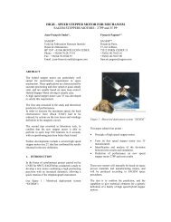
DEVELOPMENT OF A FINE POINTING AND TRIM MECHANISM
DEVELOPMENT OF A FINE POINTING AND TRIM MECHANISM
DEVELOPMENT OF A FINE POINTING AND TRIM MECHANISM

You also want an ePaper? Increase the reach of your titles
YUMPU automatically turns print PDFs into web optimized ePapers that Google loves.
<strong>DEVELOPMENT</strong> <strong>OF</strong> A <strong>FINE</strong> <strong>POINTING</strong> <strong>AND</strong> <strong>TRIM</strong> <strong>MECHANISM</strong><br />
Aurèle Vuilleumier (1) , Max Eigenmann (1) , Arvid Bergander (2) , Thierry Blais (3) , Lucio Scolamiero (4)<br />
(1) RUAG Space, Schaffhauserstrasse 580, CH-8052 Zürich, Switzerland, Email: aurele.vuilleumier@ruag.com,<br />
max.eigenmann@ruag.com<br />
(2) HTS GmbH, Am Glaswerk 6, D-01640 Coswig,Germany, Email: arvid.bergander@htsdd.de<br />
(3) EADS Astrium Satellites, 31 Avenue des Cosmonautes,F-31402 Toulouse, Email: thierry.blais@astrium.eads.net<br />
(4) ESA ESTEC, Postbus 299, 2200 AG Noordwijk, The Netherlands, Email: Lucio.Scolamiero@esa.int<br />
ABSTRACT<br />
An overview is given of the antenna fine pointing and<br />
trim mechanism (FPTM) to be used for future<br />
geostationary telecom satellites operating with narrow<br />
beam coverage. The development goal is to reach TRL-<br />
5 (Technical Readiness Level according to [1]) by<br />
2012.<br />
The FPTM baseline is defined as a two axis mechanism<br />
based on flexible hinges and a linear piezo-electric<br />
actuator. The FPTM shall provide a pointing range of<br />
±2 deg around two axes. A typical operational life of<br />
15 years is targeted.<br />
The FPTM development foresees improvements over<br />
current reflector pointing mechanisms as it shall<br />
provide higher pointing resolution (< 0.002 deg) and<br />
pointing accuracy eliminate backlash and reduce<br />
hysteresis, while meeting current levels for power<br />
consumption volume and stiffness.<br />
1. INTRODUCTION<br />
Multibeam satellites mainly using Ku or Ka-band<br />
systems require high pointing accuracy and resolution<br />
(0.005 deg). Conventional mechanisms use stepper<br />
motors which introduce backlash and hysteresis into<br />
the pointing budget. There is a need coming from<br />
future multimedia telecommunication platforms to<br />
increase resolution and depointing correction rates.<br />
The FPTM development lead by RUAG Space<br />
Switzerland, takes into account future mission<br />
requirements by formally engaging Astrium SAS to<br />
participate in the definition of future antenna fine<br />
pointing requirements.<br />
Applying piezo-electric actuator technology the FPTM<br />
development seeks to provide a technical solution for<br />
future reflector antenna pointing needs.<br />
2. SCOPE of <strong>DEVELOPMENT</strong><br />
In order for the FPTM to achieve TRL5 status it is<br />
necessary to consolidate the future pointing needs with<br />
satellite platform primes. While Astrium SAS has been<br />
contractually engaged to provide support in the<br />
definition of the FPTM pointing requirements, TAS<br />
_________________________________________________<br />
‘14th European Space Mechanisms & Tribology Symposium – ESMATS 2011’<br />
Constance, Germany, 28–30 September 2011<br />
451<br />
France has also been involved to comment before<br />
finalizing the FPTM design requirements.<br />
After consolidation of requirements has been<br />
accomplished, a trade-off of designs is being conducted<br />
in May/June 2011 to select a baseline mechanical and<br />
actuator concept. During the following preliminary<br />
design phase, a bread board test will confirm piezo<br />
actuator life time and performance. In addition reflector<br />
and S/C integration aspects will be studied. In<br />
particular a HDRM concept will be suggested and a<br />
first estimate of launch loads will be made. It is<br />
expected that these results can already be presented at<br />
the ESMATS 2011.<br />
The design will then be detailed by HTS GmbH,<br />
Dresden, incorporating test results and detailed<br />
analysis. As a result an EM of the FPTM will be<br />
manufactured and subject to a qualification test<br />
programme according to general ECSS [2] limits.<br />
3. FPTM REQUIREMENTS<br />
An effort was made to define an envelope of<br />
requirements which would be able to cover two major<br />
satellite platform configurations (Cassegrain Fig. 1 and<br />
Single-Offset Fig. 2).<br />
Figure 1. Cassegrain Configuration with Main (D=5m)<br />
and Sub Reflector (D=2m).
Figure 2. Single Offset Configuration with Main<br />
Reflector (D=5m).<br />
As a baseline the FPTM shall be side mounted in order<br />
not to exceed current reflector stacking envelopes in<br />
launch configuration. This is applicable to both<br />
reflector configurations.<br />
As a result of the collaboration with Astrium SAS and<br />
the comments supplied by TAS the key requirements<br />
for the FPTM are summarized in Tab. 1:<br />
Table 1. FPTM Key Requirements.<br />
Requirement Description Target Value<br />
Pointing range ± 2.0 deg<br />
Pointing Accuracy ± 0.001 deg<br />
Pointing Resolution ± 0.001<br />
Pointing Speed 24 mdeg/s<br />
Life Time (cycles) 2.5 mio<br />
Life Time (travel deg) 870’000<br />
Environmental Temperature -185°C to +165°C<br />
Translational Stiffness 1.5 10 5 N/m<br />
Rotational Stiffness 2.0 10 4 Nm/rad<br />
4. FPTM DESIGN CONCEPTS<br />
Two design concepts based on flexible elements are<br />
currently being evaluated. One of which will be<br />
selected to be manufactured and tested as an<br />
Engineering Model (EM). Neither of the concepts<br />
require lubrication and can easily operate in ambient<br />
atmospheric conditions for ground testing as well as<br />
vacuum.<br />
The FPTM is to be placed between reflector antenna<br />
and reflector deployment mechanism. As such the sole<br />
function of the FPTM is to fine point / trim the<br />
orientation of the reflector antenna. Both design<br />
concepts are capable of fulfilling the key requirements<br />
mentioned above (Tab. 1) hence catering for both S/C<br />
reflector configurations (Fig. 1 & Fig. 2).<br />
Thermal decoupling from the reflector is foreseen with<br />
limited thermal flux allowed toward the S/C. The<br />
FPTM development will also provide a thermal control<br />
concept in order to deal with the general environmental<br />
conditions of a GEO orbit.<br />
Both design concepts have integrated capacitive<br />
sensors in order to determine rotational position. These<br />
452<br />
will be used for performance test purposes on ground<br />
but may also be integrated at S/C system level if<br />
needed for closed loop control.<br />
Both concepts will be able to provide the necessary<br />
holding force in powered and unpowered status.<br />
4.1. Monolithic Design Concept<br />
The monolithic design concept has small flexible<br />
elements located at the diagonals of the cubus (Fig. 3).<br />
This configuration provides excellent stiffness and very<br />
little cross talk between the rotational axes in<br />
comparison to the trapezoidal design concept.<br />
The design is compact and can be modularly fit<br />
between reflector antenna and reflector deployment<br />
mechanism.<br />
The design may easily be adapted to accommodate an<br />
HDRM should the holding forces of the actuator show<br />
this to be necessary during launch.<br />
I/F Plane (reflector deployment<br />
mechanism)<br />
2. Rotational Axis<br />
Figure 3. FPTM Monolithic Design Concept.<br />
4.2. Trapezoidal Design Concept<br />
1. Rotational Axis<br />
The trapezoidal design concept extends the flexible<br />
blade concept and consists of two interconnected<br />
rotating planes (Fig. 3). The I/F plane movement is<br />
cinematically a combination of linear and angular<br />
displacements. While this may seem to be a<br />
disadvantage the linear displacements may be used in<br />
order to reduce focal depointing, a great advantage<br />
over the monolithic design.<br />
I/F Plane (reflector)<br />
2. Rotational Axis<br />
Piezo-Actuators<br />
I/F Plane (reflector)<br />
1. Rotational Axis<br />
I/F Plane (reflector deployment mechanism)<br />
Figure 4. FPTM Trapezoidal Design Concept.
While the trapezoidal design concept is lighter weight<br />
then the monolithic design concept it may prove<br />
difficult to achieve stiffness requirement and<br />
implement an HDRM if deemed necessary.<br />
4.3. Motorization Concept<br />
While several piezo-actuator concepts are available<br />
walking-piezo type actuators provide the best<br />
performance in terms of holding force (unpowered),<br />
travel range and operating temperature. Using walkingpiezo<br />
type actuators will also be able to profit from the<br />
experience RUAG Space has in designing piezo<br />
actuator drive electronics compatible to S/C platform<br />
needs, see [3], [4] and [5].<br />
4.4. Drive Electronics<br />
While the development of the drive electronics is not in<br />
the scope of the FPTM development project, a general<br />
concept has been derived based on the electronics<br />
developed by RUAG for LISA PAAM (Fig. 5).<br />
Compatibility to S/C platform electronics is given in<br />
the example of the EUROSTAR 3000 platform.<br />
The drive electronics are designed to communicate<br />
with S/C system electronics. At system level a number<br />
of steps is commanded defined by the pointing<br />
resolution. The FPTM drive electronics uses a closed<br />
loop control system, where the integrated angular<br />
sensor feed backs are used to accurately drive the<br />
FPTM to the required heading.<br />
Setpoint<br />
Motion<br />
Controller<br />
Axis 1<br />
Interface<br />
Controller<br />
Motion<br />
Controller<br />
Axis 2<br />
Step & FWD/RWD<br />
?POS<br />
Step & FWD/RWD<br />
?POS<br />
Driver<br />
Position 1<br />
Position 2<br />
Driver<br />
Position 1<br />
Position 2<br />
Figure 5. FPTM Drive Electronics Concept.<br />
5. OUTLOOK<br />
The requirement consolidation phase is currently<br />
coming to closure while first trade-off studies between<br />
the two mechanical design concepts and motorisation<br />
possibilities have begun.<br />
Several technical issues still need to be addressed<br />
before the piezo-based technology may be considered a<br />
stepper motor replacement. Critical interest is given to:<br />
- Costs to develop space qualified drive electronics<br />
- Power Supply<br />
- Mass<br />
- Stiffness<br />
M<br />
M<br />
453<br />
5.1. Commercial Market<br />
While current stepper motor solutions have drive<br />
electronics which are already integrated in many<br />
commercial telecom platforms, the specific power<br />
supply requirements of the piezo-actuators (high<br />
voltages) require new electrical interfaces to be<br />
developed and space proven.<br />
The performance outcome of the piezo based solution<br />
shall provide sufficient improvements in terms of<br />
resolution, backlash, hysteresis and life-time in order to<br />
justify the development costs of the electronics.<br />
RUAGs business case for the FPTM developed<br />
together with satellite primes is promising, especially<br />
with regard to the coming future commercial telecom<br />
platforms, which are currently being evaluated in the<br />
frame of early concept studies both at Astrium as well<br />
as Thales.<br />
6. NOTES<br />
This paper will be presented at the poster session of<br />
ESMATS 2011 in Constance.<br />
7. REFERENCES<br />
1. ESA TEC-SHS (2008). Technology Readiness<br />
Levels Handbook for Space Applications, TEC-<br />
SHS/5551/MG/ap Iss1 Rev6.<br />
2. ESA Publications. (2002). Space Engineering<br />
Testing, ECSS-E-10-03A<br />
3. Simon Henein et al (2009), Design and Development<br />
of the Point Ahead Angle Mechanism for the Laser<br />
Interferometer Space Antenna, ESMATS 2009<br />
proceedings<br />
4. Pierre-Alain Mäusli et al, Development of a Novel<br />
Piezo Actuated Release Mechanism, ESMATS<br />
2007 proceedings<br />
5. Andreas Neukom et al (2009), Testing and Lessons<br />
Learnt of LISA GPRM, ESMATS 2009<br />
proceedings