mtg scan mechanism predevelopment: design & performance
mtg scan mechanism predevelopment: design & performance
mtg scan mechanism predevelopment: design & performance

You also want an ePaper? Increase the reach of your titles
YUMPU automatically turns print PDFs into web optimized ePapers that Google loves.
MTG SCAN MECHANISM PREDEVELOPMENT: DESIGN & PERFORMANCE<br />
J Vinals (1) , F Valls (1) , J Lozano (1) , F Faure (2) , Th Blais (2) , H Langenbach (3)<br />
(1) SENER Ingenieria y Sistemas, Av. Zugazarte 56, 48930 – Getxo (Spain), Email: javier.vinals@sener.es<br />
(2) ASTRIUM SAS, 31 rue des Cosmonautes - 31402 Toulouse (France), Email: thierry.blais@astrium.eads.net<br />
(3) ASTRIUM GmbH, Claude-Dornier-Straße, 88090 Immenstaad (Germany), Email:<br />
herald.langenbach@astrium.eads.net<br />
ABSTRACT<br />
The MTG instruments are located on a new generation<br />
of GEO SC, 3 axes stabilized. The <strong>scan</strong>ning of the<br />
Earth along the E/W and the S/N directions shall be<br />
ensured by the Scan Mechanisms located ahead the<br />
Instruments, corresponding to challenging pointing<br />
requirements. Key requirements are: <strong>scan</strong> angular<br />
velocity stability (accurate slope and low jitter),<br />
angular pointing restitution accuracy (angular pointing<br />
knowledge) and overall pointing position accuracy<br />
with respect to the commanded position. All these<br />
<strong>performance</strong>s are in the µrad – or even sub µrad - range<br />
over a wide angular stroke, corresponding to<br />
challenging capabilities.<br />
In order to secure the MTG development on these<br />
topics, pre-development activities were initiated under<br />
ESA funding, one development was being completed<br />
by SENER under ASTRIUM prime contractor ship<br />
(France and finally Germany). SENER subcontracted<br />
CEDRAT for motor development and TNO as<br />
interferometer and optical consultant, meanwhile<br />
ASTRIUM subcontracted the encoder activity to<br />
CODECHAMP.<br />
The <strong>performance</strong>s finally demonstrated by the<br />
Breadboard indicate how the target <strong>performance</strong>s are<br />
achieved, together with the lessons learnt which are of<br />
paramount importance to further secure the<br />
development of the MTG mission.<br />
1. MTG BACKGROUND WITH RESPECT TO<br />
THE SCAN MECHANISM<br />
During the MTG Phase A, FCI & IRS instruments<br />
<strong>design</strong>s were progressively worked out. The (bi axis)<br />
Scan Mechanism specifications were refined and<br />
candidate concepts proposed – in line with the<br />
instrument concepts - different from TAS and<br />
ASTRIUM.<br />
Based on limited relevant heritage, the Scan<br />
Mechanism low TRL was considered as a possible risk<br />
for the overall MTG development. Preliminary<br />
activities were decided by ESTEC, aiming at<br />
_________________________________________________<br />
‘14th European Space Mechanisms & Tribology Symposium – ESMATS 2011’<br />
Constance, Germany, 28–30 September 2011<br />
29<br />
developing breadboards consistent with both<br />
instrument activities (TAS & ASTRIUM).<br />
The BB <strong>design</strong> was focused to be representative of the<br />
most critical FM aspects, in particular E/W<br />
<strong>performance</strong>s. BB detailed <strong>design</strong> was started only<br />
after having settled the major representativity aspects<br />
with respect to FM<br />
The BB industrial activities were initiated reflecting the<br />
baseline industrial organization. For the FCI Scan<br />
Mechanism, SENER is the ASTRIUM key partner<br />
2. STUDY OBJECTIVES AND OVERALL<br />
LOGIC<br />
For the study and overall logic, two parallel flows were<br />
followed, one as a reference <strong>design</strong> (the FM concept<br />
focused on the BB development), and the other one<br />
substantiated by key technologies consolidation.<br />
Some novel verification aspects required early<br />
preparation as the metrology, needed for the BB but<br />
also suitable for the FM development.<br />
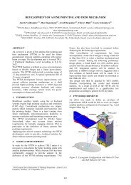
Figure 1. Top-down requirements derivation.
3. MECHANISM FLIGHT DESIGN CONCEPT<br />
The driving technical requirements derived from<br />
instrument specification are:<br />
- Scanning accuracy (stability): "The E/W <strong>scan</strong>ning<br />
accuracy shall be such that 68,3% (1 σ) of the PTV<br />
errors are lower than 1.6 µrad (target 0.58 µrad)<br />
over 203 ms."<br />
- Pointing Restitution: "For each <strong>scan</strong>ned line, the<br />
E/W <strong>scan</strong>ning angle knowledge / restitution<br />
accuracy shall be better than:<br />
o Bias < 0.5 µrad. Error average over<br />
the <strong>scan</strong> range.<br />
o Jitter < 0.5 µrad (1 σ).<br />
This is the error between the actual pointing angle<br />
and the associated measurement / restitution. This<br />
accuracy can include proper processing to be<br />
specified and/or applied by the Scan Mechanism<br />
responsible based on the knowledge of the Scan<br />
Mechanism components <strong>performance</strong>s (encoder<br />
characterization, filtering, calibration & mapping<br />
as necessary)"<br />
- Overall position accuracy (“achieved” versus<br />
commanded): "the maximum absolute angular<br />
error within the whole <strong>scan</strong> range shall be<br />
lower or equal to 100 µrad"<br />
The development priority was to rely on existing<br />
heritage and further re-enforce European technologies:<br />
- Using results of previous technology <strong>predevelopment</strong>s<br />
(GSTP)<br />
- Taking benefit of European capabilities in critical<br />
aspects (sensors, flexures)<br />
The major components that have been developed<br />
during the BB phase are:<br />
- Guiding: Flexural pivots <strong>design</strong>ed and<br />
manufactured by SENER (HAFHA heritage)<br />
- Actuator: Resulting from previous GSTP<br />
development with encouraging results that were<br />
further optimised and associated hardware<br />
implemented:<br />
Selection of a LAT <strong>design</strong> as reference<br />
<strong>design</strong> – for FM & BB<br />
Intensive trade off and optimisation of<br />
alternatives solutions studied to<br />
consolidate the selection for FM<br />
- Angular position sensor: CODECHAMP high<br />
resolution/high accuracy optical encoder (24-bits).<br />
4. REALIZED ELEGANT BREADBOARD<br />
MECHANISM DESIGN<br />
The EBB <strong>mechanism</strong> <strong>design</strong> was derived from FM<br />
concept and focused on E/W <strong>performance</strong>s. The key<br />
<strong>design</strong> requirements are the E/W pointing<br />
<strong>performance</strong>s, and the mechanical environment -<br />
frequency response (mechanical), including mechanical<br />
<strong>design</strong> verification through vibration tests.<br />
The EBB representativity is limited concerning the<br />
following aspects:<br />
30<br />
- S/N axis functions. Limited to structure (locking &<br />
ball bearings) for mechanical vibrations.<br />
- E/W anti-rotation device: manually operated<br />
- Electronics front end & control = industrial rated<br />
drivers + DSpace<br />
- Materials not necessarily fully representative for<br />
non-critical components<br />
The mirror is represented by a dummy– IFs (mounting<br />
principle), mass and stiffness representative.<br />
In the next figure it is described the main features of<br />
the EBB <strong>design</strong>. The first step was the accommodation<br />
analysis of two main <strong>mechanism</strong> architectures that<br />
were valuable and be compared:<br />
- localised: both the motor and the encoder on the<br />
same side<br />
- delocalised: motor on one side, encoder on the<br />
other side<br />
The delocalised option was selected due to the<br />
following many/major advantages:<br />
- Simpler, safer <strong>design</strong>, manufacturing, assembly<br />
and modularity<br />
- More compact and quite symmetrical<br />
configuration<br />
- Better E/W mass balance, avoiding unbalanced,<br />
with masses on the both sides of the mirror<br />
Dummy mirror<br />
Encoder<br />
4.1. Flexural pivots<br />
E/W axis<br />
Motor<br />
Figure 2. EBB E/W <strong>design</strong>.<br />
Yoke<br />
N/S axis<br />
The flexural pivot developed is based on HAFHA<br />
<strong>design</strong>, mainly, including some new features as higher<br />
load case (supports the whole load range) or three<br />
blades configuration that prevents the pivot from<br />
suffering an additional stress generated by a bending
moment when loading it radially. One important<br />
advantage is the manufacturing in one piece that<br />
implies no welding between parts.<br />
The <strong>design</strong> of the FP is focused on the following<br />
features:<br />
- supporting high loads<br />
- mechanical IF efficiency and robustness<br />
- trade off supported by early vibration tests<br />
- FEM iterations and refinement<br />
- component-level characterisation: stiffness &<br />
hysteresis, mechanical allowables (axial, radial<br />
traction, radial buckling) and life test (> 20 million<br />
cycles demonstrated)<br />
Figure 3. Flexural pivot (left) and section view<br />
showing the 3 blades crossing (right).<br />
4.2. Angular position sensing<br />
The angular position sensing has very stringent<br />
requirements applicable. The baseline is a European<br />
source with high in-orbit heritage experienced:<br />
CODECHAMP Encoder including embedded<br />
electronics whose communication interface is a<br />
protocol based on RS422.<br />
Early characterization has been performed at encoder<br />
level, in various configurations to ensure full<br />
traceability of guiding properties effects. The main<br />
characterized parameters have been the harmonics<br />
which are related to the sensor knowledge / restitution.<br />
5. TEST PLAN OVERVIEW<br />
The objective of the EBB test plan was to mitigate<br />
prior to Phase B E/W <strong>scan</strong> development technological<br />
risks, as the mechanical <strong>design</strong> verification through<br />
vibration tests or the E/W <strong>scan</strong> <strong>performance</strong><br />
assessment:<br />
- Verification of pointing <strong>performance</strong>s using an<br />
independent metrology system – not relying only<br />
on the encoder data:<br />
Early validation of the metrology system<br />
(tuning, sensitivities) with several<br />
toolings<br />
Demonstrate suitability for BB, DM, EM<br />
& FM – starting with 1 axis for BB<br />
- E/W <strong>scan</strong> <strong>performance</strong> assessment by incremental<br />
validations:<br />
31<br />
Individual assessment of each key<br />
technology building block<br />
Components assembled into a<br />
representative breadboard (SMBB)<br />
Closed-loop tests to validate E/W <strong>scan</strong><br />
<strong>performance</strong><br />
- Mechanical <strong>design</strong> verification through vibration<br />
tests<br />
The BB integration was performed by incremental<br />
models in terms of representativity:<br />
- BBM1: Structural model representative of launch<br />
configuration<br />
- BBM2: Encoder and actuator open-loop<br />
characterisation with motor drive electronics<br />
(torque shape versus current, noise, quantification,<br />
harmonics)<br />
- SMBB: Full E/W <strong>scan</strong> breadboard, for closed-loop<br />
tests<br />
The encoder guiding and mechanical coupling with<br />
fine angular metrology system has been performed by<br />
steps:<br />
- Step 0: Encoder foot print measured at<br />
CODECHAMP on ball bearings<br />
- Step 1: Encoder mounted with ball bearings (idem)<br />
+ motor + metrology for first check of encoder &<br />
metrology. Comparison with Step 0.<br />
- Step 2: Encoder on SMBB to check effect of flex<br />
pivots<br />
Open-loop characterization has been tested on encoder<br />
& motor: Encoder bench mounted on ball bearings.<br />
LAT motor prototype + laboratory-grade electronics to<br />
command different positions and ramp or sine profiles<br />
to allow full encoder characterization.<br />
Laboratorygrade<br />
LAT<br />
Motor driver<br />
Motor<br />
Encoder<br />
Real-time system<br />
Data acquisition & storage<br />
LAT motor drive<br />
Figure 4. Open-loop characterization<br />
A synchronous acquisition of encoder & metrology<br />
was performed, first version of real-time electronics.<br />
5.1. Realized Test and Hardware Models<br />
The test plan rationale was as follows:<br />
- OGSE set up & tuning<br />
- BBM2: Building blocks for elementary<br />
characterisation / testing (pivots properties & life),<br />
Fine angular<br />
metrology
isostatic mounts, encoder, actuator (torque defects<br />
& thermal), motor driver electronics (proto)<br />
- SMBB: Open loop tests. Correlation with<br />
predictions (Simulink). Models refinement and real<br />
time controllers comparison<br />
- SMBB: Closed loop tests (FCI profile & IRS<br />
profile (“step & stare”))<br />
- BBM1: Vibration tests, specific instrumentation<br />
for the critical items (allowables oriented)<br />
Figure 5. Test plan rationale<br />
Figure 6. EBB MTG FCI SM in vibration test<br />
5.2. OGSE set-up<br />
The metrology equipment used (and available at<br />
SENER facilities) in the EBB MTG FCI optical<br />
characterization was:<br />
32<br />
- Interferometers (resolution 0.77nm)<br />
- Retroreflectors<br />
- Autocollimator (resolution 0.2 µrad)<br />
- Theodolite (accuracy 0.5´´)<br />
- Others: laser dielectric mirrors, optical mounts and<br />
active isolators<br />
Figure 7. EBB functional assembly in the OGSE set-up.<br />
The measurement results fully confirm that IFM<br />
system may be considered the adequate metrology<br />
system for the analysis of the EBB E/W movement.<br />
The obtained data show the system accuracy strongly<br />
depends on the setup which was applied during the<br />
measurement.<br />
Metrology system is introducing some errors in large<br />
angle measurements and errors are increasing in<br />
function of measured angular range. Try to distinguish<br />
the origin and estimate its individual value post<br />
processing the final data is very difficult, and the tests<br />
made specifically for this reason were not conclusive.<br />
5.3. Electromechanical actuator<br />
An exhaustive trade-off was performed between<br />
actuator technologies as LAT, BDLC and Voice Coil.<br />
The selected actuator has been a LAT motor related to<br />
a GSTP development (ESA program). The profits of<br />
this technology are the high torque stability and the low<br />
mass.<br />
The actuator tests, which are detailed in the next<br />
paragraph, was focused on calculating the actuator<br />
parameters like torque stability, Kt variability along the<br />
<strong>scan</strong>ning, hysteresis and torque saturation (maximum<br />
torque). Resulting, the torque stability of the actuator is<br />
a good property in the <strong>scan</strong>ning process.
6. MAJOR TEST RESULTS ACHIEVED<br />
6.1. Stability<br />
The stability of realized movement meets the 1.6µrad<br />
(red line) stability spec over 203 ms. the stability error<br />
has been calculated as:<br />
() t = Actual Angle () t − Commanded Angle ( t)<br />
() t = [ max ( Angle Error ( t1)<br />
) − min ( Angle Error ( t1)<br />
) ]<br />
Angle Error<br />
dAngle Error<br />
¬ t1<br />
is between t and t + 203ms<br />
The following figure represents the stability error<br />
during an individual <strong>scan</strong>ning with the requirements:<br />
the limit (in red) and the goal (in orange).<br />
Good repeatability observed in different <strong>scan</strong>nings.<br />
6.2. Restitution<br />
Figure 8. Stability<br />
The encoder includes some high frequency contents<br />
that correspond to spatial errors (“foot print”) of the<br />
encoder. Spatial errors translated into time-frequency,<br />
following the <strong>scan</strong> rate.<br />
33<br />
Figure 9. Encoder error versus reference metrology.<br />
27 mrd/s – 3 kHz<br />
6.3. Accuracy<br />
The 100 µrd overall accuracy requirement is achieved<br />
with margins.<br />
In the figures, the <strong>scan</strong>ning is plotted in blue line (Left<br />
Y-Scale) and the error is in green line (Right Y-Scale).<br />
Each figure is set with different control laws (course on<br />
top and optimized on bottom).<br />
Command (°)<br />
Command (°)<br />
10<br />
Command (°)<br />
5<br />
Error from encoder output (µrd)<br />
0<br />
-5<br />
-10<br />
0 5 10 15 20 25 30 35 40 -50<br />
50<br />
40<br />
30<br />
20<br />
10<br />
0<br />
-10<br />
-20<br />
-30<br />
-40<br />
Scan Error, calculated from IFM corrected angle (µrd)<br />
10<br />
Command (°)<br />
5<br />
Error from IFM corrected angle (µrd)<br />
0<br />
-5<br />
-10<br />
0 5 10 15 20<br />
time(s)<br />
25 30 35 40 -50<br />
50<br />
40<br />
30<br />
20<br />
10<br />
0<br />
-10<br />
-20<br />
-30<br />
-40<br />
7. LESSONS LEARNT<br />
Figure 10. Accuracy<br />
External metrology is mandatory to assess “achieved”<br />
<strong>performance</strong>s - independently of the encoder data. Real<br />
time aspects shall be carefully controlled (sampling<br />
rate, delay effects = velocity dependent).<br />
Some improvements were identified and justified in<br />
terms of alignment – to minimize the magnitude of the<br />
correction. However, current misalignment effects are<br />
observable and are corrected in the metrology<br />
processing by calibration<br />
Error (µrd)<br />
Error (µrd)
No jitter observed on the mirror achieved position @27<br />
mrad/s; sensitivity to be assessed by prediction for<br />
different rates.<br />
Encoder processing to be optimized for the restitution<br />
purpose.<br />
8. ABBREVIATIONS AND ACRONYMS<br />
BB BreadBoard<br />
BDLC Brushless Direct Current<br />
DM Development Model<br />
E/W East / West<br />
EBB Elegant BreadBoard<br />
EM Engineering Model<br />
FCI Flexible Combined Imager<br />
FEM Finite Element model<br />
FM Flight Model<br />
FP Flexural Pivot<br />
GSTP General Support Technology Programme<br />
HAFHA High Accuracy Flexural Hinge Assembly<br />
IF Interface<br />
IFM Interferometer<br />
IRS Infrared Sounding Mission<br />
Kt Motor constant<br />
LAT Limited angle torque<br />
MTG Meteosat Third Generation<br />
N/S North / South<br />
OGSE Optical Ground Support Equipment<br />
PTV Peak To Valley<br />
SM Scan Mechanism<br />
SMBB Structural Model Breadboard<br />
TAS Thales Alenia Space<br />
TRL Technology Readiness Level<br />
9. REFERENCES<br />
1. Z.Q.Zhu, D.Ishak and D.Howe. “Analysis of<br />
Cogging Torque in Brushless Machines Having<br />
Nonuniformly Disttributed Stator Slots and<br />
Stepped Rotor Magnets” IEEE Trans. on Magn.<br />
Vol.41, NO 10, October 2005<br />
2. Du Chunyang, Li Tiecai, Cao Zhengcai. “Accurate<br />
Tracking Control of a Limit Angle Torque Motor”<br />
0-7803-7883-0 2003 IEEE<br />
3. P. Murali Krishna, N. Kannan. “Brushless d.c.<br />
Limited Angle Torque Motor” 0-7803-2795-0<br />
2002 IEEE<br />
4. N.Bencheikh, R. Le Letty, F.Claeyssen, G. Magnac,<br />
G. Migliorero. “Limited angle torque actuator for<br />
fine angular positioning” ACTUATOR 2010,<br />
Messe Bremen Guidelines for Authors, June 2010.<br />
5. I. Santos, I. Ortiz de Zárate, G. Migliorero. “High<br />
accuracy flexural hinge development” ESMATS<br />
2005, 11 th European Space Mechanisms and<br />
Tribology Symposium 2005, 21-23 September<br />
2005, Lucerne, Switzerland, ISBN 92-9092-902-2,<br />
ISSN 0379-6566.<br />
34