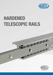
HT221EN_Hardened Telescopic Rails

Create successful ePaper yourself
Turn your PDF publications into a flip-book with our unique Google optimized e-Paper software.
TECHNICAL SPECIFICATIONS<br />
NTA-H, NTS-H, NTSF-H, NTVZ-H, NTUZ-H<br />
DEFLECTION<br />
The deflection is the elastic deformation you can experience at the edge of the opened rail when a load is applied.<br />
With semi-telescopic rails NTA-H, that can partially exit from the rail, the<br />
deflection will depend almost exclusively on the rigidity of the structures<br />
connected to the guide elements.<br />
FRICTION COEFFICIENT<br />
The friction coefficient in normal conditions is equal to 0,01. When the movement of the slider is controlled by a drive system, we recommend<br />
providing a peak motor torque 10 times higher than the standard required due to the process of displacement (see the “Suggestion for a correct<br />
mounting” paragraph). For telescopic rails NTSF-H, NTUZ-H, NTVZ-H the required closing force for letting the slider return to the central position<br />
is increased by the deflection due to the extraction of the moving elements.<br />
SUGGESTIONS FOR A CORRECT MOUNTING<br />
In ball-cages guide systems, the sliding occurs thanks to the simultaneous movement of the slider and the ball-cage: the slider, moved manually<br />
or by a drive system, sets in motion the ball-cage, which will cover half of the stroke done by the slider, until reaching the end-stop.<br />
During the running operation, with the succession of working cycles and consequent motion reversals, imperceptible displacements of the<br />
ball-cage can occur.<br />
This process, that is defined displacement and leads to a gradual reduction of the stroke and consequent dragging of the ball-cage on the<br />
raceways, can be slowed down by limiting speed and acceleration.<br />
The restoration of the proper functioning must be done by setting a forced cycle up to the end stop: when the movement of the slider is commanded<br />
by a drive system, we recommend providing a peak motor torque 10 times higher (friction coefficient in normal condition is 0,01).<br />
Guide systems based on ball-cages are mostly recommended for horizontal movements. Vertical installation is not recommended because the<br />
ball-cage tends to fall by gravity, emphsizing the process of displacement.<br />
We recomend providing an external end stop in order not to only discharge the arrest of the machine on the stopping screw.<br />
The internal end stop are designed to syncronize the cage and inner elements only.<br />
<strong>Rails</strong> mounted in parallel require good alignment between the 2 sides to avoid internal overload and difficulty in the movement.<br />
Size<br />
Chamfer (mm)<br />
NTA28, NTSF28, NTVZ84-17H, NTUZ84-30H 1x45°<br />
NTA43, NTSF43, NTVZ120-28H, NTUZ120-50H<br />
1,5x45°<br />
NTA63, NTSF63, NTVZ208-40H, NTUZ208-69H 1x45°<br />
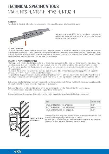
Chamfer in the holes<br />
of the support<br />
The support on which the guide is mounted needs to have holes with chamfer in order<br />
to allow a correct tightening of the countersunk screws.<br />
For each type of telescopic rail, the minimum chamfer is shown in the table above<br />
(telescopic rails not present in table do not require chamfer).<br />
46 |