- Page 1:
Planning Guide 02/2003 Edition Driv
- Page 4 and 5:
3ls SIMODRIVE ® documentation Prin
- Page 6 and 7:
Foreword Definition: Who are qualif
- Page 8 and 9:
Foreword viii ! ! ! 05.01 Note For
- Page 10 and 11:
Foreword ESDS information x Electro
- Page 12 and 13:
xii 02.03 05.01 2.8.3 Line filter p
- Page 14 and 15:
xiv 02.03 05.01 6.6.2 Overvoltage l
- Page 16 and 17:
xvi Space for your notes 02.03 05.0
- Page 18 and 19:
1 1 Overview of the Drive System 1.
- Page 20 and 21:
1 1 Overview of the Drive System 1.
- Page 22 and 23:
1 1 Overview of the Drive System 1.
- Page 24 and 25:
2 2 System Configuration 2.1 Arrang
- Page 26 and 27:
2 2 System Configuration 2.1 Arrang
- Page 28 and 29:
2 2 System Configuration 2.2 Ambien
- Page 30 and 31:
2 2 System Configuration 2.4 Positi
- Page 32 and 33:
2 2 System Configuration 2.5 Power
- Page 34 and 35:
2 2 System Configuration 2.6 Contro
- Page 36 and 37:
2 2 System Configuration 2.6 Contro
- Page 38 and 39:
2 2 System Configuration 2.6 Contro
- Page 40 and 41:
2 2 System Configuration 2.6 Contro
- Page 42 and 43:
2 2 System Configuration 2.7 Infeed
- Page 44 and 45:
2 2 System Configuration 2.7 Infeed
- Page 46 and 47:
2 2 System Configuration 2.7 Infeed
- Page 48 and 49:
2 2 System Configuration 2.7 Infeed
- Page 50 and 51:
2 2 System Configuration 2.8 Line s
- Page 52 and 53:
2 2 System Configuration 2.8 Line s
- Page 54 and 55:
2 2 System Configuration 2.8 Line s
- Page 56 and 57:
2 2 System Configuration 2.8 Line s
- Page 58 and 59:
2 2 System Configuration 2.8 Line s
- Page 60 and 61:
2 2 System Configuration 2.8 Line s
- Page 62 and 63:
3 3 Motor Selection, Position/Speed
- Page 64 and 65:
3 3 Motor Selection, Position/Speed
- Page 66 and 67:
3 3 Motor Selection, Position/Speed
- Page 68 and 69:
3 3 Motor Selection, Position/Speed
- Page 70 and 71:
3 3 Motor Selection, Position/Speed
- Page 72 and 73:
3 3 Motor Selection, Position/Speed
- Page 74 and 75:
3 3 Motor Selection, Position/Speed
- Page 76 and 77:
3 3 Motor Selection, Position/Speed
- Page 78 and 79:
3 3 Motor Selection, Position/Speed
- Page 80 and 81:
3 3 Motor Selection, Position/Speed
- Page 82 and 83:
3 3 Motor Selection, Position/Speed
- Page 84 and 85:
3 3 Motor Selection, Position/Speed
- Page 86 and 87:
3 3 Motor Selection, Position/Speed
- Page 88 and 89:
4 4 Power Modules Power module, int
- Page 90 and 91:
4 4 Power Modules 4.1 Technical dat
- Page 92 and 93:
4 4 Power Modules 4.1 Technical dat
- Page 94 and 95:
4 4 Power Modules 4.2 Current de-ra
- Page 96 and 97:
4 4 Power Modules 4.2 Current de-ra
- Page 98 and 99:
4 4 Power Modules 4.2 Current de-ra
- Page 100 and 101:
4 4 Power Modules 4.2 Current de-ra
- Page 102 and 103:
4 4 Power Modules 4.3 Load duty cyc
- Page 104 and 105:
4 4 Power Modules 4.4 Interface ove
- Page 106 and 107:
5 5 Control Modules 02.03 05.01 Tab
- Page 108 and 109:
5 5 Control Modules 5.1 Feed contro
- Page 110 and 111:
5 5 Control Modules 5.1 Feed contro
- Page 112 and 113:
5 5 Control Modules 5.1 Feed contro
- Page 114 and 115:
5 5 Control Modules 5.2 Feed contro
- Page 116 and 117:
5 5 Control Modules 5.3 Resolver co
- Page 118 and 119:
5 5 Control Modules 02.03 05.01 5.3
- Page 120 and 121:
5 5 Control Modules 5.4 Main spindl
- Page 122 and 123:
5 5 Control Modules 5.4 Main spindl
- Page 124 and 125:
5 5 Control Modules 5.5 Induction m
- Page 126 and 127:
5 5 Control Modules 5.5 Induction m
- Page 128 and 129:
5 5 Control Modules 02.03 05.01 5.5
- Page 130 and 131:
5 5 Control Modules 02.03 05.01 5.6
- Page 132 and 133:
5 5 Control Modules 5.6 Drive contr
- Page 134 and 135:
5 5 Control Modules 02.03 05.01 5.6
- Page 136 and 137:
5 5 Control Modules 02.03 05.01 5.6
- Page 138 and 139:
5 5 Control Modules 02.03 05.01 5.7
- Page 140 and 141:
5 5 Control Modules 02.03 05.01 5.7
- Page 142 and 143:
5 5 Control Modules 02.03 05.01 5.7
- Page 144 and 145:
5 5 Control Modules 02.03 05.01 5.7
- Page 146 and 147:
5 5 Control Modules 02.03 05.01 5.7
- Page 148 and 149:
5 5 Control Modules 5.7 Control mod
- Page 150 and 151:
5 5 Control Modules 02.03 05.01 5.7
- Page 152 and 153:
5 5 Control Modules 02.03 05.01 5.8
- Page 154 and 155:
5 5 Control Modules 02.03 05.01 5.8
- Page 156 and 157:
5 5 Control Modules 08.02 05.01 5.8
- Page 158 and 159:
5 5 Control Modules 5.8 Control mod
- Page 160 and 161:
5 5 Control Modules 5.9 Control mod
- Page 162 and 163:
5 5 Control Modules 5.9 Control mod
- Page 164 and 165:
5 5 Control Modules 02.03 05.01 5.9
- Page 166 and 167:
5 5 Control Modules 5.9 Control mod
- Page 168 and 169:
5 5 Control Modules 5.9 Control mod
- Page 170 and 171:
5 5 Control Modules 5.10 Control mo
- Page 172 and 173:
5 5 Control Modules 5.10 Control mo
- Page 174 and 175:
5 5 Control Modules 5.10 Control mo
- Page 176 and 177:
5 5 Control Modules 5.10 Control mo
- Page 178 and 179:
6 6 Infeed Modules 6-178 05.01 The
- Page 180 and 181:
6-180 © Siemens AG 2003 All rights
- Page 182 and 183:
6 6 Infeed Modules 08.02 05.01 6.1
- Page 184 and 185:
6 6 Infeed Modules 02.03 05.01 6.1
- Page 186 and 187:
6 6 Infeed Modules 6.2 Power module
- Page 188 and 189:
6 6 Infeed Modules 6.3 Technical da
- Page 190 and 191:
6 6 Infeed Modules 02.03 05.01 6.3
- Page 192 and 193:
6 6 Infeed Modules 6.3 Technical da
- Page 194 and 195:
6 6 Infeed Modules 6.3 Technical da
- Page 196 and 197:
6 6 Infeed Modules 02.03 05.01 6.4
- Page 198 and 199:
6 6 Infeed Modules 02.03 05.01 6.4
- Page 200 and 201:
6 6 Infeed Modules 6.5 Monitoring m
- Page 202 and 203:
6 6 Infeed Modules 6.5 Monitoring m
- Page 204 and 205:
6 6 Infeed Modules 6.5 Monitoring m
- Page 206 and 207:
6 6 Infeed Modules 02.03 05.01 6.5
- Page 208 and 209:
6 6 Infeed Modules 6.5 Monitoring m
- Page 210 and 211:
6 6 Infeed Modules 6.6 DC link opti
- Page 212 and 213:
6 6 Infeed Modules 6.6 DC link opti
- Page 214 and 215:
6 6 Infeed Modules 6.6 DC link opti
- Page 216 and 217:
6 6 Infeed Modules 02.03 05.01 6.6
- Page 218 and 219:
6 6 Infeed Modules 6.6 DC link opti
- Page 220 and 221:
6 6 Infeed Modules 6.6 DC link opti
- Page 222 and 223:
6 6 Infeed Modules 6.6 DC link opti
- Page 224 and 225:
6 6 Infeed Modules 6.6 DC link opti
- Page 226 and 227:
7 7 Line Supply Connection 02.03 05
- Page 228 and 229:
7 7 Line Supply Connection 02.03 05
- Page 230 and 231:
7 7 Line Supply Connection 7.1 Line
- Page 232 and 233:
7 7 Line Supply Connection 02.03 05
- Page 234 and 235:
7 7 Line Supply Connection 02.03 05
- Page 236 and 237:
7 7 Line Supply Connection 02.03 05
- Page 238 and 239:
7 7 Line Supply Connection 02.03 05
- Page 240 and 241:
7 7 Line Supply Connection 02.03 05
- Page 242 and 243:
7 7 Line Supply Connection 02.03 05
- Page 244 and 245:
7 7 Line Supply Connection 02.03 05
- Page 246 and 247:
8 Supplementary System Components 8
- Page 248 and 249:
9 9 Important Circuit Information 9
- Page 250 and 251:
9 9 Important Circuit Information 9
- Page 252 and 253:
9 9 Important Circuit Information 9
- Page 254 and 255:
9 9 Important Circuit Information 9
- Page 256 and 257:
9 9 Important Circuit Information 9
- Page 258 and 259:
9 9 Important Circuit Information 0
- Page 260 and 261:
9 9 Important Circuit Information 9
- Page 262 and 263:
9 9 Important Circuit Information 9
- Page 264 and 265:
9 9 Important Circuit Information 9
- Page 266 and 267:
9 9 Important Circuit Information 9
- Page 268 and 269:
9 9 Important Circuit Information 0
- Page 270 and 271:
9 9 Important Circuit Information 0
- Page 272 and 273:
9 9 Important Circuit Information 0
- Page 274 and 275: 9 9 Important Circuit Information 0
- Page 276 and 277: 9 9 Important Circuit Information 0
- Page 278 and 279: 9 9 Important Circuit Information 9
- Page 280 and 281: 9 9 Important Circuit Information 9
- Page 282 and 283: 9 9 Important Circuit Information 9
- Page 284 and 285: 9 9 Important Circuit Information 0
- Page 286 and 287: 9-286 © Siemens AG 2003 All rights
- Page 288 and 289: 9-288 © Siemens AG 2003 All rights
- Page 290 and 291: 9-290 © Siemens AG 2003 All rights
- Page 292 and 293: 9-292 © Siemens AG 2003 All rights
- Page 294 and 295: 9-294 © Siemens AG 2003 All rights
- Page 296 and 297: 9 9 Important Circuit Information 0
- Page 298 and 299: 9 9 Important Circuit Information 0
- Page 300 and 301: 9 9 Important Circuit Information 0
- Page 302 and 303: 9 9 Important Circuit Information 0
- Page 304 and 305: 9 9 Important Circuit Information 0
- Page 306 and 307: 9 9 Important Circuit Information 9
- Page 308 and 309: 9 9 Important Circuit Information 9
- Page 310 and 311: 9 9 Important Circuit Information 9
- Page 312 and 313: 9 9 Important Circuit Information 9
- Page 314 and 315: 9 9 Important Circuit Information 9
- Page 316 and 317: 9 9 Important Circuit Information 9
- Page 318 and 319: 9 9 Important Circuit Information 9
- Page 320 and 321: 9 9 Important Circuit Information 9
- Page 322 and 323: 9 9 Important Circuit Information 9
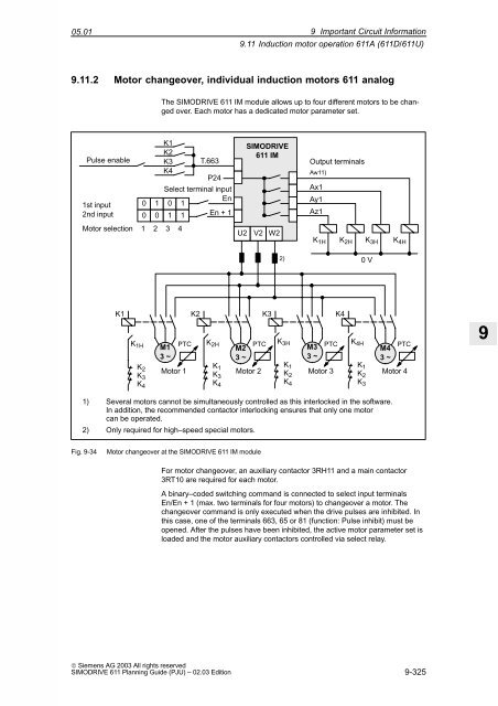
- Page 326 and 327: 9 9 Important Circuit Information 9
- Page 328 and 329: 9 9 Important Circuit Information 9
- Page 330 and 331: 9 9 Important Circuit Information 9
- Page 332 and 333: 9-332 © Siemens AG 2003 All rights
- Page 334 and 335: 9 9 Important Circuit Information 9
- Page 336 and 337: 9 9 Important Circuit Information 9
- Page 338 and 339: 9 9 Important Circuit Information 9
- Page 340 and 341: 10 10 Cabinet Design and EMC 02.03
- Page 342 and 343: 10 10 Cabinet Design and EMC 10.1 I
- Page 344 and 345: 10 10 Cabinet Design and EMC 02.03
- Page 346 and 347: 10 10 Cabinet Design and EMC 02.03
- Page 348 and 349: 10 10 Cabinet Design and EMC 10.1 I
- Page 350 and 351: 10 10 Cabinet Design and EMC 02.03
- Page 352 and 353: 10 10 Cabinet Design and EMC 10.3 S
- Page 354 and 355: 11 11 Connection Diagrams 02.03 05.
- Page 356 and 357: 11 11 Connection Diagrams 02.03 05.
- Page 358 and 359: 11-358 © Siemens AG 2003 All right
- Page 360 and 361: 12 12 Dimension Drawings 12-360 05.
- Page 362 and 363: 12 12 Dimension Drawings Fig. 12-2
- Page 364 and 365: 12 12 Dimension Drawings Fig. 12-4
- Page 366 and 367: 12 12 Dimension Drawings Fig. 12-6
- Page 368 and 369: 12 12 Dimension Drawings Fig. 12-8
- Page 370 and 371: 12 12 Dimension Drawings 4 5 6 7 8
- Page 372 and 373: 12 12 Dimension Drawings 4 5 6 7 8
- Page 374 and 375:
12 12 Dimension Drawings 1 2 3 4 5
- Page 376 and 377:
12 12 Dimension Drawings 1 2 3 4 5
- Page 378 and 379:
12 12 Dimension Drawings 4 5 6 7 8
- Page 380 and 381:
12 12 Dimension Drawings 02.03 05.0
- Page 382 and 383:
12 12 Dimension Drawings 12-382 100
- Page 384 and 385:
12 12 Dimension Drawings 12-384 6SN
- Page 386 and 387:
12 12 Dimension Drawings Fig. 12-26
- Page 388 and 389:
12 12 Dimension Drawings 12-388 6SN
- Page 390 and 391:
12 12 Dimension Drawings Fig. 12-30
- Page 392 and 393:
12 12 Dimension Drawings Fig. 12-32
- Page 394 and 395:
12 12 Dimension Drawings Fig. 12-34
- Page 396 and 397:
12 12 Dimension Drawings Fig. 12-36
- Page 398 and 399:
12 12 Dimension Drawings 12-398 100
- Page 400 and 401:
12 12 Dimension Drawings 02.03 05.0
- Page 402 and 403:
12-402 © Siemens AG 2003 All right
- Page 404 and 405:
12-404 © Siemens AG 2003 All right
- Page 406 and 407:
12-406 © Siemens AG 2003 All right
- Page 408 and 409:
12-408 © Siemens AG 2003 All right
- Page 410 and 411:
12 12 Dimension Drawings Fig. 12-50
- Page 412 and 413:
12 12 Dimension Drawings 1 2 3 4 5
- Page 414 and 415:
12 12 Dimension Drawings Fig. 12-54
- Page 416 and 417:
12-416 © Siemens AG 2003 All right
- Page 418 and 419:
A A EC Declaration of Conformity 02
- Page 420 and 421:
A A EC Declaration of Conformity 02
- Page 422 and 423:
A A EC Declaration of Conformity 02
- Page 424 and 425:
B B Abbreviations and Terminology M
- Page 426 and 427:
C C References 02.03 05.01 User doc
- Page 428 and 429:
C C References 02.03 05.01 /PJFE/ /
- Page 430 and 431:
C C References 02.03 05.01 C-430 Sp
- Page 432 and 433:
D D Certificates 02.03 05.01 Fig. D
- Page 434 and 435:
D D Certificates 02.03 05.01 Fig. D
- Page 436 and 437:
I I Index 02.03 05.01 Direct positi
- Page 438 and 439:
I I Index 02.03 05.01 Resolver cont
- Page 441 and 442:
Documentation Overview SIMODRIVE SI


