DP83261 BMAC(TM) Device (FDDI Media Access Controller)
DP83261 BMAC(TM) Device (FDDI Media Access Controller)
DP83261 BMAC(TM) Device (FDDI Media Access Controller)

You also want an ePaper? Increase the reach of your titles
YUMPU automatically turns print PDFs into web optimized ePapers that Google loves.
<strong>DP83261</strong> <strong>BMAC</strong> <strong>TM</strong> <strong>Device</strong><br />
(<strong>FDDI</strong> <strong>Media</strong> <strong>Access</strong> <strong>Controller</strong>)<br />
General Description<br />
The <strong>DP83261</strong> <strong>BMAC</strong> device implements the <strong>Media</strong> <strong>Access</strong><br />
Control (MAC) protocol for operation in an <strong>FDDI</strong> token ring�<br />
The <strong>BMAC</strong> device provides a flexible interface to the<br />
BSI-2<strong>TM</strong> device� The <strong>BMAC</strong> device offers the capabilities<br />
described in the ANSI X3T9�5 MAC Standard and several<br />
functional enhancements allowed by the Standard�<br />
The <strong>BMAC</strong> device transmits� receives� repeats� and strips<br />
tokens and frames� It uses a full duplex architecture that<br />
allows diagnostic transmission and self testing for error isolation�<br />
The duplex architecture also allows full duplex data<br />
service on point-to-point connections� Management software<br />
is also aided by an array of on chip statistical counters�<br />
and the ability to internally generate Claim and Beacon<br />
frames without program intervention� A multi-frame streaming<br />
interface is provided to the system interface device�<br />
October 1994<br />
Features<br />
Y Full duplex operation with through parity<br />
Y Supports all <strong>FDDI</strong> ring scheduling classes (asynchronous�<br />
synchronous� restricted asynchronous� and<br />
immediate)<br />
Y Supports individual� group� short� long and external<br />
addressing<br />
Y Generates Beacon� Claim and Void frames without<br />
intervention<br />
Y Provides extensive ring and station statistics<br />
Y Provides extensions for MAC level bridging<br />
Y Provides separate management interface<br />
Y Uses low power microCMOS<br />
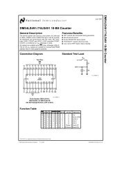
TL�F�10387–1<br />
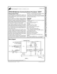
FIGURE 1-1� <strong>FDDI</strong> Chip Set Block Diagram<br />
TRI-STATE�is a registered trademark of National Semiconductor Corporation�<br />
BSI-2<strong>TM</strong>� <strong>BMAC</strong><strong>TM</strong>� PLAYERa <strong>TM</strong>� CDD<strong>TM</strong> and CRD<strong>TM</strong> are trademarks of National Semiconductor Corporation�<br />
C1995 National Semiconductor Corporation TL�F�10387<br />
RRD-B30M105�Printed in U� S� A�<br />
<strong>DP83261</strong> <strong>BMAC</strong> <strong>Device</strong> (<strong>FDDI</strong> <strong>Media</strong> <strong>Access</strong> <strong>Controller</strong>)
1�0 <strong>FDDI</strong> CHIP SET OVERVIEW<br />
2�0 ARCHITECTURAL DESCRIPTION<br />
2�1 Ring Engine<br />
2�2 Interfaces<br />
3�0 FEATURE OVERVIEW<br />
4�0 <strong>FDDI</strong> MAC FACILITIES<br />
4�1 Symbol Set<br />
4�2 Protocol Data Units<br />
4�3 Frame Counts<br />
4�4 Timers<br />
4�5 Ring Scheduling<br />
5�0 FUNCTIONAL DESCRIPTION<br />
5�1 Token Handling<br />
5�2 Servicing Transmission Requests<br />
5�3 Request Service Parameters<br />
5�4 Frame Validity Processing<br />
5�5 Frame Status Processing<br />
5�6 SMT Frame Processing<br />
5�7 MAC Frame Processing<br />
5�8 Receive Batching Support<br />
5�9 Immediate Frame Transmission<br />
5�10 Full Duplex Operation<br />
5�11 Parity Processing<br />
Table of Contents<br />
2<br />
6�0 CONTROL INFORMATION<br />
6�1 Conventions<br />
6�2 <strong>Access</strong> Rules<br />
6�3 Operation Registers<br />
6�4 Event Registers<br />
6�5 MAC Parameters<br />
6�6 Timer Thresholds<br />
6�7 Event Counters<br />
7�0 SIGNAL DESCRIPTIONS<br />
7�1 Control Interface<br />
7�2 PHY Interface<br />
7�3 MAC Indication Interface<br />
7�4 MAC Request Interface<br />
7�5 Electrical Interface<br />
7�6 Pinout Summary<br />
7�7 Pinout Diagram<br />
8�0 ELECTRICAL CHARACTERISTICS<br />
8�1 Absolute Maximum Ratings<br />
8�2 Recommended Operating Conditions<br />
8�3 DC Electrical Characteristics<br />
8�4 AC Electrical Characteristics<br />
APPENDIX A� RING ENGINE STATE MACHINES<br />
A�1 Receiver<br />
A�2 Transmitter
1�0 <strong>FDDI</strong> Chip Set Overview<br />
National Semiconductor’s DP83200 <strong>FDDI</strong> chip set consists<br />
of five components as shown in Figure 1-1� For more information<br />
on the other devices of the chip set� consult the<br />
appropriate datasheets and application notes�<br />
DP83256�56-AP�57 PLAYERa <strong>TM</strong><br />
<strong>Device</strong> Physical Layer <strong>Controller</strong><br />
The PLAYERa device implements the Physical Layer<br />
(PHY) protocol as defined by the ANSI <strong>FDDI</strong> PHY X3T9�5<br />
Standard� along with all the necessary clock recovery and<br />
clock regeneration functions�<br />
Features<br />
� Single chip <strong>FDDI</strong> Physical Layer (PHY) solution<br />
� Integrated Digital Clock Recovery Module provides enhanced<br />
tracking and greater lock acquisition range<br />
� Integrated Clock Generation Module provides all necessary<br />
clock signals for an <strong>FDDI</strong> system from an external<br />
12�5 MHz reference<br />
� Alternate PMD Interface (DP83256-AP�57) supports<br />
UTP twisted pair <strong>FDDI</strong> PMDs with no external clock recovery<br />
or clock generation functions required<br />
� No External Filter Components<br />
� Connection Management (CMT) Support (LEM� TNE�<br />
PC�React� CF�React� Auto Scrubbing)<br />
� Full on-chip configuration switch<br />
� Low Power CMOS-BIPOLAR design using a single 5V<br />
supply<br />
� Full duplex operation with through parity<br />
� Separate management interface (Control Bus)<br />
� Selectable Parity on PHY-MAC Interface and Control Bus<br />
Interface<br />
� Two levels of on-chip loopback<br />
� 4B�5B encoder�decoder<br />
� Framing logic<br />
� Elasticity Buffer� Repeat Filter and Smoother<br />
� Line state detector�generator<br />
� Supports single attach stations� dual attach stations and<br />
concentrators with no external logic<br />
� DP83256�56-AP for SAS�DAS single path stations<br />
� P83257 for SAS�DAS single�dual path stations<br />
In addition� the DP83257 contains an additional<br />
PHY�Data�request and PHY�Data�indicate port required<br />
for concentrators and dual attach stations�<br />
3<br />
<strong>DP83261</strong> <strong>BMAC</strong><strong>TM</strong> <strong>Device</strong><br />
<strong>Media</strong> <strong>Access</strong> <strong>Controller</strong><br />
The <strong>BMAC</strong> device implements the Timed Token <strong>Media</strong> <strong>Access</strong><br />
Control protocol defined by the ANSI X3T9�5 <strong>FDDI</strong><br />
MAC Standard�<br />
Features<br />
� All of the standard defined ring service options<br />
� Full duplex operation with through parity<br />
� Supports all <strong>FDDI</strong> Ring Scheduling Classes (Synchronous�<br />
Asynchronous� etc�)<br />
� Supports Individual� Group� Short� Long� and External<br />
Addressing<br />
� Generates Beacon� Claim� and Void frames internally<br />
� Extensive ring and station statistic gathering<br />
� Extensions for MAC level bridging<br />
� Separate management port that is used to configure and<br />
control operation<br />
� Multi-frame streaming interface<br />
DP83265A BSI-2 <strong>Device</strong><br />
System Interface<br />
The BSI-2 device implements an interface between the<br />
<strong>BMAC</strong> device and a host system�<br />
Features<br />
� Fully software and pin compatible with the original BSI<br />
device<br />
� Over 2 kbytes of on-chip FIFO<br />
� Operates from 12�5 MHz to 33 MHz synchronously with<br />
host system<br />
� Provides Address bit swapping capability<br />
� Reduces interface logic for SBus adapters<br />
� 32-bit wide Address�Data path with byte parity<br />
� Programmable transfer burst sizes of 4 or 8 32-bit words<br />
� Interfaces to DRAMs or directly to system bus<br />
� 2 Output and 3 Input Channels<br />
� Supports Header�Info splitting<br />
� Bridging support<br />
� Programmable Big or Little Endian alignment<br />
� Full duplex data path<br />
� Receive frame filtering services
2�0 Architectural Description<br />
The <strong>BMAC</strong> device receivers� transmits� and strips or repeats<br />
Protocol Data Units (PDUs� i�e�� Tokens and Frames) and<br />
handles the token management functions required by the<br />
timed token protocol in accordance with the <strong>FDDI</strong> MAC<br />
Standard�<br />
The <strong>BMAC</strong> device is comprised of the Ring Engine (RE) and<br />
interfaces to the Control Bus (Control Interface)� the<br />
PLAYER device (PHY Interface) and a System Interface<br />
such as the BSI device (MAC Interface) as shown in<br />
Figure 2-1�<br />
On transmission� the system interface prepares one or more<br />
frames for transmission and requests a service opportunity�<br />
Based on the requested service class and requested token<br />
type� the Ring Engine waits for a token meeting the requested<br />
criteria� When a token is captured� the Ring Engine signals<br />
the interface and soon thereafter transmission begins�<br />
After traversing the ring� frames are stripped based on the<br />
FIGURE 2-1� <strong>BMAC</strong> <strong>Device</strong> Interfaces<br />
4<br />
Source Address� Frames with a Source Address matching<br />
one of the station individual addresses are stripped by the<br />
Ring Engine� Status is available at the MAC interface for<br />
every transmitted frame�<br />
For reception� the Ring Engine sequences through the incoming<br />
byte stream� comparing received destination addresses<br />
against the station’s short or long address� The results<br />
of these comparisons are made available at the MAC<br />
interface� The System Interface then decides how to handle<br />
the frame� In the normal case� a frame with a Destination<br />
Address matching one of the station addresses is copied<br />
and passed to the system�<br />
The <strong>BMAC</strong> device utilizes a full duplex� byte-wide (symbol<br />
pair) architecture� There are two bytes of delay in the Transmit<br />
path� three bytes of delay in Receive and Repeat paths�<br />
and two bytes of delay in the Loopback path�<br />
TL�F�10387–2
2�0 Architectural Description (Continued)<br />
2�1 RING ENGINE<br />
The <strong>BMAC</strong> device is operated by the Ring Engine which is<br />
comprised of four blocks� Receiver� Transmitter� MAC Parameter<br />
RAM� and Counters�Timers as shown in Figure 2-2�<br />
2�1�1 Receiver<br />
The Receiver Block accepts data from the PLAYER device<br />
in the byte stream format (PH�Indicate)� Upon receiving the data� the Receiver Block performs the<br />
following functions�<br />
� Determines the beginning and ending of a Protocol Data<br />
Unit (PDU)<br />
� Decodes the Frame Control field to determine the PDU<br />
type (frame or token)<br />
� Compares the received Destination and Source Addresses<br />
with the internal addresses<br />
� Processes data within the frame<br />
� Calculates and checks the Frame Check Sequence at<br />
the end of the frame<br />
� Checks the Frame Status field<br />
And finally� the Receiver Block presents the data to the<br />
MAC Interface along with the appropriate control signals<br />
(MA�Indicate)� 2�1�2 Transmitter<br />
The Transmitter Block inserts frames from this station into<br />
the ring in accordance with the <strong>FDDI</strong> Timed Token MAC<br />
protocol� It also repeats frames from other stations in the<br />
ring� The Transmitter block multiplexes data from the MA� Request Interface and data from the Receiver Block� During<br />
Frame Transmission� data from the Request Interface is se-<br />
FIGURE 2-2� Ring Engine Overview Block Diagram<br />
5<br />
lected� During Frame Repeating� data from the Receiver<br />
Block is selected�<br />
During Frame Transmission� the Transmitter Block performs<br />
the following functions�<br />
� Captures a token to gain the right to transmit<br />
� Transmits one or more frames<br />
� Generates the Frame Check Sequence during transmission<br />
and appends it at the end of the frame<br />
� Generates the Frame Status field that is transmitted at<br />
the end of the frame<br />
� Issues the token at the end of frame transmission<br />
During Frame Repeating� the Transmitter Block performs<br />
the following functions�<br />
� Repeats the received frame and modifies the Frame<br />
Status field at the end of the frame as specified by the<br />
standard<br />
Whether transmitting or repeating frames� the Transmitter<br />
Block also performs the following functions�<br />
� Strips the frame(s) that are transmitted by this station<br />
� Generates Idle symbols between frames<br />
Data is presented from the Transmitter Block to the<br />
PLAYER device in the byte stream format (PH�Request)� 2�1�3 MAC Parameter RAM<br />
The MAC Parameter RAM block is a dual port RAM that<br />
contains MAC parameters such as the station’s short and<br />
long addresses� These parameters are initiallzed via the<br />
Control Interface� Both the Receiver and Transmitter Blocks<br />
may access the RAM�<br />
TL�F�10387–4
2�0 Architectural Description (Continued)<br />
The Receiver uses these parameters to compare addresses<br />
in incoming frames with its addresses stored in the Parameter<br />
RAM�<br />
The Transmitter uses the Parameter RAM for generating the<br />
Source Address for all frames (except when Source Address<br />
Transparency is enabled) and for the Destination Address<br />
and Information fields in Claim and Beacon frames�<br />
The MAC Parameter RAM block is described in greater details<br />
in Section 6�5�<br />
2�1�4 Counter�Timer<br />
The Counter�Timer block maintains all of the Counters and<br />
Timers required by the Standard�<br />
Events which occur too rapidly for software to count� such<br />
as the various Frame Counts� are included in the Event<br />
Counters� The size of the wrap around counters has been<br />
chosen to require minimal software intervention even under<br />
marginal operating conditions� Most of the Counters increment<br />
in response to events detected by the Receiver� The<br />
Counters are readable via the Control Interface�<br />
The Token Rotation and Token Holding Timers which are<br />
used to implement the Timed Token Protocol are contained<br />
within the Timer Block�<br />
The Counters and Timers are described in detail in Sections<br />
6�6 and 6�7�<br />
2�2 INTERFACES<br />
2�2�1 PHY Interface<br />
The PHY Intreface is a synchronous interface that provides<br />
an encoded byte stream to the PLAYERa device (the PHY<br />
Request byte stream)� and receives an encoded byte<br />
stream from the PLAYERa device (the PHY Indication byte<br />
stream)�<br />
The <strong>BMAC</strong> device connects to one or two PLAYERa devices<br />
via the PH�Indicate and PH�Request Interfaces�<br />
Data is transferred from the PLAYERa device to the Ring<br />
Engine via the PH�Indicate Interface� Data is transferred<br />
from the Ring Engine to the PLAYERa device via the PH� Request Interface�<br />
The 10-bit byte transferred in both directions across the<br />
PH�Indicate and PH�Request interfaces consists of one<br />
parity bit (Odd parity)� one Control bit� and 8 bits of data�<br />
The Control Bit determines if the 8 data bits are a data<br />
symbol pair or a control symbol pair�<br />
2�2�2 MAC Interface<br />
The MAC Interface provides the required information and<br />
handshakes to allow a system interface (such as the<br />
DP83265A BSI-2) to exploit the capabilities of the Ring Engine�<br />
6<br />
The MAC Interface is synchronous and is divided into separate<br />
MAC Request and MAC Indication interfaces�<br />
Data is transferred from the system interface to the Ring<br />
Engine via the MAC Request Interface� The MA�Request Interface consists of a parity bit (Odd parity) and byte-wide<br />
data along with the transmit parameters and handshake signals�<br />
The MAC Request Interface utilizes a handshake that<br />
separates token capture from data transmisson� A captured<br />
token may be held until it is no longer usable� Void frames<br />
are automatically generated to allow data interface logic as<br />
much time as it needs to prepare a transmission�<br />
Data is transferred from the Ring Engine to the system interface<br />
via the MAC Indication Interface� The MA�Indicate Interface consists of a parity bit (Odd parity) and byte-wide<br />
data along with Addressing Flags and Frame Sequencing<br />
signals� The Addressing Flags give the result of the address<br />
comparisons performed by the Ring Engine� These are used<br />
to decide whether to continue to copy or to reject frames�<br />
The MAC Indication Interface also accepts inputs to determine<br />
how to set the control indicators and increment the<br />
statistical counters based on external address comparison<br />
logic and frame copying logic� Frames may also be stripped<br />
based on external comparisons�<br />
2�2�3 Control Bus Interface<br />
The Control Interface implements the interface to the Control<br />
Bus by which to initialize� monitor and diagnose the operation<br />
of the <strong>BMAC</strong> device� The Control Interface is an<br />
8-bit asynchronous interface in order to minimize pinout and<br />
layout� All information that must be synchronized with the<br />
data stream crosses the MAC Interface�<br />
The Control bus is separated completely from the MAC and<br />
PHY Interfaces in order to allow independent operation of<br />
the processor on the Control Bus� The Control Interface<br />
provides the synchronization between the Control Bus and<br />
the Ring Engine�<br />
3�0 Feature Overview<br />
The <strong>BMAC</strong> device implements the standard <strong>FDDI</strong> MAC protocol�<br />
It also provides additional addressing� bridging� and<br />
service class functions to allow maximal flexibility in designing<br />
an <strong>FDDI</strong> station�<br />
The <strong>BMAC</strong> device offers extensive diagnostic features including<br />
a number of diagnostic counters� a dedicated interface<br />
for control and configuration� and a capability to perform<br />
Self Testing� Furthermore� the <strong>BMAC</strong> device allows the<br />
tuning of certain parameters to increase the performance of<br />
the network�
3�0 Feature Overview (Continued)<br />
3�1 <strong>FDDI</strong> MAC SUPPORT<br />
The <strong>BMAC</strong> device implements the Standard ANSI X3T9�5<br />
<strong>FDDI</strong> MAC protocol for transmitting� receiving� repeating<br />
and stripping frames� Many of the capabilities defined in<br />
MAC-2 are included in the <strong>BMAC</strong> device such as bridging<br />
end station support for setting the control indicators� and<br />
the statistic counters� The <strong>BMAC</strong> device provides all of the<br />
information necessary to implement the service primitives<br />
defined in the standard�<br />
The <strong>BMAC</strong> device also implements many of the permitted<br />
extensions to the <strong>FDDI</strong>-MAC standard as captured in the<br />
<strong>FDDI</strong> MAC-2 document� These include the extensions for<br />
MAC level bridging� Group Addressing support that can be<br />
used for SMT� reporting of additional events to aid the ring<br />
management processes and enhanced versions of the state<br />
machines�<br />
3�2 MAC ADDRESSING SUPPORT<br />
Both long (48-bit) and short (16-bit) addressing are supported<br />
simultaneously� for both Individual and Group addresses�<br />
Up to 128 contiguous programmable group addresses and<br />
up to 15 Fixed Group Addresses plus the universal�broadcast<br />
address are recognized� Limited operation with null addresses<br />
is supported� An interface to external address<br />
matching logic is provided to augment the Ring Engine’s<br />
addressing capabilities�<br />
3�3 MAC BRIDGING SUPPORT<br />
Several features are provided to aid in Bridging applications�<br />
On the receive side� external address matching logic can be<br />
used to examine the PH�Indicate byte stream to decide<br />
whether to copy a frame� how to set the control indicators<br />
and how to increment the counters�<br />
On the transmit side� transparency options are provided on<br />
the Source Address� the most significant bit of the Source<br />
Address� and the FCS�<br />
In addition� support for an alternate Void stripping mechanism<br />
provides maximal flexibility in the generation of frames�<br />
3�4 MAC SERVICE CLASS SUPPORT<br />
All of the <strong>FDDI</strong> MAC service classes are supported by the<br />
<strong>BMAC</strong> device� These include the Synchronous� Asynchronous�<br />
Restricted Asynchronous� and Immediate service<br />
classes�<br />
For Synchronous transmission� one or more frames are<br />
transmitted in accordance with the station’s synchronous<br />
bandwidth allocation�<br />
For Asynchronous transmission� one programmable asynchronous<br />
priority threshold is supported in addition to the<br />
threshold at the Negotiated Target Token Rotation time�<br />
For Restricted Asynchronous transmission� support is provided<br />
to begin� continue and end restricted dialogues�<br />
For Immediate transmissions� support is provided to send<br />
frames from either the Data� Beacon or Claim states and<br />
either ignore or respond to the received byte stream� After<br />
an immediate transmission a token may optionally be issued�<br />
3�5 DIAGNOSTIC COUNTERS<br />
The <strong>BMAC</strong> device includes a number of diagnostic counters<br />
that monitor ring and station performance�<br />
7<br />
These counters allow measurement of the following�<br />
� Number of frames transmitted and received by the station<br />
� Number of frames copied as well as frames not copied<br />
because of insufficient buffering<br />
� Frame error rate of an incoming physical connection to<br />
the MAC<br />
� Load on the ring based on the number of tokens received<br />
and the ring latency<br />
� Ring latency<br />
� Lost frames<br />
The size of these counters has been selected to keep the<br />
frequency of overflow small� even under worst case operating<br />
conditions�<br />
3�6 MANAGEMENT SERVICES<br />
The <strong>BMAC</strong> device provides management services to the<br />
Host System via the Control Bus Interface� This interface<br />
allows access to internal registers to control and configure<br />
the <strong>BMAC</strong> device�<br />
3�7 RING PARAMETER TUNING<br />
The <strong>BMAC</strong> device includes settable parameters to allow<br />
tuning of the network to increase performance over a large<br />
range of network sizes�<br />
The <strong>BMAC</strong> device supports systems of two stations with<br />
little cable between them to ring configurations much larger<br />
than the 1000 physical attachments and�or 200 km distance<br />
that are specified as the default values in the standard�<br />
The <strong>BMAC</strong> device also handles frames larger than the 4500<br />
byte default maximum frame size as specified in the Standard�<br />
3�8 MULTI-FRAME STREAMING INTERFACE<br />
The <strong>BMAC</strong> device provides an interface to support a multiframe<br />
streaming interface� Multiple frames can be transmitted<br />
after a token is captured within the limits of the token<br />
timer thresholds�<br />
3�9 GENERATES BEACON� CLAIM�<br />
AND VOID FRAMES INTERNALLY<br />
For purposes of transient token and ring recovery� no processor<br />
intervention is required� The <strong>BMAC</strong> device automatically<br />
generates the appropriate MAC frames�<br />
3�10 SELF TESTING<br />
Because the <strong>BMAC</strong> device is full duplex� loopback testing is<br />
possible before entering the ring and during normal ring operation�<br />
There are several posible loopback paths�<br />
� internal to the <strong>BMAC</strong> device<br />
� through the PLAYER device(s) using the PLAYER device<br />
configuration switch<br />
� through the CRD device�<br />
These paths allow error isolation down to the device level�<br />
The <strong>BMAC</strong> device also supports through parity�
4�0 <strong>FDDI</strong> MAC Facilities<br />
4�1 SYMBOL SET<br />
The Ring Engine recognizes and generates a set of symbols�<br />
These symbols are used to convey Line States (such<br />
as the Idle Line State)� Control Sequences (such as the<br />
Starting and Ending Delimiters) and Data�<br />
Additional information regarding the symbol set can be<br />
found in the <strong>FDDI</strong> PHY Standard�<br />
The Ring Engine expects that the Starting Delimiter will always<br />
be conveyed on an even symbol pair boundary� Following<br />
the starting delimiter� data symbols should always<br />
come in matched pairs� Similarly the Ending Delimiter<br />
should always come in one or more matched symbol pairs�<br />
The symbol pairs conveyed at the PHY Interface are shown<br />
in Table 4-1�<br />
4�2 PROTOCOL DATA UNITS<br />
The Ring Engine recognizes and generates two types of<br />
Protocol Data Units (PDUs)� Tokens and Frames�<br />
The Token is used to control access to the ring� Only the<br />
station that has captured the token has the right to transmit<br />
new information� The format of a token is shown in Figure<br />
4-1�<br />
SFS EFS<br />
PA SD FC ED<br />
FIGURE 4-1� Token Format<br />
Frames are used to pass information between stations� The<br />
format of a frame is shown in Figure 4-2 with the field definitions<br />
in Table 4-2�<br />
SFS Protected by PCS EFS<br />
PA SD FC DA SA INFO FCS ED FS<br />
FIGURE 4-2� Frame Format<br />
TABLE 4-1� Symbol Pair Set<br />
Type Symbols<br />
Starting Delimiter JK<br />
Ending Delimiter TT or TR or TS or nT<br />
Frame Status RR or RS or SR or SS<br />
Idle ll or nl<br />
Data Pair nn<br />
Note � n represents any data symbol (0–F)�<br />
Symbol pairs others than the defined symbols are treated as code violations�<br />
Section 7�2 has additional information on the symbol pairs generated and interpreted by the Ring Engine�<br />
TABLE 4-2� PDU Fields<br />
Name Description Size<br />
SFS Start of Frame Sequence<br />
PA Preamble 8 or More Idle Symbol Pairs<br />
SD Starting Delimiter JK Symbol Pair<br />
FC Frame Control Field 1 Data Symbol Pair<br />
DA Destination Address 2 or 6 Symbol Pairs<br />
SA Source Address 2 or 6 Symbol Pairs<br />
INFO Information Field<br />
FCS Frame Check Sequence 4 Symbol Pairs<br />
EFS End of Frame Sequence<br />
ED Ending Delimiter At Least 1T Symbol for Frames�<br />
At Least 2T Symbols for Tokens<br />
FS Frame Status 3 or More R or S Symbols<br />
8
4�0 <strong>FDDI</strong> MAC Facilities (Continued)<br />
4�2�1 PDU Fields<br />
Start of Frame Sequence<br />
The Start of Frame Sequence (SFS) consists of the Preamble<br />
(PA) followed by the Starting Delimiter (SD)�<br />
The Preamble is a sequence of zero or more Idle symbols<br />
that is used to separate the PDUs� The Ring Engine Receiver<br />
can process and repeat a frame or token with no preamble�<br />
The Ring Engine Transmitter generates frames with at<br />
least 8 bytes of preamble� The Ring Engine Transmitter also<br />
guarantees that valid <strong>FDDI</strong> frames will never be transmitted<br />
with more than 40 bytes of preamble�<br />
The Starting Delimiter is used to indicate the start of a new<br />
PDU� The Starting Delimiter is the JK symbol pair�<br />
The Ring Engine expects the Starting Delimiter to be conveyed<br />
across the PH�Indication Interface as a single byte�<br />
Similarly� the Ring Engine only generates Starting Delimiters<br />
aligned to the byte boundary�<br />
Frame Control<br />
The Frame Control (FC) field is used to discriminate PDUs�<br />
For tokens� the FC field identifies Restricted and Non-restricted<br />
tokens� For frames� the FC field identifies the frame<br />
types and format and how the frame is to be processed�<br />
The one byte FC field is formatted as shown in Figure 4-3�<br />
C L FF r ZZZ<br />
FIGURE 4-3� Frame Control Field<br />
The C (Class) bit specifies the MAC Service Class as Asynchronous<br />
(C e 0) or Synchronous (C e 1)�<br />
The L (Length) bit specifies the length of the MAC Address<br />
as Short (L e 0) or Long (L e 1)� A Short Address is a 16bit<br />
address� A Long Address is a 48-bit address�<br />
The FF (Format) bits specify the PDU types as shown in<br />
Table 4-3�<br />
The r (Reserved) bit is currently not specified and should<br />
always be transmitted as Zero (Exception� SMT NSA<br />
Frames)�<br />
The ZZZ (Control) bits are used in conjunction with the C<br />
and FF bits to specify the type of PDUs� These bits may be<br />
used to affect protocol processing criteria such as the Priority�<br />
Protocol Class� Status Handling� etc�<br />
TABLE 4-3� Frame Control Format Bits<br />
FC�FF PDU Types<br />
0 0 SMT�MAC<br />
0 1 LLC<br />
1 0 Reserved for Implementer<br />
1 1 Reserved for Future Standardization<br />
When the Frame Control Format bits (FC�FF) indicate a<br />
SMT or MAC PDU� the frame type is identified as shown in<br />
Table 4-4�<br />
9<br />
TABLE 4-4� MAC�SMT Frames Types<br />
CLFF rZZZ PDU Type<br />
1000 0000 Non-Restricted Token<br />
1100 0000 Restricted Token<br />
0L00 0000 Void Frame<br />
0L00 0001 to<br />
1110<br />
SMT Frame<br />
0L00 1111 SMT Next Station<br />
Addressing Frame<br />
1L00 0001 Other MAC Frame<br />
1L00 0010 MAC Beacon Frame<br />
1L00 0011 MAC Claim Frame<br />
1L00 0100 to<br />
1111<br />
Other MAC Frame<br />
Destination Address<br />
The Destination Address (DA) field is used to specify the<br />
station(s) that should receive and process the frame�<br />
The DA can be an Individual or Group address� This is determined<br />
by the Most Significant Bit of the DA (DA�IG)�<br />
When DA�IG is 0 the DA is an Individual Address� when<br />
DA�IG is 1 the DA is a Group Address� The Broadcast�Universal<br />
address is a Group Address�<br />
The DA field can be a Long or Short Address� This is determined<br />
by the L bit in the FC field (FC�L)� If FC�L is 1� the DA<br />
is a 48-bit Long Address� If FC�L is 0� the DA is a 16-bit<br />
Short Address�<br />
The Ring Engine maintains both a 16-bit Individual Address�<br />
My Short Address (MSA) and a 48-bit Individual Address�<br />
My Long Address (MLA)�<br />
On the receive side� if DA�IG is 0 the incoming DA is compared<br />
with MLA (if FC�L e 1) or MSA (if FC�L e 0)� If the<br />
received DA matches MLA or MSA the frame is intended for<br />
this station and the address recognized flag (A�Flag) is set�<br />
If DA�IG is 1� the DA is a Group Address and is compared<br />
with the set of Group Addresses recognized by the Ring<br />
Engine� If a match occurs the address recognized flag<br />
(A�Flag) is set� The A�Flag is used by system interface<br />
logic as part of the criteria (with FC�L� DA�IG and<br />
M�Flag) to determine whether or not to copy the frame� If<br />
the A�flag is set� the system interface will normally attempt<br />
to copy the frame�<br />
On the transmit side� the DA is provided by the system interface<br />
logic as part of the data stream� The length of the<br />
address to be transmitted is determined by the L bit of the<br />
FC field� (The FC field is also passed in the data stream�)<br />
The Destination Address can be an Individual� Group� or<br />
Broadcast Address�<br />
Source Address<br />
The Source Address (SA) field is used to specify the address<br />
of the station that originally transmitted the frame�
4�0 <strong>FDDI</strong> MAC Facilities (Continued)<br />
The Source Address has the same length as the Destination<br />
Address (i�e�� if the DA is a 16-bit Address� the SA is a 16-bit<br />
Address� if the DA is a 48-bit Address� the SA is a 48-bit<br />
Address)�<br />
On the receive side� the incoming SA is compared with either<br />
MSA or MLA� If a match occurs between the incoming<br />
SA and this station’s MLA or MSA� the M�Flag is set� This<br />
flag is used to indicate that the frame is recognized as having<br />
been transmitted by this station and is stripped� The<br />
most significant bit of the SA (SA�IG) is not evaluated in the<br />
comparison�<br />
On the transmit side� the station’s individual address is<br />
transmitted as the SA� Since the SA field is normally used<br />
for stripping frames from the ring� the SA stored by the Ring<br />
Engine normally replaces the SA from the data stream� The<br />
length of the address to be transmitted is determined by the<br />
L bit of the FC field� (The FC field is passed in the data<br />
stream�) The most significant bit of the SA (SA�IG) is normally<br />
transmitted as 0� independent of the value passed<br />
through the data stream�<br />
As a transmission option� the SA may also be transmitted<br />
transparently from the data stream� When the SA Transparency<br />
option is used� an alternate stripping mechanism is<br />
necessary to remove these frames from the ring� (The Ring<br />
Engine provides a Void Stripping Option� See Section<br />
7�4�2�4 for futher information�)<br />
As a separate and independent transmission option� the<br />
MSB of the SA may also be transmitted transparently from<br />
the data stream� This is useful for end stations participating<br />
in the Source Routing protocol�<br />
Information<br />
The Information field (Info) contains the Service Data Unit<br />
(SDU)� A SDU is the unit of data transfer between peer users<br />
of the MAC data service (SMT� LLC� etc)� There is no<br />
INFO field in a Token�<br />
The INFO field contains zero or more bytes�<br />
On the receive side� the INFO field is checked to ensure<br />
that it has at least the minimum length for the frame type<br />
and contains an even number of symbols� as required by the<br />
Standard�<br />
The first 4 bytes of the INFO field of MAC frames (e�g�� MAC<br />
Beacon or MAC Claim) are stored in an internal register and<br />
compared against the INFO field of the next MAC frame� If<br />
the data of the two frames match� the SameInfo signal is<br />
generated� This signal may be used to copy MAC frames<br />
only when new information is present�<br />
On the transmit side� the Ring Engine does not limit the<br />
maximum size of the INFO field� but it does insure that<br />
frames are transmitted with a valid DA and SA�<br />
Frame Check Sequence<br />
The Frame Check Sequence (FCS) is a 32-bit Cyclic Redundancy<br />
Check that is used to check for data corruption in<br />
frames� There is no FCS field in a Token�<br />
On the receive side� the Ring Engine checks the FCS to<br />
determine whether the frame is valid or corrupted�<br />
On the transmit side� the FCS field is appended to the end<br />
of the INFO field� As a transmission option� appending the<br />
FCS to the frame can be inhibited (FCS Transparency)�<br />
10<br />
End of Frame Sequence<br />
The End of Frame Sequence (EFS) always begins with a T<br />
symbol and should always contain an even number of symbols�<br />
For Tokens an additional T symbol is added� For<br />
frames the Ending Delimiter (ED) is followed by one or more<br />
Frame Status Indicators (FS)�<br />
The Frame Status (FS) field is used to indicate the status of<br />
the frame� The FS field consists of three Indicators� Error<br />
Detected (E)� Address Recognized (A)� and Frame Copied<br />
(C)� These Indicators are created and modified as specified<br />
in the Standard�<br />
For frames transmitted by the Ring Engine� the E� A and C<br />
Indicators are appended to all frames and are transmitted<br />
as R symbols� No provisions are made to generate additional<br />
trailing control indicators�<br />
For frames repeated by the Ring Engine� the E� A and C<br />
Indicators are handled as specified in the Standard� Additional<br />
trailing control indicators are repeated unmodified<br />
provided they are properly aligned� See Section 5�5 for details<br />
on Frame Status Processing�<br />
4�2�2 Token Formats<br />
The Ring Engine supports non-restricted and restricted Tokens�<br />
See Figures 4-4 and 4-5�<br />
SFS FC EFS<br />
SD 80 ED<br />
FIGURE 4-4� Non-Restricted Token Format<br />
SFS FC ED<br />
SD C0 ED<br />
FIGURE 4-5� Restricted Token Format<br />
Non-Restricted<br />
A non-restricted token is used for synchronous and non-restricted<br />
asynchronous transmissions�<br />
Each time the non-restricted token arrives� a station is permitted<br />
to transmit one or more frames in accordance with its<br />
synchronous bandwidth allocation regardless of the status<br />
of the token (late or early)�<br />
Asynchronous transmissions occur only if the token is early<br />
(usable token) and the Token Holding Timer has not<br />
reached the selected threshold�<br />
Restricted<br />
A restricted token is used for synchronous and restricted<br />
asynchronous transmissions only�<br />
A station which initiates the restricted dialogue captures a<br />
non-restricted token and releases a restricted token� Stations<br />
that participate in the restricted dialogue are allowed<br />
to capture the restricted token� A station ends the restricted<br />
dialogue by capturing the restricted token and releasing a<br />
non-restricted token�<br />
4�2�3 Frame Formats<br />
The Ring Engine supports all of the frame formats permitted<br />
by the <strong>FDDI</strong> standard� All frame types may be created external<br />
to the <strong>BMAC</strong> device and be passed through the MAC<br />
Request Interface to the Ring� The <strong>BMAC</strong> device also has<br />
the ability to generate Void� Beacon and Claim frames internally�
4�0 <strong>FDDI</strong> MAC Facilities (Continued)<br />
Frames Generated Externally<br />
The Ring Engine transmits frames passed to it from the System<br />
Interface� The data portion of the frame is created by<br />
the System Interface� This begins with the FC field and ends<br />
with the last byte of the INFO field� The FC field is passed<br />
transparently to the ring� The length bit in the FC field is<br />
used to determine the length of the transmitted addresses�<br />
The data is passed as a byte stream across the MAC Request<br />
Interface as shown in Table 4-5�<br />
Before the frame is transmitted� the Ring Engine inserts the<br />
Start of Frame Sequence with at least 8 bytes of Preamble<br />
but no more than 40 bytes of Preamble� The starting delimiter<br />
is transmitted as a JK symbol pair� The Source Address<br />
is normally transmitted by the Ring Engine since it uses the<br />
Source Address to strip the frame from the ring� This can be<br />
overridden by using the Source Address transparency capability�<br />
Similarly� the Frame Check Sequence (4 bytes) is normally<br />
transmitted by the Ring Engine� This can be overridden<br />
with the FCS transparency capability� With FCS transparency�<br />
the FCS is transmitted from the data stream� The<br />
End of Frame Sequence is always transmitted by the Ring<br />
Engine as TR RR�<br />
Frames transmitted by the Ring Engine must have a valid<br />
DA and SA field� If the end of a frame is reached before a<br />
valid length is transmitted� the frame will be aborted and a<br />
Void frame will be transmitted�<br />
TABLE 4-5� Frame Formats<br />
Field Size MA�Request PH�Request PA t8� s40 Idle Pairs<br />
SD 1 JK<br />
FC 1 FC FC<br />
DA 2 or 6 DA DA<br />
SA 2 or 6 SA MSA� MLA�<br />
or SA<br />
INFO t 0 INFO INFO<br />
FCS 4 if Present FCS FCS<br />
ED 1 TR<br />
FS 1 RR<br />
Frames Generated by the Ring Engine<br />
The Ring Engine generates and detects several frames in<br />
order to attain and maintain an operational ring�<br />
Void Frames<br />
Void frames are used during normal operation� The Ring<br />
Engine generates two types of void frames� regular Void<br />
frames and My�Void frames� See Table 4-6�<br />
If short addressing is enabled� Void frames with the short<br />
address are transmitted� otherwise Void frames with the<br />
long address are transmitted�<br />
Void frames are transmitted in order to reset the Valid<br />
Transmission timers (TVX) in other stations in order to eliminate<br />
an unnecessary entry to the Claim state� Stations are<br />
not required to copy Void frames� Void frames are transmitted<br />
by the Ring Engine in two situations�<br />
1� While holding a token when no data is ready to be transmitted�<br />
2� After a frame transmission is aborted�<br />
My�Void frames are transmitted by the Ring Engine in<br />
three situations�<br />
1� After a request to measure the Ring Latency has been<br />
made when the next early token is captured�<br />
2� After this station wins the Claim Process before the token<br />
is issued�<br />
3� After a frame has been transmitted with the STRIP option<br />
before the token for that service opportunity is issued�<br />
Void frames are also detected by the Ring Engine� A Void<br />
frame with a Source Address other than MSA or MLA is<br />
considered an Other�Void frame�<br />
Claim Frames<br />
Claim frames are generated continuously with minimum preamble<br />
while the Ring Engine is in the Transmit Claim state�<br />
The format of Claim frames generated by the Ring Engine is<br />
shown in Table 4-7� When long addressing is enabled�<br />
frames with the long address are transmitted� otherwise<br />
frames with the short address are transmitted�<br />
The Ring Engine detects reception of valid Claim frames� A<br />
comparison is performed between the (first) four bytes of<br />
the received INFO field and TREQ in order to distinguish<br />
Higher�Claim� Lower�Claim� and My�Claim� Details are<br />
given in Appendix A�<br />
TABLE 4-6� Void Frames<br />
Type Enable Size SFS FC DA SA FCS EFS<br />
Void ESA Short PA SD 00 Null MSA FCS TRRR<br />
Void Not ESA Long PA SD 40 Null MLA FCS TRRR<br />
My�Void ESA Short PA SD 00 MSA MSA FCS TRRR<br />
My � Void Not ESA Long PA SD 40 MLA MLA FCS TRRR<br />
TABLE 4-7� Claim Frames<br />
Type Enable Size SFS FC DA SA INFO FCS EFS<br />
My � Claim Not ELA Short PA SD 83 MSA MSA TREQ FCS TRRR<br />
My � Claim ELA Long PA SD C3 MLA MLA TREQ FCS TRRR<br />
11
4�0 <strong>FDDI</strong> MAC Facilities (Continued)<br />
Beacon Frames<br />
Beacon frames are transmitted continuously with minimum<br />
preamble when the Ring Engine is in the Transmit Beacon<br />
state� The format of Beacon frames generated by the Ring<br />
Engine is shown in Table 4-8� When long addressing is enabled�<br />
frames with the long address are transmitted� otherwise<br />
frames with the short address are transmitted�<br />
When the Transmit Beacon State is entered from the Transmit<br />
Claim State the first byte of the 4 byte TBT Field is<br />
transmitted as Zero�<br />
Beacon frames that require alternative formats such as Directed<br />
Beacons must be generated externally�<br />
The Ring Engine detects reception of valid Beacon frames<br />
and distinguishes between Beacon frames transmitted by<br />
this MAC (My�Beacon) and Beacon frames transmitted by<br />
other stations (Other�Beacon)� Details are given in Appendix<br />
A�<br />
4�3 FRAME COUNTS<br />
To aid in fault isolation and to enhance the management<br />
capabilities of a ring� the Ring Engine maintains several<br />
frame counts� The Error and Isolated frame counts increment<br />
when a frame is received with one or more errors that<br />
were previously undetected� The Ring Engine then corrects<br />
the error such that a downstream station will not increment<br />
its count�<br />
The size of the counters has been chosen such that minimal<br />
software intervention is required� even under marginal operating<br />
conditions�<br />
The following counts are maintained by the Ring Engine�<br />
FRCT Frame Received<br />
EICT Error Isolated<br />
LFCT Lost Frame<br />
FCCT Frames Copied<br />
FNCT Frames Not Copied<br />
FTCT Frames Transmitted<br />
4�3�1 Frame Received Count<br />
The Frame Received Count (FRCT) is specified in the <strong>FDDI</strong><br />
MAC Standard� and is the count of all complete frames received�<br />
This count includes frames stripped by this station�<br />
4�3�2 Error Isolated Count<br />
The Error Isolated Count (EICT) is specified in the <strong>FDDI</strong><br />
MAC Standard� and is the count of error frames detected by<br />
this station and no previous station� It increments when�<br />
1� An FCS error is detected and the received Error Indicator<br />
(Er) is not equal to S�<br />
2� A frame of invalid length (i�e�� off boundary T) is received<br />
and Er is not equal to S�<br />
3� Er is not R or S�<br />
TABLE 4-8� Beacon Frames<br />
4�3�3 Lost Frame Count<br />
The Lost Frame Count (LFCT) is specified in the <strong>FDDI</strong> MAC<br />
Standard� and is the count of all instances where a format<br />
error is detected in a frame or token such that the credibility<br />
of PDU reception is placed in doubt� The Lost Frame Count<br />
is incremented when any symbol other than data or Idle<br />
symbols are received between the Starting and Ending Delimiters<br />
of a PDU (this includes parity errors)�<br />
4�3�4 Frame Copied Count<br />
The Frames Copied Count (FCCT) is specified in the <strong>FDDI</strong><br />
MAC-2 Standard� and is the count of the number of frames<br />
copied by this station� The count is incremented when an<br />
internal or external match occurs (when Option�EMIND is<br />
enabled) on the Destination Address� no errors were detected<br />
in the frame and the frame was successfully copied<br />
(VCOPY e 1)� This can be used to accumulate station performance<br />
statistics� Frames copied promiscuously� MAC<br />
frames� Void frames and NSA frames received with the A<br />
indicator set are not included in this count�<br />
4�3�5 Frames Not Copied Count<br />
The Frames Not Copied Count (FNCT) is specified in the<br />
<strong>FDDI</strong> MAC-2 Standard� and is the count of frames intended<br />
for this station that were not successfully copied by this<br />
station� The count is incremented when an internal or external<br />
(when Option�EMIND is enabled) Destination Address<br />
match occurs� no errors were detected in the frame� and the<br />
frame was not successfully copied (VCOPY e 0)� This<br />
count is an indication of insufficient buffering or frame processing<br />
capability for frames addressed to the station� MAC<br />
frames� Void frames and NSA frames received with the A<br />
indicator set are not included in this count�<br />
4�3�6 Frames Transmitted Count<br />
The Frames Transmitted Count (FTCT) is specified in the<br />
<strong>FDDI</strong> MAC-2 Standard� and is incremented every time a<br />
complete frame is transmitted from the MAC Request Interface�<br />
The count is provided as an aid to accumulate station<br />
performance statistics� Void and MAC frames generated by<br />
the Ring Engine are not included in the count�<br />
4�4 TIMERS<br />
4�4�1 Token Rotation Timer<br />
The Token Rotation Timer (TRT) times token rotations from<br />
arrival to arrival� TRT is used to control ring scheduling during<br />
normal operation and to detect and recover from serious<br />
ring error situations�<br />
TRT is loaded with the maximum token rotation time� <strong>TM</strong>AX�<br />
when the ring is not operational� TRT is loaded with the<br />
negotiated Target Token Rotation Time� TNEG� when the<br />
ring is operational�<br />
Type Enable Size SFS FC DA SA INFO FCS EFS<br />
My � Beacon Not ELA Short PA SD 82 Null MSA TBT FCS TRRR<br />
My � Beacon ELA Long PA SD C2 Null MLA TBT FCS TRRR<br />
12
4�0 <strong>FDDI</strong> MAC Facilities (Continued)<br />
4�4�2 Token Holding Timer<br />
The Token Holding timer (THT) is used to limit the amount<br />
of ring bandwidth used by a station for asynchronous traffic<br />
once the token is captured� THT is used to determine if the<br />
captured token is (still) usable for asynchronous transmission�<br />
A token is usable for asynchronous traffic if THT has<br />
not reached the selected threshold� Two asynchronous<br />
thresholds are supported� one that is fixed at the Negotiated<br />
Target Token Rotation Time (TNEG)� and one that is programmable<br />
at one of 16 Asynchronous Priority Thresholds�<br />
Requests to transmit frames at one of the priority thresholds<br />
are serviced when the Token Holding Timer (THT) has not<br />
reached the selected threshold�<br />
4�4�3 Late Count<br />
The Late Count (LTCT) is implemented differently than suggested<br />
by the Standard� but provides similar information�<br />
The function of the Late Count is divided beween the Late� Flag that is equivalent to the standard Late Count with a<br />
non-zero value and a separate counter� Late Flag is maintained<br />
by the Ring Engine to indicate if it is possible to send<br />
asynchronous traffic� When the ring is operational� Late<br />
Count indicates the time it took the ring to recover the last<br />
time the ring went non-operational� When the ring is non-operational�<br />
Late Count indicates the time it has taken (so far)<br />
to recover the ring�<br />
The Late Count is incremented every time TRT expires<br />
while the ring is non-operational and Late�Flag is set (once<br />
every <strong>TM</strong>AX)�<br />
The Late Count is provided to assist Station Management�<br />
SMT� in the isolation of serious ring errors� In many situations<br />
the ring will recover very quickly and late count will be<br />
of marginal utility� However in the case of serious ring errors�<br />
it is helpful for SMT to know how long it has been since<br />
the ring went non-operational (with <strong>TM</strong>AX resolution) in order<br />
to determine if it is necessary to invoke recovery procedures�<br />
When the ring goes no operational there is no way to<br />
know how long it will stay non-operational� therefore a timer<br />
is necessary� If the Late Count were not provided� SMT<br />
would be forced to start a timer every time the ring goes<br />
non-operational even though it may seldom be used� By using<br />
the provided Late Count� an SMT implementation may<br />
be able to alleviate this additional overhead�<br />
4�4�4 Valid Transmission Timer<br />
The Valid Transmission Timer (TVX) is reset every time a<br />
valid PDU is received� TVX is used to increase the responsiveness<br />
of the ring to errors� Expiration of the TVX indicates<br />
that no PDU has been received within the timeout<br />
period and causes the Transmitter to invoke the recovery<br />
Claim Process�<br />
4�4�5 Token Received Count<br />
The Token Received Count (TKCT) is incremented every<br />
time a valid token arrives� The Token Count can be used<br />
with the Ring Latency Count to calculate the average network<br />
load over a period of time� The frequency of token<br />
arrival is inversely related to the network load�<br />
4�4�6 Ring Latency Count<br />
The Ring Latency Count (RLCT) is a measurement of time<br />
for PDUs to propagate around the ring� This counter contains<br />
the last measured ring latency whenever the Ring Latency<br />
Valid bit of the Token Event Register (TELR�RLVLD)<br />
is one�<br />
13<br />
The Latency Counter increments every 16 byte times<br />
(1�28 ms) and is used to measure ring latencies up to<br />
1�3421772 seconds directly with an accuracy of 1�2 ms� No<br />
overflow or increment event is provided with this counter�<br />
4�5 RING SCHEDULING<br />
<strong>FDDI</strong> uses a timed token protocol to schedule the use of the<br />
ring� The protocol measures load on the network by timing<br />
the rotation of the token� The longer the token rotation time<br />
the greater the instantaneous load on the network� By limiting<br />
the transmission of data when the token rotation time<br />
exceeds a target rotation time� a maximum average token<br />
rotation time is realized� The protocol is used to provide<br />
different classes of service�<br />
Multiple classes of service can be accommodated by setting<br />
different target token rotation times for each class of service�<br />
The Ring Engine supports Synchronous� Non-Restricted<br />
Asynchronous� Restricted Asynchronous� and Immediate<br />
service classes� The Immediate service class is supported<br />
when the ring is non-operational� the other classes are supported<br />
when the ring is operational�<br />
4�5�1 Synchronous Service Class<br />
The Synchronous service class may be used to guarantee a<br />
maximum response time (2 times TTRT)� minimum bandwidth�<br />
or both�<br />
Each time the token arrives� a station is permitted to transmit<br />
one or more frames in accordance with its synchronous<br />
bandwidth allocation regardless of the status of the token<br />
(late or early� Restricted or Non-Restricted)�<br />
Since the Ring Engine does not provide a mechanism for<br />
monitoring a station’s synchronous bandwidth utilization�<br />
the user must insure that no synchronous request requires<br />
more than the allocated bandwidth�<br />
To help ensure that synchronous bandwidth is properly allocated<br />
after ring configuration� synchronous requests are not<br />
serviced after a Beacon frame is received� After a major<br />
reconfiguration has occurred� management software must<br />
intervene to verify or modify the current synchronous bandwidth<br />
allocation�<br />
4�5�2 Non-Restricted Asynchronous Service Class<br />
The Non-Restricted Asynchronous service class is typically<br />
used with interactive and background traffic� Non-restricted<br />
Asynchronous requests are serviced only if the token is early<br />
and the Token Holding Timer has not reached the selected<br />
threshold�<br />
Asynchronous service is available at two priority thresholds�<br />
the Negotiated Target Token Rotation Time plus one programmable<br />
threshold� Management software may use the<br />
priority thresholds to discriminate additional classes of traffic<br />
based on current loading characteristics of the ring� The<br />
priority thresholds may be determined using the current<br />
TTRT and the Ring Latency� In this case� application software<br />
is only concerned with the priority level of a request�<br />
As an option� Asynchronous Requests may be serviced with<br />
THT disabled� This is useful when it is necessary to guarantee<br />
that a multi-frame request will be serviced on a single<br />
token opportunity� Because of the possibility of causing late<br />
tokens� this capability should be used with caution� and<br />
should only be allowed when absolutely necessary�
4�0 <strong>FDDI</strong> MAC Facilities (Continued)<br />
4�5�3 Restricted Asynchronous Service Class<br />
The Restricted Asynchronous service class is useful for<br />
large transfers requiring all of the available Asynchronous<br />
bandwidth� The Restricted Token service is useful for large<br />
transfers requiring all of the available (remaining) asynchronous<br />
bandwidth�<br />
The Restricted Token service may also be used for operations<br />
requiring instantaneous allocation of the remaining<br />
synchronous bandwidth when Restricted Requests are<br />
serviced with THT disabled� This is useful when it is necessary<br />
to guarantee atomicity� i�e�� that a multi-frame request<br />
will be serviced on a single token opportunity�<br />
A Restricted dialogue consists of three phases�<br />
1� Initiation of a Restricted dialogue�<br />
� Capture a Non-Restricted Token<br />
� Transmit zero or more frames to establish a Restricted<br />
dialogue with other stations<br />
� Issue a Restricted Token to allow other stations in the<br />
dialogue to transmit frames<br />
2� Continuation of a Restricted dialogue�<br />
� Capture a Restricted Token<br />
� Transmit zero or more frames to continue the Restricted<br />
dialogue<br />
� Issue a Restricted Token to allow other stations in the<br />
dialogue to transmit frames<br />
3� Termination of a Restricted dialogue�<br />
� Capture a Restricted Token<br />
� Transmit zero or more frames to continue the Restricted<br />
dialogue<br />
� Issue a Non-restricted Token to return to the Non-restricted<br />
service class<br />
Initiation of a Restricted dialogue will prevent all Non-restricted<br />
Asynchronous traffic throughout the ring for the duration<br />
of the dialogue� but will not affect Synchronous traffic�<br />
To ensure that the Restricted traffic is operating properly� it<br />
is possible to monitor the use of Restricted Tokens on the<br />
ring� When a Restricted Token is received� the event is<br />
latched and under program control may generate an interrupt�<br />
In addition� a request to begin a Restricted dialogue<br />
will only be honored if both the previous transmitted Token<br />
and the current received Token were Non-restricted tokens�<br />
This is to ensure that the upper bound on the presence of a<br />
Restricted dialogue in the ring is limited to a single dialogue�<br />
As suggested by the MAC-2 Draft standard� to help ensure<br />
that only one Restricted dialogue will be in progress at any<br />
given time� Restricted Requests are not serviced after a<br />
MAC frame is received until Restricted Requests are explicitly<br />
enabled by management software� Since the Claim Process<br />
results in the generation of a Non-restricted Token�<br />
this prevents stations from initiating another restricted dialogue<br />
without the intervention of management software�<br />
4�5�4 Immediate Service Class<br />
The Immediate service class facilitates several non-standard<br />
applications and is useful in ring failure recovery (e�g��<br />
Transmission of Directed Beacons)� Certain ring failures<br />
may cause the ring to be unusable for normal traffic� until<br />
the failure is remedied�<br />
14<br />
Immediate requests are only serviced when the ring is nonoperational�<br />
Immediate requests may be serviced from the<br />
Transmitter Data� Claim� and Beacon states Options are<br />
available to force the Ring Engine to enter the Claim or<br />
Beacon state� to prohibit it from entering the Claim state� or<br />
to remain in the Claim state when receiving My�Claim� On the completion of an Immediate request� a Token (Nonrestricted<br />
or Restricted) may optionally be issued� Immediate<br />
requests may also be used in non-standard applications<br />
such as a full duplex point to point link�<br />
5�0 Functional Description<br />
5�1 TOKEN HANDLING<br />
5�1�1 Token Timing Logic<br />
The <strong>FDDI</strong> Ring operates based on the Timed Token Rotation<br />
protocol where all stations on the ring negotiate on the<br />
maximum time that the stations have to wait before being<br />
able to transmit frames� This value is termed the Negotiated<br />
Target Token Rotation Time (TTRT)� The TTRT value is<br />
stored in the TNEG Register�<br />
Stations negotiate for TTRT based on their TREQ that is<br />
assigned to them upon initialization�<br />
Each station keeps track of the token arrival by setting the<br />
Token Rotation Timer (TRT) to the TTRT value� If the token<br />
is not received within TTRT (the token is late)� the event is<br />
recorded by setting the Late�Flag� If the token is not received<br />
within twice TTRT (TRT expires and Late�Flag is<br />
set)� there is a potential problem in the ring and the recovery<br />
process is invoked�<br />
Furthermore� the Token Holding Timer (THT) is used to limit<br />
the amount of ring bandwidth used by a station for Asynchronous<br />
traffic once the token is captured� Asynchronous<br />
traffic is prioritized based on the Late�Flag which denotes<br />
a threshold at TTRT and an additional Asynchronous Priority<br />
Threshold (THSH)� The Asynchronous Threshold comparison<br />
(Apri 1) is pipelined� so a threshold crossing may not<br />
be detected immediately� however� the possible error is a<br />
fraction of the precision of the threshold values�<br />
The Token Timing Logic consists of two Timers� TRT and<br />
THT� in addition to the <strong>TM</strong>AX and TNEG values loaded into<br />
these counters (See Figure 5-1 )�<br />
The Timers are implemented as count-up counters that increment<br />
every 80 ns� The Timers are reset by loading TNEG<br />
or <strong>TM</strong>AX into the counters where TNEG and <strong>TM</strong>AX are unsigned<br />
twos complement numbers� This allows a Carry flag<br />
to denote timer expiration�<br />
On an early token arrival (Late�Flag is not set)� TRT is<br />
loaded with TNEG and counts up� On a late token arrival<br />
(Late�Flag is set)� Late�Flag is cleared and TRT continues<br />
to count� When TRT expires and Late�Flag is not set�<br />
Late�Flag is set and TRT is loaded with TNEG�<br />
THT follows the value of TRT until a token is captured�<br />
When a token is captured� TRT may be reloaded with TNEG<br />
while THT continues to count from its previous value (THT<br />
does not wrap around)� THT increments when enabled� THT<br />
is disabled during synchronous transmission and a special<br />
class of asynchronous transmission� THT is used to determine<br />
if the token is usable for asynchronous requests�
5�0 Functional Description (Continued)<br />
If TRT expires while Late�Flag is set� TRT is loaded with<br />
<strong>TM</strong>AX and the recovery process (Claim) is invoked� When<br />
TRT expires and the ring is not operational� TRT is loaded<br />
with <strong>TM</strong>AX� TRT is also loaded with <strong>TM</strong>AX on a MAC Reset�<br />
5�1�2 Token Recovery<br />
While the ring is operational� every station in the ring uses<br />
the Negotiated Target Token Rotation Time� TNEG� The<br />
MAC implements the protocol for negotiation of this target<br />
token rotation time (TTRT) through the Claim Process� The<br />
shortest requested Token Rotation Time is used by all of<br />
the stations in the ring as the TNEG�<br />
If TRT expires with Late�Flag set� a token has not been<br />
received within twice TTRT (Target Token Rotation Time)� If<br />
TVX (Valid Transmission Timer) expires� the station has not<br />
received a valid token within TVX Max� Both these events<br />
require token recovery and cause the Ring Engine to enter<br />
the Claim Process�<br />
In the Claim Process a MAC continuously transmits Claim<br />
frames containing TREQ� Should the MAC receive a Claim<br />
frame with a shorter TREQ (larger value�Higher�Claim) it<br />
leaves the Claim State� A station that receives its own Claim<br />
frame gains the right to send the first token and make the<br />
ring operational again� If the Claim Process does not complete<br />
successfully� TRT will expire and the Beacon Process<br />
is invoked�<br />
The Beacon Process is used for fault isolation� A station<br />
may invoke the Beacon Process through an SM�Con trol�request(Beacon)� When a station enters the Beacon<br />
Process� it continuously sends out Beacon frames� The<br />
Beacon Process is complete when a station receives its<br />
FIGURE 5-1� Token Timing Logic<br />
TABLE 5-1� Beginning of Service Opportunity<br />
TL�F�10387–3<br />
own Beacon frame� That station then enters the Claim Process�<br />
to re-initialize the ring�<br />
5�2 SERVICING TRANSMISSION REQUESTS<br />
A Request to transmit one or more frames is serviced by the<br />
Ring Engine� After a Request is submitted to the Ring Engine�<br />
the Ring Engine awaits an appropriate Service Opportunity<br />
in which to service the Request� Frames associated<br />
with the Request are transmitted during the Service Opportunity�<br />
The definition of a Service Opportunity is different<br />
depending on the operational state of the ring�<br />
A Service Opportunity begins when the criteria presented to<br />
the Ring Engine are met� This criteria contains the requested<br />
service class (synch� asynch� asynch priority� immediate)<br />
and the type of token to capture (restricted� non-restricted�<br />
any� none)�<br />
During a service opportunity� the Ring Engine guarantees<br />
that a valid frame is sent with at most 40 bytes of preamble�<br />
When data is not ready to be transmitted� Void frames are<br />
transmitted to reset the TVX timers in all stations� During an<br />
immediate request while in the Claim or Beacon States�<br />
when no Claim or Beacon frames are ready to be transmitted�<br />
the internally generated Claim or Beacon frames are<br />
transmitted�<br />
5�2�1 Service Opportunity While Ring Operational<br />
Beginning of Service Opportunity<br />
Table 5-1 shows the conditions that must be true when a<br />
valid token is received in order to begin a Service Opportunity<br />
when the ring is operational�<br />
Requested<br />
Service Class<br />
Requested Token<br />
Capture Class<br />
Criteria<br />
Received<br />
Token Class<br />
Asynchronous Priority non-restricted THT l THSH<br />
Late�Flag e 0<br />
Ring�Op e 1<br />
non-restricted<br />
Asynchronous non-restricted Late � Flag e 0 non-restricted<br />
Ring � Op e 1<br />
Asynchronous restricted Late � Flag e 0 restricted<br />
Ring � Op e 1<br />
Synchronous any Ring � Op e 1 any<br />
15
5�0 Functional Description (Continued)<br />
In addition to the criteria mentioned above� additional criteria<br />
apply to the servicing of Synchronous and Restricted<br />
Requests�<br />
� Synchronous Requests are not serviced if RELR�BCNR<br />
is set (See Section 4�5�1)�<br />
� Restricted requests are not serviced when RELR�BCNR�<br />
RELR�CLMR� or RELR�OTRMAC are set� (See Section<br />
4�5�3)�<br />
� Restricted Dialogues may only begin when a non-restricted<br />
token has been received and transmitted (See Section<br />
4�5�3)�<br />
End of Service Opportunity<br />
The Service Opportunity continues until either a token is<br />
issued or the ring becomes non-operational�<br />
A token is issued after the current frame� if any� is transmitted<br />
when�<br />
1� It is no longer necessary to hold the token<br />
� All frames of all active requests have been transmitted<br />
2� The token became unusable while servicing a request<br />
� Asynchronous Priority threshold reached (If an Asynch<br />
Priority Request is being serviced)<br />
� THT expired (if enabled)<br />
When the ring becomes non-operational the current frame<br />
transmission is aborted� The ring may go non-operational<br />
while holding a token as a result of any one of the following<br />
conditions�<br />
� A MAC Reset<br />
� Reception of a valid MAC frame<br />
� TRT expiration� (TRT was reset when the token was captured)<br />
Issue Token Type<br />
The criteria presented to the Ring Engine to begin a Service<br />
Opportunity� also contains the Issue Token Class� The Issue<br />
Token Class is used if servicing of that request was completed<br />
(the last frame of that request was transmitted)� otherwise<br />
a token of the Capture Token Class is issued�<br />
When servicing multiple requests on a single service opportunity�<br />
the Issue Token Class of the previous class becomes<br />
the capture class for the next request for purposes of determining<br />
usability�<br />
The type of token issued depends on the service class and<br />
the type of token captured as shown in Table 5-2�<br />
5�2�2 Service Opportunity while<br />
Ring Not Operational<br />
While the ring is not operational� a service opportunity occurs<br />
if an immediate transmission is requested from the<br />
transmitter Data� Claim or Beacon State� and the transmitter<br />
is in the appropriate state�<br />
The service opportunity continues until any one of the following<br />
conditions exist�<br />
1� No (additional) frames are to be sent<br />
2� <strong>TM</strong>AX of time elapses on this request<br />
3� The transmitter exits the requested state<br />
4� The ring becomes operational while servicing an immediate<br />
request<br />
5�2�3 Frame Transmission<br />
Frames associated with the current request may be transmitted<br />
at any time during a Service Opportunity� In many<br />
applications� data is ready to be transmitted when the request<br />
is presented to the interface� Soon after the Service<br />
Opportunity begins� frame transmission begins� In other applications<br />
in order to minimize the effects of ring latency it is<br />
desirable to capture the token when no data is ready to be<br />
transmitted� This capability results in wasted ring bandwidth<br />
and should be used judiciously�<br />
During transmission� a byte stream is passed from the System<br />
Interface to the MAC Request Interface� The data is<br />
passed through the Ring Engine and appears at the PHY<br />
Request Interface two byte times later�<br />
While a frame is being transmitted� the request parameters<br />
for the next request (if different) may be presented to the<br />
interface� At the end of the current frame transmission� a<br />
decision is made to continue or cancel the current service<br />
opportunity based on the new request parameters�<br />
During a transmission several errors can occur� A transmission<br />
may be terminated unsuccessfully because of external<br />
buffering or interface parity errors� internal Ring Engine errors�<br />
a MAC reset� or reception of a MAC frame� When a<br />
transmission is aborted due to an external error (and Option�IRPT<br />
is not set)� a Void frame is transmitted to reset the<br />
TVX timers in all stations in the ring� When a frame is aborted<br />
due to a transmission error� the Service Opportunity is<br />
not automatically ended�<br />
5�3 REQUEST SERVICE PARAMETERS<br />
5�3�1 Request Service Class<br />
The Request Service corresponds to the Request<br />
Service Class and the token class parameters of the<br />
(SM� )MA�DATA�request and (SM� )MA�Token�request primitives as specified in the Standard�<br />
14 useful combinations of the Requested Service Class<br />
(Non-Restricted Asynchronous� Restricted Asynchronous�<br />
Synchronous� Immediate)� the Token Capture and Issue<br />
Class� and THT Enable are supported by the Ring Engine as<br />
shown in Table 5-3�<br />
TABLE 5-2� Token Transmission Type<br />
Service Class Token Captured Token Issued<br />
Non-Restricted Non-Restricted Non-Restricted<br />
Begin Restricted Non-Restricted Restricted<br />
Continue Restricted Restricted Restricted<br />
End Restricted Restricted Non-Restricted<br />
Immediate None None<br />
Immediate Non-Restricted None Non-Restricted<br />
Immediate Restricted None Restricted<br />
16
5�0 Functional Description (Continued)<br />
TABLE 5-3� Request Service Classes<br />
RQRCLS Name Class THT<br />
0000 None None<br />
0001 Apri � 1<br />
Async<br />
THSH1<br />
0010 Reserved Reserved<br />
0011 Reserved Reserved<br />
Token Token<br />
Capture Issue<br />
Enabled Non-rstr Non-rstr<br />
0100 Syn Synch Disabled Any Captured 1<br />
0101 Imm Immediate Disabled None None 4<br />
0110 ImmN Immediate Disabled None Non-rstr 4<br />
0111 ImmR Immediate Disabled None Rstr 4<br />
1000 Asyn Asynch Enabled Non-rstr Non-rstr<br />
1001 Rbeg Restricted Enabled Non-rstr Rstr 2� 3<br />
1010 Rend Restricted Enabled Rstr Non-rstr 2<br />
1011 Rcnt Restricted Enabled Rstr Rstr 2<br />
1100 AsynD Asynch Disabled Non-rstr Non-rstr<br />
1101 RbeginD Restricted Disabled Non-rstr Rstr 2� 3<br />
1110 RenD Restricted Disabled Rstr Non-rstr 2<br />
1111 RcntD Restricted Disabled Rstr Rstr 2<br />
Note 1� Synchronous Requests are not serviced when bit BCNR of the Ring Event Latch Register is set�<br />
Note 2� Restricted Requests are not serviced when bit BCNR� CLMR� or OTRMAC of the Ring Event Latch Register is set�<br />
Note 3� Restricted Dialogues only begin when a Non-Restricted token has been received and transmitted�<br />
Note 4� Immediate Requests are serviced when the ring is Non-Operational� These requests are serviced from the Data state if neither signal RQCLM nor RQBCN<br />
is asserted� If signal RQCLM is asserted� Immediate Requests are serviced from the Claim State� If signal RQBCN is asserted� Immediate Requests are serviced<br />
from the Beacon State� RQCLM and RQBCN do not cause transitions to the Claim and Beacon States�<br />
Requests are serviced on a Service Opportunity meeting<br />
the requested criteria�<br />
External support is required to limit the requests presented<br />
to the MAC Interface by different MAC Users (SMT� LLC�<br />
etc�)�<br />
A Token Capture Class of non-rstr indicates that the Transmitter<br />
Token Class must be Non-Restricted to begin servicing<br />
the request� A Token Capture Class of rstr indicates<br />
that the Transmitter Token Class must be Restricted to begin<br />
servicing the Request� A Token Issue Class of non-rstr<br />
means that the Transmitter Token Class will be Non-Restricted<br />
upon completion of the request� A Token Issue<br />
Class of rstr means that the Transmitter Token Class will be<br />
Restricted upon completion of the request�<br />
5�3�2 Request Options<br />
The Request Options provide the ability for Source Address<br />
Transparency (SAT) and FCS Transparency (FCST)� In both<br />
cases� data from the request stream is transmitted in place<br />
of data from either the Ring Engine� The use of Source Address<br />
transparency has no effect on the sequencing of the<br />
interface� When Source Address transparency is not used�<br />
the SA from the internal parameter RAM is substituted for<br />
the SA bytes in the request stream� which must still be present�<br />
Since the FCS is appended to the frame� when FCS<br />
transparency is not used� no FCS bytes are present in the<br />
request stream�<br />
17<br />
Notes<br />
Source Address Transparency<br />
Normally the SA field in a frame is generated by the <strong>BMAC</strong><br />
device� using either the MSA or MLA� When the SA Transparency<br />
option is selected� the SA from the data stream is<br />
transmitted in place of the MSA or MLA� The SAT option<br />
can be invoked on a per frame basis upon the assertion of<br />
the SAT signal (Pin 12)�<br />
When the SA Transparency option is selected� it is necessary<br />
to rely on an alternate stripping mechanism because<br />
stripping based on the returning SA only guarantees that<br />
frames with MSA or MLA will be stripped� Either the Void<br />
Stripping option (described below) may be invoked� or external<br />
hardware that forces stripping using the EM (External<br />
M�Flag) signal is required�<br />
The MSB of the SA is not controlled by this option� It is<br />
normally forced to Zero� It can be controlled using the<br />
Source Address MSB Transparency option described below�<br />
SA Transparency is possible for all frames (including MAC<br />
frames)� External support is required to limit the use of SA<br />
Transparency to certain MAC Users� SA Transparency<br />
should not be used with externally generated MAC Frames<br />
in order to maintain accountability� but this is not enforced<br />
by the Ring Engine�
5�0 Functional Description (Continued)<br />
SA Transparency also overrides the Long and Short Addressing<br />
enables� For example� if Long Addressing is not<br />
enabled� it is still possible to transmit frames with Long Addresses�<br />
Similarly� if Short Addressing is not enabled� it is<br />
still possible to transmit Frames with Short Addresses� This<br />
may be useful in full duplex point to point applications and<br />
for diagnostic purposes�<br />
Source Address Most Significant Bit Transparency<br />
With the Source Address MSB Transparency option� the<br />
MSB of the SA is sourced from the data stream� as opposed<br />
to being transmitted as Zero� The SA MSB Transparency<br />
option is selected by asserting signal SAIGT (Pin 11)�<br />
Unless the Source Address Transparency option is also selected�<br />
the rest of the SA is generated by the Ring Engine�<br />
The MSB of the SA is used to denote the presence of the<br />
Routing Information Field used in Source Routing algorithms<br />
(as in the IEEE 802�5 protocol)� This option is useful<br />
for stations that utilize Source Routing� In these applications�<br />
the SA can still be generated by the Ring Engine�<br />
even when routing information is inserted into the data<br />
stream�<br />
Void Stripping<br />
This option is useful for removing bridged and ownerless<br />
frames and remnants (fragments) from the ring�<br />
In the Void Stripping protocol� two My�Void frames are<br />
transmitted at the end of a service opportunity� Stripping<br />
continues until one of the following conditions occur�<br />
� One My�Void frames returns (The Second My�Void will be stripped on the basis of the SA)<br />
� A Token is received<br />
� An Other�Void is received<br />
� A MAC frame other than My�Claim is received<br />
� A MAC Reset occurs<br />
If any frame of a Service Opportunity requests this option�<br />
then all frames on that service opportunity will be stripped<br />
using this method� Void Stripping is invoked upon the assertion<br />
of the STRIP signal (Pin 13) at the beginning of a frame<br />
transmission�<br />
Frame Types<br />
TABLE 5-4� Valid Frame Length<br />
Short Address Long Address<br />
(Minimum Number of Bytes)<br />
Void 9 17<br />
Void Stripping is also automatically invoked by this station if<br />
it wins the Claim Process before the initial token is issued�<br />
This removes all fragments and ownerless frames from the<br />
ring when the ring becomes operational�<br />
FCS Transparency<br />
Normally� the <strong>BMAC</strong> device generates and transmits the<br />
FCS� When the Frame Check Sequence Transparency option<br />
is selected� the Ring Engine device does not append<br />
the FCS to the end of the Information field� This option is<br />
selected by asserting signal FCST (Pin 14)�<br />
The receiving stations treat the last four bytes of the data<br />
stream as the FCS�<br />
This option may be useful for end to end FCS coverage<br />
when crossing <strong>FDDI</strong> bridges� for diagnostic purposes� or in<br />
Implementer frames�<br />
5�4 FRAME VALIDITY PROCESSING<br />
A valid frame is a frame that meets the minimum length<br />
criteria and contains an integral number of data symbol<br />
pairs between the Starting and Ending Delimiters as shown<br />
in Table 5-4�<br />
On the Transmit side� frames are checked to see that they<br />
are of a minimum length� If the end of a frame is reached<br />
before a valid length is transmitted� the frame will be aborted<br />
and a Void frame will be transmitted (as with all aborted<br />
frames)� A MAC frame with a zero length INFO field will not<br />
be aborted even though the Receiver will not recognize it as<br />
a valid frame� Frame lengths are not checked for the maximum<br />
allowable length (4500 bytes)�<br />
Also on the Transmit side� the L bit in the FC field is<br />
checked against the ESA and ELA bits in the Option Register<br />
(if the SA Transparency option is not selected) to insure<br />
that a frame of that address length can be transmitted� If the<br />
selected address length is not enabled� the frame is aborted<br />
at the beginning of the SA field� If SA Transparency is selected�<br />
the frame is not aborted�<br />
Notes<br />
MAC 13 21 Including a 4 Byte<br />
INFO Field<br />
Non-MAC 9 17 Including a 0 Byte<br />
INFO Field<br />
18
5�0 Functional Description (Continued)<br />
5�5 FRAME STATUS PROCESSING<br />
Each frame contains three or more Control Indicators� The<br />
<strong>FDDI</strong> Standard specifies three� the E� A� and C Indicators�<br />
When a frame is transmitted� the Control Indicators are<br />
transmitted as R (Reset) symbols� If an error is detected by<br />
a station that receives the frame� the E Indicator is changed<br />
to an S (Set) symbol� If a station recognizes the DA of a<br />
frame as its own address (Individual� Group or Broadcast)�<br />
the A Indicator is changed to an S symbol� If that station<br />
then copies the frame� the C Indicator is changed to an S<br />
symbol�<br />
The received value of the Control Indicators for every frame<br />
received is reported at the MAC Indicate Interface on signals<br />
MID(7–0)� On a frame transmitted by this station� the<br />
returning Control Indicators give the transmission status�<br />
The Ending Delimiter followed by the Frame Status Indicators<br />
should begin and end on byte boundaries� Control Indicators<br />
are repeated until the first non R� S� or T is received�<br />
The processing of properly aligned E� A� and C indicators by<br />
the Ring Engine is detailed in Table 5-5� Given the shown<br />
received Control Indicator values and the settings of the<br />
internal flags� the noted control indicator values will be<br />
transmitted�<br />
Received Indicators<br />
TABLE 5-5� Control Indicators Processing<br />
Flags Transmitted Indicators<br />
E A C E A Copy N E A C<br />
R R R 0 0 X X R R R<br />
R R R 0 1 0 X R S R<br />
R R R 0 1 1 X R S S<br />
X R R 1 X X X S R R<br />
R R S 0 0 X X R R S<br />
R R S 0 1 0 X R S R<br />
R R S 0 1 1 X R S S<br />
X R S 1 X X X S R S<br />
R S R 0 X X 1 R S R<br />
R S R 0 X 0 0 R S R<br />
R S R 0 1 1 0 R S S<br />
R S R 0 0 X X R S R<br />
R S S 0 X X X R S S<br />
X S S 1 X X X S S S<br />
R R T 0 0 X X R R T<br />
R R T 0 1 0 X R S R<br />
R R T 0 1 1 X R S S<br />
X R T 1 X X X S R T<br />
R S T 0 1 1 0 R S S<br />
R S T 0 0 X X R S T<br />
R S T 0 1 0 X R S R<br />
R S T 0 1 1 1 R S R<br />
X S T 1 X X X S S T<br />
E�Flag is set when the local FCS check fails or when the E Indicator is received as anything other than R�<br />
A�Flag is the internal �Flag or the external A Flag (pin EA) when Option�Emind is set�<br />
The Copy Flag is a one cycle delayed version of the VCOPY input�<br />
N�Flag indicates that an NSA frame is being received� This signal is sampled at the same time that the received A indicator is being investigated�<br />
X Represents a Don’t Care Condition�<br />
19
5�0 Functional Description (Continued)<br />
5�5�1 Odd Symbols Handling<br />
When the first T symbol of a frame is received as the second<br />
symbol of a symbol pair (the T symbol is received offboundary)�<br />
the Ring Engine corrects this condition by sending<br />
out the symbol sequence TSII� This symbol sequence<br />
indicates the end of the frame and that an error has been<br />
detected in the frame� Note that this is a low probability<br />
error event�<br />
Reception of symbols other than R� S� and T during the<br />
Frame Status processing is also a low probability event�<br />
This event is handled slightly differently on the first byte of<br />
the Ending Frame Status�<br />
After the first byte of the Ending Frame Status� if either the<br />
first symbol is not �R orS�or the second symbol is not �R or<br />
SorT��an Idle symbol pair (II) is transmitted�<br />
5�6 SMT FRAME PROCESSING<br />
All SMT frames are handled as all other frames with the<br />
exception of the SMT Next Station Addressing (SMT NSA)<br />
frame� NSA frames are used to announce this station’s address<br />
to the next addressed station� The current SMT protocol<br />
requires stations to periodically (at least once every 30<br />
seconds) transmit an NSA frame� Since the Broadcast address<br />
is used� and every station is required to recognize the<br />
broadcast address� the downstream neighbor will set the A<br />
Indicator� A station can determine its upstream neighbor by<br />
finding NSA frames received with the A Indicator received<br />
as R� By collecting this information from all stations� a map<br />
of the logical ring can be built�<br />
Additionally� only the station that sets the A Indicator is permitted<br />
to set the C Indicator on such frames� In this way� the<br />
station that sends out the NSA frame can determine if the<br />
next addressed station copied the frame by examining the<br />
returning C Indicator�<br />
5�7 MAC FRAME PROCESSING<br />
Upon the reception of a valid MAC frame (Claim� Beacon� or<br />
Other)� the Ring�Operational flag is reset and the Ring Engine<br />
enters the Idle� Claim or Beacon State� Received Claim<br />
and Beacon frames are processed as defined in the Standard<br />
(See Appendix A)� unless inhibited by the bits in the<br />
Option Register�<br />
5�7�1 Claim Token Process<br />
Receive<br />
When a Claim frame is received� its Frame Type is reported<br />
(Claim frame) along with the type of Claim frame�<br />
There are three types of Claim frames� My�Claim� Higher�Claim� and Lower�Claim� AMy�Claim frame is a Claim frame with a Source Address<br />
that matches this station address and the T�Bid�Rc in the<br />
INFO field is equal to this station’s TREQ�<br />
20<br />
A Higher�Claim frame is a Claim frame with a Source Address<br />
that does not match this station address and the<br />
T�Bid�Rc in the INFO field is greater than this station’s<br />
TREQ�<br />
A Lower�Claim frame is a Claim frame with a Source Address<br />
that does not match this station address and the<br />
T�Bid�Rc in the INFO field is less than this station’s<br />
TREQ�<br />
Transmit<br />
Claim frames are transmitted continuously while in the<br />
Claim State�<br />
Claim frames are generated by the Ring Engine� unless an<br />
Immediate Claim Request is present at the MAC Request<br />
Interface� Even if an Immediate Claim Request is present at<br />
the MAC Request Interface� at least one Claim frame must<br />
be generated by the Ring Engine before Claim frames from<br />
the Interface are transmitted�<br />
For internally generated Claim frames� the Information field<br />
is transmitted as the 4-byte Requested Target Token Rotation<br />
Time�<br />
The Information field of a Claim frame consists of the station’s<br />
Requested Target Token Rotation Time� In the Ring<br />
Engine implementation� TREQ is programmable with<br />
20�48 ms resolution and a maximum value of 1�34 seconds�<br />
Claim Protocol<br />
Entry to the Claim state occurs whenever token recovery is<br />
required� The Recovery Required condition occurs when�<br />
� TRT expires and Late�Flag is set<br />
� TVX expires<br />
� A Lower Claim frame or My�Beacon frame is received<br />
Entry to the Claim state may be blocked by enabling the<br />
Inhibit Recovery Required option (bit Option�ITR)�<br />
The Claim state is entered (even if Option�IRR e 1) with a<br />
SM�MA�Control�request (Claim) (Set Function�CLM to 1)�<br />
While in the Claim state�<br />
� Claim frames are transmitted continuously<br />
� If a Higher Claim frame is received� the station exits the<br />
Claim state and enters the IDLE state� In this state it then<br />
repeats additional Higher Claim frames�<br />
� If a Lower Claim frame is received� this station continues<br />
to send its own Claim frames and remains in the Claim<br />
state�<br />
Eventually� if a logical ring exists� the station with the shortest<br />
TREQ on the ring should receive its own Claim frames�<br />
the My Claim frame� This completes the Claim Token Process�<br />
This one station then earns the right to issue a token<br />
to establish an Operational ring�<br />
An option is provided to remain in the Claim state if this<br />
station won the Claim Token Process by enabling the Inhibit<br />
Token Release Option (bit Option�ITR)�
5�0 Functional Description (Continued)<br />
5�7�2 Beacon Process<br />
Receive<br />
When a Beacon frame is received� its Frame Type is reported<br />
(Beacon frame) along with the type of Beacon frame�<br />
There are two types of Beacon frames� My�Beacon and<br />
Other�Beacon� A Beacon frame is considered a My�Beacon if its Source<br />
Address matches this station’s address (long or short)�<br />
A Beacon frame is marked as Other�Beacon if its Source<br />
Address does not match this station’s address�<br />
Transmit<br />
Beacon frames are transmitted continuously while in the<br />
Beacon state�<br />
Beacon frames are generated by the Ring Engine� unless an<br />
Immediate Beacon Request is present at the MAC Request<br />
Interface� Even if an Immediate Beacon Request is present<br />
at the MAC Request Interface� at least one Beacon frame<br />
must be generated by the Ring Engine before Beacon<br />
frames from the Interface are transmitted�<br />
For internally generated Beacon frames� the Ring Engine<br />
uses the TBT in the Information field�<br />
Beacon Protocol<br />
Entry to the Beacon state occurs under two conditions�<br />
� A failed Claim Process (TRT expires during the Claim<br />
process)<br />
� An SM�MA�Control�request (Beacon)<br />
(Set Function�BCN to 1)�<br />
Beacon frames are then transmitted until the Beacon process<br />
is completed�<br />
If an Other�Beacon frame is received� this station exits the<br />
Beacon state� stops sending its own Beacon frames� and<br />
repeats the incoming Beacon frames�<br />
IfaMy�Beacon frame is received� the station has received<br />
back its own Beacon frame� thus successfully completing<br />
the Beacon process� The station then enters the Claim Process�<br />
5�7�3 Handling Reserved MAC Frames<br />
A Reserved MAC frame is any MAC frame aside from the<br />
Claim and Beacon frame� Tokens are not considered MAC<br />
frames even though Format bit (FC�FF) are the same as for<br />
MAC frames�<br />
When a Reserved MAC frame (Other�MAC) is received� it<br />
is treated as a Higher Claim� If the Transmitter is in the<br />
Claim state when a Reserved MAC frame is received� the<br />
Transmitter returns to the Idle state and then repeats the<br />
next Reserved MAC frame received� If the Transmitter is in<br />
the Beacon state and a Reserved MAC frame is received�<br />
the Transmitter continues to transmit Beacon frames� If the<br />
Transmitter is in the Idle state� the Reserved MAC frame is<br />
repeated�<br />
21<br />
5�8 RECEIVE BATCHING SUPPORT<br />
The Ring Engine stores each received SA and compares<br />
the incoming SA with the previous SA� This may be used to<br />
batch status on frames received from the same station�<br />
The SameSA signal is asserted when�<br />
1� The curent and previous non-Void frames were not MAC<br />
frames<br />
2� The size of the address of the current frame is the same<br />
as the size of the address of the previous non-Void frame<br />
3� The SA of the current frame is the same as the SA of the<br />
previous non-Void frame�<br />
On MAC frames� the Information fields are compared� This<br />
information may be useful to inhibit copying MAC frames<br />
with identical information� This is particularly useful for copying<br />
Claim and Beacon frames when new information is present�<br />
The Same INFO signal is asserted when�<br />
1� The current and previous non-Void frames were both<br />
MAC frames (not necessarily the same FC value)�<br />
2� The first four bytes of the INFO field of the current frame<br />
is the same as the first four bytes of the INFO field of the<br />
previous non-Void frame�<br />
The size of the address of MAC frames is not checked�<br />
5�9 IMMEDIATE FRAME TRANSMISSION<br />
Immediate requests are used when it is desirable to send<br />
frames without first capturing a token� Immediate requests<br />
are typically used as part of management processes for error<br />
isolation and recovery� Immediate requests are also useful<br />
in full duplex applications� Immediate requests are serviced<br />
only when the station’s Ring�Operational flag is not<br />
set (CTSR�ROP e 0)�<br />
To transmit an Immediate request� the request must first be<br />
queued at the MA�Request Interface� If the Ring is not<br />
operational (Ring�Operational flag is not set)� the request<br />
will be serviced immediately� If the Ring is operational<br />
(Ring�Operational flag is set)� the request will be serviced<br />
when the Ring becomes non-operational� The Ring becomes<br />
non-operational as a result of a MAC Reset<br />
(Function�MCRST is set to One) or any of the conditions<br />
causing the Reset or Recovery Actions are performed�<br />
In addition to servicing an Immediate request from the<br />
Tx�Data State� it is also possible to service Immediate requests<br />
from the Claim or Beacon State� When transmitting<br />
from the Claim or Beacon state� in addition to requesting an<br />
Immediate Transmission Service Class� the RQCLM or<br />
RQBCN signals (pins 15 and 16) must be asserted to indicate<br />
an Immediate Claim or Immediate Beacon request�<br />
These requests will only be serviced when in the Claim or<br />
Beacon state� Entry to the Beacon State can be forced
5�0 Functional Description (Continued)<br />
by setting bit Function�BCN to One� Entry to the Claim State<br />
can be forced by setting bit Function�CLM to One�<br />
While in the Claim or Beacon state� the Ring Engine will<br />
transmit internally generated Claim or Beacon frames except<br />
when an Immediate Claim or Beacon request is present<br />
at the MA�Request Interface� signal RQCLM or<br />
RQBCN is asserted� and a frame is ready to be transmitted�<br />
At least one internally generated Claim or Beacon frame<br />
must be transmitted before an Immediate Claim or Beacon<br />
request is serviced� It is possible for the internally generated<br />
frame to return before the end of the requested frame has<br />
been transmitted� To allow time for the requested frame(s)<br />
to be transmitted before leaving the Claim or Beacon state�<br />
bit ITR (for Claim) or bit IRR (for Beacon) of the Option<br />
Register should be set to One�<br />
While an Immediate request is being serviced (from any<br />
state)� if bit IRPT of the Option Register is set to One (Inhibit<br />
Repeat option)� all received frames (except Lower�Claim and My�Beacon frames) are ignored and the Immediate<br />
request continues� Lower�Claim and My�Beacon frames<br />
can also be ignored by setting bit IRR of the Option Register�<br />
5�10 FULL DUPLEX OPERATION<br />
The <strong>BMAC</strong> device supports full duplex operation by<br />
1� Suspending the Token Management and Token Recovery<br />
protocols (set Option�IRR)<br />
2� Inhibiting the repetition of all PDUs (set Option�IRPT)<br />
3� Using the Immediate Service Class<br />
Frames of any size may be transmitted or received� subject<br />
to the minimum length specified in Section 5�4�<br />
5�11 PARITY PROCESSING<br />
The <strong>BMAC</strong> device contains five data interfaces as shown in<br />
Table 5-6�<br />
Through Parity is supported on the internal data paths between<br />
any Request interface and any Indicate interface�<br />
Odd Parity is provided every clock on all data outputs and is<br />
checked every clock on all data inputs� Parity errors are not<br />
propagated through the <strong>BMAC</strong> device (from the MAC Request<br />
and PHY Indication interface to the PHY Request interface<br />
or from the PHY Indication interface to the MAC<br />
Indication interface)� Parity errors are isolated and resolved�<br />
Interface<br />
TABLE 5-6� <strong>BMAC</strong> <strong>Device</strong> Parity<br />
Parity<br />
On<br />
When parity is not used on an Interface� the parity provided<br />
by the <strong>BMAC</strong> device for its outputs may be ignored� For the<br />
<strong>BMAC</strong> device’s inputs� the result of the parity check is used<br />
only if parity on that Interface is enabled�<br />
Interface parity is enabled by setting the appropriate bit in<br />
the Mode register� Mode�CBP for Control Bus Parity� Mode�PIP<br />
for PHY Indication parity and Mode�MRP for MAC<br />
Request Parity� A Master Reset (Function� MARST) disables<br />
parity on all interfaces�<br />
On the PHY Request interface� parity is generated for internally<br />
sourced fields (such as the SA or FCS on frames when<br />
not using SA or FCS transparency� and internally generated<br />
Beacon� Claim and Void frames)� In REV 1 of the <strong>BMAC</strong><br />
device� MRP is passed transparently to PRP for externally<br />
sourced fields independent of the value of the Mode�MRP�<br />
In all later revisions� correct Odd parity is always generated<br />
for PRP� This allows through parity support at the PHY interface<br />
even if parity is not used at the MAC interface� This is<br />
very desirable since every byte of data that traverses the<br />
ring travels across the PHY Interface which is actually part<br />
of the ring�<br />
Through parity is not supported in the Control Interface Registers<br />
and the Parameter RAM� Parity is generated and<br />
stripped at the Control Interface�<br />
Handling Parity Errors<br />
Parity errors are reported in the Exception Status Register<br />
when parity on that interface is enabled�<br />
A parity error at the PHY interface (when Mode�PIP is set) is<br />
treated as a code violation and ESR�PPE is set� If the parity<br />
error occurs in the middle of a PDU (token or frame) reception�<br />
the PDU is stripped� a Format Error is signaled<br />
(FOERROR) and the Lost Count is incremented�<br />
A parity error at the MAC Interface (when Mode�MRP is set)<br />
during a frame transmission from the MAC interface (while<br />
TXACK is asserted) causes the frame transmission to be<br />
aborted� When a frame is aborted� a Void frame is transmitted<br />
to reset every station’s TVX timer� A parity error (when<br />
enabled) causes ESR�MPE to be set�<br />
A parity error at the Control Interface (when Mode�CBP is<br />
set) will cancel the current write access� ESR�CPE is set to<br />
indicate that a parity error occurred and ESR�CCE is set to<br />
indicate that the write was not performed�<br />
Parity Direction<br />
MAC Request Interface MRD(7�0) MRP I<br />
MAC Indication Interface MID(7�0) MIP O<br />
PHY Request Interface PRD(7�0)�<br />
PRC<br />
PHY Indication Interface PID(7�0)�<br />
PIC<br />
PRP O<br />
PIP I<br />
Control Interface CBD(7�0) CBP I�O<br />
22
6�0 Control Information<br />
The Control Information includes Operation� Event� Status<br />
and Parameter Registers that are used to manage and operate<br />
the Ring Engine� A processor on the external Control<br />
Bus gains access to read and write these parameters via<br />
the Control Interface�<br />
The Control Information Address Space is divided into 4<br />
groups as shown in Table 6-1� An information summary is<br />
given for each group (see Tables 6-2 through 6-5) followed<br />
by a detailed description of all registers�<br />
6�1 CONVENTIONS<br />
When referring to multi-byte fields� byte 0 is always the most<br />
significant byte� When referring to bits within a byte� bit (7) is<br />
the most significant bit and bit (0) is the least significant bit�<br />
When referring to the contents of a byte� the most signficant<br />
bit is always referred to first�<br />
When referring to a bit within a byte the notation<br />
register�name�bit�name is used� For example� Mode�RUN<br />
references the RUN bit in the Mode Register�<br />
TABLE 6-1� Control Information Address Space<br />
6�2 ACCESS RULES<br />
All parameters are accessible in Diagnose Mode� Reserved<br />
address space is not accessible in any mode� Certain Status<br />
and Parameter Registers are not accessible while in Run<br />
mode�<br />
All Control Interface accesses are checked against the current<br />
operational mode to determine if the register is currently<br />
accessible� If not currently accessible� the Control Bus<br />
Interface access is rejected (and reported in an Event Register)�<br />
This means that all Control Bus Interface accesses<br />
complete in a deterministic amount of time�<br />
The Exceptional Status Register can be checked to verify<br />
that the operation terminated normally�<br />
Address Range Description Read Conditions Write Conditions<br />
00–07 Operation Registers Always (Note 2) Always (Note 2)<br />
08–2F Event Registers Always (Note 2) Always (Cond) (Note 2)<br />
30–3F Reserved N�A N�A<br />
40–7F MAC Parameters Stop Mode Stop Mode<br />
(Notes 1� 3) (Notes 1� 3)<br />
80–BF Counters�Timers Always Stop Mode<br />
(Note 1)<br />
C0–FF Reserved N�A N�A<br />
Note 1� An attempt to access a currently inaccessible location because of the current mode or because it is in a reserved address space will cause a command<br />
error (bit CCE of the Exception Status Register is set to One)�<br />
Note 2� Read and write accesses to reserved location within the Operation and Event Address ranges cause a command error (bit CCE of the Exception Status<br />
Register is set to One)�<br />
Note 3� The MAC Parameter RAM is also accessible when conditions a� b� and c are true� Otherwise accesses will cause a command error (ESR�CEE set to One)<br />
and the access will not be performed�<br />
a� The MAC Transmitter is in states T0� T1 or T3�<br />
b� Bits ITC and IRR of the Option Register are set to One�<br />
c� Bits CLM and BCN of the Function Register are not set to One�<br />
TABLE 6-2� Operation Registers<br />
Addr Name D7 D6 D5 D4 D3 D2 D1 D0 Read Write<br />
0 Mode DIAG ILB RES RES PIP MRP CBP RUN Always Always<br />
1 Option ITC EMIND IFCS IRPT IRR ITR ELA ESA Always Always<br />
2 Function RES RES RES CLM BCN MCRST RES MARST Always Always<br />
3–6 Reserved RES RES RES RES RES RES RES RES N�A N�A<br />
7 Revision REV(7–0) Always Always<br />
Note� Attempts to access reserved locations will result in Command Rejects (ESR�CCE set to ONE)�<br />
23
6�0 Control Information (Continued)<br />
TABLE 6-3� Event Registers<br />
Addr Name D7 D6 D5 D4 D3 D2 D1 D0 Read Write<br />
8 CMP CMP(7–0) Always Always<br />
9–B Reserved RES RES RES RES RES RES RES RES N�A N�A<br />
C CRS0 RFLG RS2 RS1 RS0 RES RTS2 RTS1 RTS0 Always Ignore<br />
D Reserved RES RES RES RES RES RES RES RES N�A N�A<br />
E CTS0 ROP TS2 TS1 TS0 TTS3 TTS2 TTS1 TTS0 Always Ignore<br />
F Reserved RES RES RES RES RES RES RES RES N�A N�A<br />
10 RELR0 RES DUP PINV OTR CLMR BCNR RNOP ROP Always Condition<br />
ADD MAC<br />
11 REMR0 RES<br />
DUP<br />
OTR<br />
PINV<br />
ADD MAC<br />
CLMR BCNR RNOP ROP Always Always<br />
12 RELR1 LOCLM HICLM MYCLM RES RES RES MYBCN OTRBCN Always Condition<br />
13 REMR1 LOCLM HICLM MYCLM RES RES RES MYBCN OTRBCN Always Always<br />
14 TELR0 RLVD TKPASS TKCAPT CBERR DUPTKR TRTEXP TVXEXP ENTRMD Always Condition<br />
15 TEMR0 RLVD TKPASS TKCAPT CBERR DUPTKR TRTEXP TVXEXP ENTRMD Always Always<br />
16–17 Reserved RES RES RES RES RES RES RES RES N�A N�A<br />
18 CILR RES TK FR FR FR FR FREI FR Always Condition<br />
RCVD TRX NCOP COP LST RCV<br />
19 CIMR RES TK FR FR FR FR FREI FR Always Always<br />
RCVD TRX NCOP COP LST RCV<br />
1A–1B Reserved RES RES RES RES RES RES RES RES N�A N�A<br />
1C COLR RES TK FR FR FR FR FREI FR Always Condition<br />
RCVD TRX NCOP COP LST RCV<br />
1D COMR RES TK FR FR FR FR FREI FR Always Always<br />
RCVD TRX NCOP COP LST RCV<br />
1E–27 Reserved RES RES RES RES RES RES RES RES N�A N�A<br />
28 IELR RES RES RES RES<br />
TSM RSM<br />
ERR ERR<br />
RES MPE Always Condition<br />
29–2B Reserved RES RES RES RES RES RES RES RES N�A N�A<br />
2C ESR CWI CCE CPE RES RES RES RES PPE Always Condition<br />
2D EMR ZERO CCE CPE RES RES RES RES PPE Always Always<br />
2E ICR ESE IERR RES RES COE CIE TTE RNG Always Ignore<br />
2F IMR ESE IER RES RES COE CIE TTE RNG Always Always<br />
Note 1� Attempts to access reserved locations will result in Command Rejects (ESR�CCE set to ONE)�<br />
Note 2� Bits in the conditional write registers are only written when the corresponding bit in the Compare Register is equal to the bit to be overwritten and the bit is<br />
not changing in that cycle�<br />
24
6�0 Control Information (Continued)<br />
TABLE 6-4� MAC Parameter RAM<br />
Address Name<br />
Register<br />
Contents<br />
40 MLA0 MLA(47–40)<br />
41 MLA1 MLA(39–32)<br />
42 MLA2 MLA(31–24)<br />
43 MLA3 MLA(23-16)<br />
44 MLA4 MLA(15–8)<br />
45 MLA5 MLA(7–0)<br />
46 MSA0 MSA(15–8)<br />
47 MSA1 MSA(7–0)<br />
48 GLA0 GLA(47–40)<br />
49 GLA1 GLA(39–32)<br />
4A GLA2 GLA(31–24)<br />
4B GLA3 GLA(23–16)<br />
4C GLA4 GLA(15–8)<br />
4D Reserved<br />
4E GSA0 GSA(15–8)<br />
4F Reserved<br />
50 TREQ0 TREQ(31–24)<br />
51 TREQ1 TREQ(23–16)<br />
52 TREQ2 TREQ(15–8)<br />
53 TREQ3 TREQ(7–0)<br />
54 TBT0 TBT(31–24)<br />
55 TBT1 TBT(23–16)<br />
56 TBT2 TBT(15–8)<br />
57 TBT3 TBT(7–0)<br />
58 FGM0 FGM(7–0)<br />
59 FGM1 FGM(F–8)<br />
5A–5F RES Reserved<br />
Note� The MAC Parameter RAM is accessible in Stop mode and in RUN<br />
mode while the MAC Transmitter is in the states T0�T1 or T3� Option�ITC and<br />
Option�IRR are set� and Function�BCN and Function�CLM are not set� Otherwise<br />
a command reject is given (ESR�CCE) and the Parameter RAM will not<br />
be read or written�<br />
25<br />
TABLE 6-4� MAC Parameter RAM (Continued)<br />
Address Name<br />
Register<br />
Contents<br />
60 PGM10 PGM(87–80)<br />
61 PGM11 PGM(8F–88)<br />
62 PGM12 PGM(97–90)<br />
63 PGM13 PGM(9F–98)<br />
64 PGM14 PGM(A7–A0)<br />
65 PGM15 PGM(AF–A8)<br />
66 PGM16 PGM(B7–B0)<br />
67 PGM17 PGM(BF–B8)<br />
68 PGM18 PGM(C7–C0)<br />
69 PGM19 PGM(CF–C8)<br />
6A PGM1A PGM(D7–D0)<br />
6B PGM1B PGM(DF–D8)<br />
6C PGM1C PGM(E7–E0)<br />
6D PGM1D PGM(EF–E8)<br />
6E PGM1E PGM(F7–F0)<br />
6F PGM1F PGM(FF–F8)<br />
70 PGM0 PGM(7–0)<br />
71 PGM1 PGM(F–8)<br />
72 PGM2 PGM(17–10)<br />
73 PGM3 PGM(1F–18)<br />
74 PGM4 PGM(27–20)<br />
75 PGM5 PGM(2F–28)<br />
76 PGM6 PGM(37–30)<br />
77 PGM7 PGM(3F–38)<br />
78 PGM8 PGM(47–40)<br />
79 PGM9 PGM(4F–48)<br />
7A PGMA PGM(57–50)<br />
7B PGMB PGM(5F–58)<br />
7C PGMC PGM(67–60)<br />
7D PGMD PGM(6F–68)<br />
7E PGME PGM(77–70)<br />
7F PGMF PGM(7F–78)
6�0 Control Information (Continued)<br />
TABLE 6-5� MAC Counters and Timer Thresholds<br />
Address Name<br />
Register<br />
Contents<br />
80–86 Reserved<br />
87 THSH1 Null(7–4)�<br />
THSH1(3–0)<br />
88–92 Reserved<br />
93 <strong>TM</strong>AX Null(7–4)�<br />
<strong>TM</strong>AX(3–0)<br />
94–96 Reserved<br />
97 TVX Null(7–4)�<br />
TVX(3–0)<br />
98 TNEG0 TNEG(31–24)<br />
99 TNEG1 TNEG(23–16)<br />
9A TNEG2 TNEG(15–8)<br />
9B TNEG3 TNEG(7–0)<br />
9C–9E Reserved<br />
9F LTCT Null(7–4)�<br />
LTCT(3–0)<br />
A0 FRCT0 Zero(31–24)<br />
A1 FRCT1 Null(7–4)�<br />
FRCT(19–16)<br />
A2 FRCT2 FRCT(15–8)<br />
A3 FRCT3 FRCT(7–0)<br />
A4 EICT0 Zero(31–24)<br />
A5 EICT1 Null(7–4)�<br />
EICT(19–16)<br />
A6 EICT2 EICT(15–8)<br />
A7 EICT3 EICT(7–0)<br />
A8 LFCT0 Zero(31–24)<br />
A9 LFCT1 Null(7–4)�<br />
LFCT(19–16)<br />
AA LFCT2 LFCT(15–8)<br />
AB LFCT3 LFCT(7–0)<br />
AC FCCT0 Zero(31–24)<br />
AD FCCT1 Null(7–4)�<br />
FCCT(19–16)<br />
AE FCCT2 FCCT(15–8)<br />
AF FCCT3 FCCT(7–0)<br />
26<br />
TABLE 6-5� MAC Counters and Timer Thresholds<br />
(Continued)<br />
Address Name<br />
Register<br />
Contents<br />
B0 FNCT0 Zero(31–24)<br />
B1 FNCT1 Null(7–4)�<br />
FNCT(19–16)<br />
B2 FNCT2 FNCT(15–8)<br />
B3 FNCT3 FNCT(7–0)<br />
B4 FTCT0 Zero(31–24)<br />
B5 FTCT1 Null(7–4)�<br />
FTCT(19–16)<br />
B6 FTCT2 FTCT(15–8)<br />
B7 FTCT3 FTCT(7–0)<br />
B8 TKCT0 Zero(31–24)<br />
B9 TKCT1 Null(7–4)�<br />
TKCT(19–16)<br />
BA TKCT2 TKCT(15–8)<br />
BB TKCT3 TKCT(7–0)<br />
BC RLCT0 Zero(31–24)<br />
BD RLCT1 Null(7–4)�<br />
RLCT(19–16)<br />
BE RLCT2 RLCT(15–8)<br />
BF RLCT3 RLCT(7–0)<br />
Note� The MAC event counters and timer thresholds are always readable�<br />
and are writable in Stop mode�<br />
Note� Null(7–4) indicates that these bits are forced to zero on reads� and are<br />
ignored on writes�<br />
Note� The value obtained on reads from reserved locations is not specified�<br />
The Event Counters are 20-bit counters and are read<br />
through three control accesses� In order to guarantee a<br />
consistent snapshot� whenever byte 3 of an event counter is<br />
read� byte 1 and byte 2 of the counters are loaded into a<br />
holding register� Byte 1 and byte 2 may then be read from<br />
the holding register� A single holding register is shared by all<br />
of the counters but (for convenience) is accessible at several<br />
places within the address space� Consistent readings<br />
across counters can be accomplished using the Counter<br />
Increment Latch Register (CILR)�<br />
The Event Counters are not reset as a result of a Master<br />
Reset� This may be done by either reading the counters out<br />
and keeping track relative to the initial value read� or by<br />
writing a value to all of the counters in stop mode� The<br />
counters may be written in any order� With some exceptions�<br />
interrupts are available when the counters increment<br />
or wraparound�<br />
6�3 OPERATION REGISTERS<br />
The Operation Registers are used to control the operation<br />
of the <strong>BMAC</strong> device� The Operation Registers include the<br />
following registers�<br />
� Mode Register (Mode)<br />
� Option Register (Option)<br />
� Function Register (Function)<br />
� Revision Register (REV)
6�0 Control Information (Continued)<br />
Mode Register (Mode)<br />
The Mode Register (Mode) contains the current mode of the <strong>BMAC</strong> device�<br />
ACCESS RULES<br />
Address Read Write<br />
00h<br />
REGISTER BITS<br />
Always Always<br />
D7 D6 D5 D4 D3 D2 D1 D0<br />
DIAG ILB RES RES PIP MRP CBP RUN<br />
Bit Symbol Description<br />
D0 RUN RUN�Stop�<br />
0� Stop Mode<br />
All state machines return to and remain in their zero state� All counters and timers are disabled� The Ring<br />
Engine transmits Idle symbols�<br />
1� Run Mode� Must be in Run Mode to achieve an operational Ring�<br />
D1 CBP Control Bus Parity� Enables Odd Parity checking on the Control Bus Data pins (CBD7–0) during write<br />
accesses�<br />
If a parity error occurs� the CPE bit of the Exception Status Register is set to One and an interrupt is<br />
generated� The write data will not be deposited in the register� Parity is always generated on CBD7–0 during<br />
read accesses<br />
D2 MRP MAC Request Parity� Enables Odd Parity checking on the MAC Request Data pins (MRD7–0)� A parity<br />
error causes the transmission to be aborted� In REV 1 of the <strong>BMAC</strong> device MIP is always passed<br />
transparently from PIP� In all later revisions correct Odd parity is always generated on MIP�<br />
D3 PIP PHY Indicate Parity� Enables Odd Parity checking on the PHY Indicate Data pins (PID7–0)� Parity errors<br />
are treated as code violations and cause the byte in error to be replaced with Idle symbols� In REV 1 of the<br />
<strong>BMAC</strong> device Parity is passed transparently between MRP and PRP during transmission� When repeating�<br />
Parity is passed transparently from PIP to PRP� Odd Parity is generated for all internally generated fields� In<br />
all later revisions correct Odd Parity is always generated on the PHY Request Data pins (PRD7–0)�<br />
D4–5 RES Reserved<br />
D6 ILB Internal Loopback� Enables the internal loopback that connects PRP� PRC� and PRD7–0 to PIP� PIC� and<br />
PID7–0 respectively� When enabled� the PHY Indicate Interface is ignored�<br />
Since the Ring Engine Transmitter and Receiver work as independent processes� a ring can be made<br />
operational in this mode� albeit consisting only of a single MAC� With an operational ring many diagnostic<br />
tests can be performed to test out MAC level and system level diagnostics including� the Beacon Process�<br />
the Claim Process� Ring Engine frame generation� token timers� event counters� transmission options� test<br />
of event detection capabilities� test of addressing modes� test of state machine sequencing options� etc� In<br />
addition� a large portion of the system interface logic can be tested� such as full duplex transmission to self<br />
within the limits of the system interface performance constraints� status handling and generation� etc�<br />
The same system tests can also be performed at different levels of loopback including through the various<br />
paths within a station� through the PMD interface of the PLAYER device� and through the CRD device�<br />
System level tests can also be performed through the ring during normal operation�<br />
D7 DIAG Diagnose Mode� Enables access to all <strong>BMAC</strong> device registers� When set� interoperability is not<br />
guaranteed� This bit should only be set when the <strong>BMAC</strong> device is not inserted in a ring�<br />
In diagnose mode� should an internal error occur the Current Receive and Transmit Status Registers are<br />
frozen with the errored state until the internal state machine error condition is cleared (IELR�RSMERR<br />
and�or IELR�TSMERR)�<br />
27
6�0 Control Information (Continued)<br />
Option Register (Option)<br />
The Ring Engine supports several options� These options are typically static during operation but may be altered during<br />
operation� This register is initialized to Zero after a master reset�<br />
ACCESS RULES<br />
Address Read Write<br />
01h Always Always<br />
REGISTER BITS<br />
D7 D6 D5 D4 D3 D2 D1 D0<br />
ITC EMIND IFCS IRPT IRR ITR ELA ESA<br />
Bit Symbol Description<br />
D0 ESA Enable Short Addressing� Enables the setting of A�Flag on matches of received Short Destination<br />
Addresses with MSA� Enables the setting of M�Flag and stripping on matches of received Short Source<br />
Addresses with MSA�<br />
Permits transmission of frames with Short Addresses� Frames with Short Addresses can be transmitted when<br />
Short Addressing is not enabled if the SA Transparency option is selected�<br />
Void frames are sent with the Short Address if ESA is set to One� If ESA is Zero and ELA is One� Void frames<br />
are sent with the Long Address�<br />
When both the ESA and ELA bits are Zero� the ring is effectively interrupted at this station� The token capture<br />
process and Error Recovery logic are suspended and no frames are repeated� Immediate requests are<br />
serviced if the SA Transparency option is selected�<br />
D1 ELA Enable Long Addressing� Enables the setting of A�Flag on matches of received Long Destination<br />
Addresses with MLA� Enables the setting of M�Flag and stripping on matches of received Long Source<br />
Address with MLA�<br />
Permits transmission of frames with Long Addresses� Frames with long addresses can be transmitted when<br />
long addressing is not enabled if the SA transparency option is selected�<br />
Claim and Beacon frames are sent with the Long Address if ELA is One� If ELA is Zero and ESA is One� Claim<br />
and Beacon frames are sent with the Short Address�<br />
When both ESA and ELA are Zero� the ring is effectively interrupted at this station� The token capture process<br />
and Error Recovery logic are suspended and no frames are repeated� Immediate requests are serviced if the<br />
SA Transparency option is selected�<br />
D2 ITR Inhibit Token Release� When bit ITR is set to One� the station will not issue a token after winning the Claim<br />
Process� The station remains in the Claim state while the station’s Claim frames are returning to the station<br />
and it has won the Claim Process� At this point the station is in control of the ring as long as no Higher�Claim or Beacon frames are received�<br />
While in control of the ring� the station may transmit special Claim or Management frames for a variety of<br />
implementation specific purposes� For example� the station might send out a Claim frame with a unique<br />
identifier to make sure that another station with its address and TREQ is not also Claiming�<br />
D3 IRR Inhibit Recovery Required� When bit IRR is set to One� the Ring Engine does not take the transitions into the<br />
Claim state (T4)� This option inhibits all the recovery required transitions as defined in the <strong>FDDI</strong> MAC Standard�<br />
This bit does not inhibit entry to the Claim state on a Claim Request generated at the MAC Request Interface<br />
via the Function Register�<br />
This option can be used to guarantee that implementation specific Beacon frames will be transmitted from the<br />
Beacon state� It is also useful in systems where Local Address Administration is used� to prohibit stations with<br />
the Null Address (or any address) from Claiming� The option could also be used to enable the use of the Ring<br />
Engine in full duplex applications (in conjunction with the Inhibit Repeat option) to disable the recovery timers�<br />
28
6�0 Control Information (Continued)<br />
Option Register (Continued)<br />
Bit Symbol Description<br />
D4 IRPT Inhibit Repeat� When enabled�<br />
1� the Ring Engine cannot enter the Transmitter Repeat and Issue�Token states� This causes all received<br />
PDUs to be stripped and prevents tokens from being issued�<br />
2� Void frames are not transmitted during a service opportunity�<br />
3� Idle to Repeat transition is inhibited and all received tokens and MAC frames except Lower�Claim and<br />
My�Beacon frames are ignored (Lower�Claim and My�Beacon frames may be ignored by setting<br />
Option�IRR)�<br />
When the ring is operational� enabling this option causes the Reset actions to occur upon the completion of<br />
the Service Opportunity� if any� When the ring is not operational� Immediate Requests are serviced and<br />
continue to completion�<br />
The Inhibit Repeat option can be used to scrub the ring for a period longer than the Ring Latency� The option is<br />
also useful in full duplex applications�<br />
D5 IFCS Implementer FCS� Enables use of the standard CRC as the FCS on Implementer frames (FC�FF e 10)� When<br />
enabled� Implementer frames are treated like all other frames� When Implementer frames are received with<br />
bad FCS and EreR� the E Indicator is transmitted as S and EICT is incremented�<br />
On Implementer frames� the Standard does not mandate the setting of the E Indicator on the result of the FCS<br />
check� This allows Implementers to use alternate Frame Check Sequences aside from the standard 32-bit<br />
CRC� Implementers may also choose not to use any FCS in applications such as packet voice�<br />
If other stations in the ring are using Implementer frames with a non-standard FCS� if used� this option may<br />
cause an interoperability problem�<br />
D6 EMIND External Matching Indicators� Enables the setting of the transmitted A Indicator (Ax) as an S symbol when<br />
the EA pin is set� Also enables the setting of the transmitted C Indicator (Cx) as an S symbol when the VCOPY<br />
pin is set if the A Indicator is set as a result of an external match� The Copied�Not Copied Frame Counters are<br />
also incremented as a result of external comparisons when this option is enabled�<br />
D7 ITC Inhibit Token Capture� When enabled� the Ring Engine is prohibited from transmitting any (more) frames�<br />
This option prohibits entry to the Transmit Void and Data states from the Idle state� and causes exit from the<br />
Data state after the current frame has been transmitted�<br />
When enabled� it is still possible to perform Immediate transmissions from the transmitter Claim and Beacon<br />
states� but not from the Data state�<br />
This option can be used to temporarily block normal data service� It can also be used in conjunction with the<br />
Inhibit Recovery Required option to permit access via the Control Interface to the MAC Parameter RAM during<br />
MAC operation�<br />
29
6�0 Control Information (Continued)<br />
Function Register (Function)<br />
The Ring Engine performs the MAC Reset� Claim Request� and Beacon Request using the Function Register� The Register is<br />
initialized to Zero after a master reset� A function is performed by setting the appropriate bit to One� When the function is<br />
complete� the bit is cleared by the Ring Engine�<br />
ACCESS RULES<br />
Address Read Write<br />
02h<br />
REGISTER BITS<br />
Always Always<br />
D7 D6 D5 D4 D3 D2 D1 D0<br />
RES RES RES CLM BCN MCRST RES MARST<br />
Bit Symbol Description<br />
D0 MARST Master Reset� Produces the functions of an SM�CONTROL(MAC Reset) as specified by the <strong>FDDI</strong> MAC<br />
Standard� Sets all internal state machines and registers to known values�<br />
Master Reset causes the MCRST bit to be set� It also clears the Mode� Option� Event and Mask Registers�<br />
The Timers are set to their defaults� The Event Counters are not cleared�<br />
When the Master Reset function is complete� MARST is cleared� At this time� all bits in the Function<br />
Register should be Zero�<br />
D1 RES Reserved<br />
D2 MCRST MAC Reset� Forces the Receiver to state R0 (Listen) and the Transmitter to state T0 (Idle)�<br />
TNEG (Registers 98–9B) is not loaded with <strong>TM</strong>AX (this operation can be performed as part of the MAC<br />
Reset Request actions by writing to TNEG before the MAC Reset is initiated)�<br />
MCRST takes precedence over bits D3 (BCN) and D4 (CLM)� but does not clear these bits�<br />
A MAC Reset that occurs while a frame is being transmitted will cause the frame to be aborted� Frames<br />
without the Frame Status are not transmitted by the Ring Engine� Whenever the byte with the Ending<br />
Delimiter is transmitted� valid frame status is transmitted as well� If a MAC Reset occurs during the byte<br />
where the Ending Delimiter and E Indicator should be transmitted� it will not be transmitted� If a MAC Reset<br />
occurs on the cycle where the A and C Indicators are transmitted� they will still be transmitted�<br />
D3 BCN Beacon Request� Produces the functions of an SM�CONTROL�request (Beacon) as required by the <strong>FDDI</strong><br />
MAC Standard� The Ring Engine Transmitter is forced to enter the Beacon State� Beacon frames are then<br />
transmitted until the Beacon Process completes� The Beacon Process will not complete if Option�IRRe1�<br />
Beacon frames are generated by the Ring Engine unless an Immediate Beacon Request is present at the<br />
MAC Request Interface and a frame is ready to be transmitted� Even with an External Immediate Beacon<br />
Request the Ring Engine transmits at least one Beacon frame before the Beacon frames from the MAC<br />
Request Interface are transmitted�<br />
If an external Beacon frame is to be transmitted� the Beacon frame should first be set up� then the request<br />
should be given to the MAC Request Interface and then bit BCN should be set to One�<br />
Writing to this bit also sets bit D2 (MCRST)� This bit is cleared on entry to the Beacon state� If both bits D3<br />
(BCN) and D4 (CLM) are set� bit D3 takes precedence�<br />
D4 CLM Claim Request� Produces the functions equivalent to an SM�CONTROL�request (Claim) and causes entry<br />
to the Claim State� The Ring Engine Transmitter is forced to enter the Claim State unless the Transmitter is<br />
in the Beacon State or bit BCN is set to One� Claim frames are then transmitted until the Claim Process<br />
completes� The Claim Process will not complete if Option�ITRe1�<br />
A Claim Request is honored immediately from any state except the Beacon state� It is honored in the<br />
Beacon state when a My�Beacon returns� Claim requests are honored even when Option�IRRe1�<br />
Claim frames are generated by the Ring Engine unless an Immediate Claim Request is available at the MAC<br />
Request Interface� Even with an Immediate Claim Request at the interface� the Ring Engine transmits at<br />
least one Claim frame before the Claim frames from the MAC Request Interface are transmitted�<br />
If an external Claim frames is to be transmitted� the Claim frame should first be set up� then the request<br />
should be given to the MAC Request Interface before the CLM bit is set to One�<br />
The Claim bit is reset upon entry to the Claim or Beacon state�<br />
D5–7 RES Reserved<br />
30
6�0 Control Information (Continued)<br />
Revision Register (Rev)<br />
The Revision Register (Rev) contains the revision number of the <strong>BMAC</strong> device�<br />
ACCESS RULES<br />
Address Read Write<br />
07h<br />
REGISTER BITS<br />
Always Data Ignored<br />
D7 D6 D5 D4 D3 D2 D1 D0<br />
REV7 REV6 REV5 REV4 REV3 REV2 REV1 REV0<br />
Bit Symbol Description<br />
D0–7 REV Revision Number� Bits D0–7 contain the version ID of the <strong>BMAC</strong> device�<br />
Software should consult this register for any software-specific issues related to the current version�<br />
00h reserved<br />
01h Initial Release<br />
02h First Revision<br />
� Programmable Group Address Modification<br />
� Not copied count does not increment on reception of NSA frames with AreS<br />
� Detection of Idle on reception of nl<br />
� Generation of ODD Parity at all times<br />
� Reset of Latency Count on initiation of new measurement<br />
31
6�0 Control Information (Continued)<br />
6�4 EVENT REGISTERS<br />
The Event Registers record the occurrence of events or<br />
series of events� Events are recorded and contribute to generating<br />
the Interrupt signal� There is a two-level hierarchy in<br />
generating this signal�<br />
At the first level of the hierarchy� events are recorded as bits<br />
in the Latch Registers (e�g�� Ring Event Latch Registers�<br />
Counter Increment Latch Register)� Each Latch Register<br />
has a corresponding Mask Register (e�g�� Ring Event Mask<br />
Registers� Counter Increment Mask Register)� When a bit in<br />
the Latch Register is set to One and its corresponding bit in<br />
the Mask Register is also set to One� a bit in the Interrupt<br />
Condition Register is set to One�<br />
At the second level of the hierarchy� if a bit in the Interrupt<br />
Condition Register is set to One and the corresponding bit<br />
in the Interrupt Mask Register is set to One� the Interrupt<br />
signal is asserted�<br />
Bits in Conditional Write Registers (e�g�� Ring Event Latch<br />
Registers) are only written when the corresponding bits in<br />
the Compare Register are equal to bits to be overwritten�<br />
Servicing Interrupts<br />
In the process of servicing an interrupt� a Management Entity<br />
may use one or both levels of condition masks to disable<br />
new interrupts while one is being serviced� Soon after the<br />
Management Entity has processed the interrupt to some extent�<br />
it is ready to rearm the interrupt in order to be notified<br />
of the next condition�<br />
The Interrupt Control Register always contains the merged<br />
output of the masked Condition Registers as shown in Figure<br />
6-1� It is only possible to remove a condition by setting<br />
the corresponding Condition Latch Register bit to Zero� By<br />
storing the events on-chip� and having the ability to selectively<br />
set bits to Zero� the need for the software to maintain<br />
a copy of the Event Registers is alleviated�<br />
To prevent the overwriting and consequent missing of<br />
events� an interlock mechanism is used� In the period between<br />
the Read of a Condition Latch Register� and the corresponding<br />
Write to reset the condition� additional events<br />
can occur�<br />
In order to prevent software from overwriting bits which<br />
have changed since the last read and losing interrupt<br />
events a conditional write mechanism is employed� Only bits<br />
FIGURE 6-1� Event Registers Hierarchy<br />
32<br />
that have not changed since the last read can be written to<br />
a new value�<br />
Whenever a Condition Latch Register is read� its contents<br />
are stored in the Compare Register� Each bit of the Compare<br />
Register is compared with the current contents of the<br />
Register that is to be written� Writing a bit with a new value<br />
to a Condition Register is only possible when the corresponding<br />
bit in the Compare Register matches the bit in the<br />
Condition Register� For any bit that has not changed� the<br />
new value of the bit is written into the Register� For any bit<br />
that has changed� the writing of the bit is inhibited� The fact<br />
that an attempt was made to change a modified bit in the<br />
Register is latched in the Condition Write Inhibit bit in the<br />
Exception Status Register (ESR�CWI)�<br />
In the <strong>BMAC</strong> device� the Compare Register is shared by all<br />
of the Condition Latch Registers and always reflects the<br />
most recent read of one of these registers� (In the<br />
DP83251�5 PLAYER <strong>Device</strong>� there is a Compare Register<br />
for every Event Register�) For the cases where more than<br />
one register must be read before writing a new value� the<br />
software may write the Compare Register with the most recently<br />
read value before writing the register again� Alternatively�<br />
the register may be read again before being written�<br />
The Event Registers include the following registers as�<br />
� Compare Register (CMP)<br />
� Current Receiver Status Register (CRS0)<br />
� Current Transmitter Status Register (CTS0)<br />
� Ring Event Latch Registers (RELR0–1)<br />
� Ring Event Mask Registers (REMR0–1)<br />
� Token and Timer Event Latch Register (TELR0)<br />
� Token and Timer Event Mask Register (TEMR0)<br />
� Counter Increment Latch Register (CILR)<br />
� Counter Increment Mask Register (CIMR)<br />
� Counter Overflow Latch Register (COLR)<br />
� Counter Overflow Mask Register (COMR)<br />
� Internal Event Latch Register (IELR)<br />
� Exception Status Register (ESR)<br />
� Exception Mask Register (EMR)<br />
� Interrupt Condition Register (ICR)<br />
� Interrupt Mask Register (IMR)<br />
TL�F�10387–7
6�0 Control Information (Continued)<br />
Compare Register (CMP)<br />
The Compare Register (CMP) is written with the contents of a conditional event latch registers when it is read� The Compare<br />
Register may also be written to directly� During a write to any of the conditional write registers� the contents of the Compare<br />
Register (CMP) is compared with bits D0–7 of the accessed register� Only bits for which the comparison matches can be written<br />
to a new value�<br />
ACCESS RULES<br />
Address Read Write<br />
08h<br />
REGISTER BITS<br />
Always Always<br />
D7 D6 D5 D4 D3 D2 D1 D0<br />
CMP7 CMP6 CMP5 CMP4 CMP3 CMP2 CMP1 CMP0<br />
33
6�0 Control Information (Continued)<br />
Current Receiver Status Register (CRS0)<br />
The Current Receiver Status Register (CRS0) records the status of the Receiver state machine� It is continuously updated� It<br />
remains stable when accessed�<br />
When in Diagnose Mode� this register is frozen on an internal error until the internal error event is cleared by resetting the<br />
RSMERR bit in the Internal Event Latch Register�<br />
ACCESS RULES<br />
Address Read Write<br />
0Ch<br />
REGISTER BITS<br />
Always Data Ignored<br />
D7 D6 D5 D4 D3 D2 D1 D0<br />
RFLG RS2 RS1 RS0 RES RTS2 RTS1 RTS0<br />
Bit Symbol Description<br />
D0–2 RTS(0–2) Receive Timing State� RTS(0–2) represent the current state of the Receiver Timing state<br />
machine� The encoding is shown below�<br />
RTS2 RTS1 RTS0 Receive Timing State<br />
0 0 1 Await�SD 0 0 1 Check�FC 0 1 0 Check�SA 0 1 1 Check�DA 1 0 0 Check�INFO 1 0 1 Check�MAC 1 1 x Reserved<br />
D3 RES Reserved<br />
D4–6 RS(0–2) Receive State� RS(0–2) represent the current state of the Receive state machine that<br />
implements the ANSI standard MAC Receive Functions� The encoding is shown below�<br />
RS2 RS1 RS0 Receive State<br />
0 0 0 Listen<br />
0 0 1 Await�SD 0 1 0 RC�FR�CTRL (Receive FC)<br />
0 1 1 RC�FR�BODY (Rec FR Body)<br />
1 0 0 RC�FR�STATUS (A � C Ind)<br />
1 0 1 CHECK�TOKEN (Check Token)<br />
1 1 0 RC�FR�STATUS (Optional Ind)<br />
1 1 1 Reserved<br />
D7 RFLG R�Flag� Current value of the Restricted Flag� When not holding the token indicates the type of<br />
the last valid token received� When holding the token indicates the type of token that will be<br />
issued at the end of the current service opportunity�<br />
0� Non-restricted<br />
1� Restricted<br />
34
6�0 Control Information (Continued)<br />
Current Transmitter Status Register (CTS0)<br />
The Current Transmitter Status Register (CTS0) records the status of the Transmitter state machine� It is continuously updated�<br />
It remains stable when accessed� When in Diagnose Mode� this register is frozen on an internal error until the internal error<br />
event is cleared by resetting the TSMERR bit of the Internal Event Latch Register�<br />
ACCESS RULES<br />
Address Read Write<br />
0Eh<br />
REGISTER BITS<br />
Always Data Ignored<br />
D7 D6 D5 D4 D3 D2 D1 D0<br />
ROP TS2 TS1 TS0 TTS3 TTS2 TTS1 TTS0<br />
Bit Symbol Description<br />
D0–3 TTS(0–3) TRANSMIT TIMING STATE� TTS(0–3) represent the current state of the Transmitter<br />
Timing state machine� The encoding is shown below�<br />
TTS3 TTS2 TTS1 TTS0 Transmit Timing State<br />
0 0 0 0 Idle<br />
0 0 0 1 Transmit Preamble<br />
0 0 1 0 Wait for Data (FIFO)<br />
0 0 1 1 Transmit SD � FC Fields<br />
0 1 0 0 Transmit DA<br />
0 1 0 1 Transmit SA<br />
0 1 1 0 Transmit INFO<br />
0 1 1 1 Transmit FCS<br />
1 0 0 0 Transmit ED � FS<br />
9h–Fh Reserved<br />
D4–6 TS(0–2) Transmit State� TS(0–2) represent the current state of the Transmit state machine that<br />
implements the ANSI standard MAC Transmit Functions� The encoding is shown below�<br />
TS2 TS1 TS0 Transmit State<br />
0 0 0 Idle<br />
0 0 1 Repeat<br />
0 1 0 Data<br />
0 1 1 Issue Token<br />
1 0 0 Claim<br />
1 0 1 Beacon<br />
1 1 0 Reserved<br />
1 1 1 Void<br />
D7 ROP Ring Operational Flag� Indicates the current value of the local Ring Operational Flag�<br />
35
6�0 Control Information (Continued)<br />
Ring Event Latch Register (RELR0)<br />
The Ring Event Latch Register 0 (RELR0) captures conditions that occur on the Ring including the receipt of Beacon and Claim<br />
frames� transitions in the Ring Operational flag� and the receipt of duplicate addresses� Each bit may be masked via the Ring<br />
Event Mask Register 0 (REMR0)�<br />
ACCESS RULES<br />
Address Read Write<br />
10h<br />
REGISTER BITS<br />
Always Condition<br />
D7 D6 D5 D4 D3 D2 D1 D0<br />
RES DUPADD PINV OTRMAC CLMR BCNR RNOP ROP<br />
Bit Symbol Description<br />
D0 ROP Ring Operational Set� Is set when the Local Ring Operational flag transitions from 0 to 1�<br />
D1 RNOP Ring Non-Operational Set� Is set when the Local Ring Operational flag transitions from 1 to 0�<br />
D2 BCNR Beacon Frame Received� Indicates that a valid Beacon frame was received� When set� restricted and<br />
synchronous requests are not serviced� The type of Beacon frame received is given in Register RELR1�<br />
D3 CLMR Claim Frame Received� Indicates that a valid Claim frame was received� When set� restricted requests are<br />
not serviced� The type of Claim frame received is given in Register RELR1�<br />
D4 OTRMAC Other MAC Frame Received� Indicates that a MAC frame other than a Beacon or Claim frame was received�<br />
When set� restricted requests are not serviced�<br />
D5 PINV PHY�Invalid Received� Indicates that a PHY�Invalid was received� This could be the result of a PLAYER<br />
device Reset operation�<br />
PHY�Invalid causes the MAC Receiver to enter state R0 (Listen)�<br />
D6 DUPADD Duplicate Address Received� Indicates that a valid individual frame addressed to this station was received<br />
with the A indicator set� This could be caused by either a MAC using the same address (duplicate address) or<br />
a strip error at the Source (the frame was received twice)�<br />
D7 RES Reserved<br />
36
6�0 Control Information (Continued)<br />
Ring Event Mask Register 0 (REMR0)<br />
The Ring Event Mask Register 0 (REMR0) is used to mask bits in Register RELR0� If a bit in Register REMR0 is set to One� the<br />
corresponding bit in Register RELR0 will be applied to the Interrupt Condition Register� which can then be used to generate an<br />
interrupt�<br />
ACCESS RULES<br />
Address Read Write<br />
11h<br />
REGISTER BITS<br />
Always Always<br />
D7 D6 D5 D4 D3 D2 D1 D0<br />
RES DUPADD PINV OTRMAC CLMR BCNR RNOP ROP<br />
Bit Symbol Description<br />
D0 ROP Ring Operational Mask� This bit is used to mask RELR0�ROP�<br />
D1 RNOP Ring Non-Operational Mask� This bit is used to mask RELR0�RNOP�<br />
D2 BCNR Beacon Frame Mask� This bit is used to mask RELR0�BCNR�<br />
D3 CLMR Claim Frame Mask� This bit is used to mask RELR0�CLMR�<br />
D4 OTRMAC Other MAC Frame Mask� This bit is used to mask RELR0�OTRMAC�<br />
D5 PINV PHY � Invalid Mask� This bit is used to mask RELR0�PINV�<br />
D6 DUPADD Duplicate Address Mask� This bit is used to mask RELR0�DUPADD�<br />
D7 RES Reserved<br />
37
6�0 Control Information (Continued)<br />
Ring Event Latch Register 1 (RELR1)<br />
The Ring Event Latch Register 1 (RELR1) captures the progress of the Beacon and Claim Processes� During the Beacon<br />
Process� it records reception of an Other�Beacon or a My�Beacon� It also identifies Claim frames as Higher� Lower� or My<br />
Claim� Each bit may be masked via the Ring Event Mask Register 1 (REMR1)�<br />
ACCESS RULES<br />
Address Read Write<br />
12h<br />
REGISTER BITS<br />
Always Condition<br />
D7 D6 D5 D4 D3 D2 D1 D0<br />
LOCLM HICLM MYCLM RES RES RES MYBCN OTRBCN<br />
Bit Symbol Description<br />
D0 OTRBCN Other�Beacon Received� Indicates that an Other�Beacon frame was received�<br />
D1 MYBCN My � Beacon Received� Indicates that a My � Beacon frame was received�<br />
D2–4 RES Reserved<br />
D5 MYCLM My � Claim Received� Indicates that a My � Claim frame was received� (This includes the comparison<br />
between the T � Bid � Rec and TREQ as specified in the standard)�<br />
D6 HICLM Higher � Claim Received� Indicates that a Higher � Claim frame was received�<br />
D7 LOCLM Lower � Claim Received� Indicates that a Lower � Claim frame was received�<br />
38
6�0 Control Information (Continued)<br />
Ring Event Mask Register 1 (REMR1)<br />
The Ring Event Mask Register 1 (REMR1) is used to mask bits in Register RELR1� If a bit in Register REMR1 is set to One� the<br />
corresponding bit in Register RELR1 will be applied to the Interrupt Condition Register� which can then be used to generate an<br />
interrupt to the CPU�<br />
All bits in this register are set to Zero upon reset�<br />
ACCESS RULES<br />
Address Read Write<br />
13h<br />
REGISTER BITS<br />
Always Always<br />
D7 D6 D5 D4 D3 D2 D1 D0<br />
LOCLM HICLM MYCLM RES RES RES MYBCN OTRBCN<br />
Bit Symbol Description<br />
D0 OTRBCN Other�Beacon Mask� This bit is used to mask RELR1�OTRBCN�<br />
D1 MYBCN My � Beacon Mask� This bit is used to mask RELR1�MYBCN�<br />
D2–4 RES Reserved<br />
D5 MYCLM My � Claim Mask� This bit is used to mask RELR1�MYCLM�<br />
D6 HICLM Higher � Claim Mask� This bit is used to mask RELR1�HICLM�<br />
D7 LOCLM Lower � Claim Mask� This bit is used to mask RELR1�LOCLM�<br />
39
6�0 Control Information (Continued)<br />
Token and Timer Event Latch Register 0 (TELR0)<br />
The Token and Timer Event Latch Register 0 (TELR0) informs software of expirations of the Token Rotation Timer (TRT) and<br />
Valid Transmission Timer (TVX)� The TELR0 Register also reports token events such as duplicate token detection� restricted<br />
token reception� and general token capture and release� The completion of the Ring Latency measurement is also indicated in<br />
the TELR0 Register� Each bit may be masked via the Token and Timer Event Mask Register (TEMR0)�<br />
ACCESS RULES<br />
Address Read Write<br />
14h<br />
REGISTER BITS<br />
Always Condition<br />
D7 D6 D5 D4 D3 D2 D1 D0<br />
RLVD TKPASS TKCAPT CBERR DUPTKR TRTEXP TVXEXP ENTRMD<br />
Bit Symbol Description<br />
D0 ENTRMD Enter Restricted Mode� Indicates that a Restricted Token was received and that the R�Flag transitioned<br />
from0to1�<br />
D1 TVXEXP TVX Expired� Indicates that a valid frame or token was not received in TVX time�<br />
D2 TRTEXP TRT Expired� Indicates that a valid token was not received within 2�TNEG�<br />
D3 DUPTKR Duplicate Token Received� Indicates that a valid token was received while the transmitter was in state T2<br />
or T3�<br />
D4 CBERR Claim and�or Beacon Error� Indicates that the Claim and�or Beacon Process failed because TRT expired<br />
while the Transmitter was in state T4 or T5�<br />
D5 TKCAPT Token Captured� Indicates that a token has been captured�<br />
D6 TKPASS Token Passed� Indicates that a valid token has been passed (without capturing it) or has been issued after a<br />
service opportunity�<br />
D7 RLVD Ring Latency Valid�<br />
0� This bit is set to Zero to request a new latency value from the Ring Engine� In Rev 01 and all future<br />
Revisions� the Ring Latency count is set to zero before each measurement�<br />
1� This bit is set to One when the Ring Latency measurement is complete�<br />
This bit is written unconditionally and is not protected by the Compare Register�<br />
40
6�0 Control Information (Continued)<br />
Token and Timer Event Mask Register 0 (TEMR0)<br />
The Token and Timer Event Mask Register 0 (TEMR0) is used to mask bits in Register TELR0� If a bit in Register TEMR0 is set<br />
to One� the corresponding bit in Register TELR will be applied to the Interrupt Condition Register� which can then be used to<br />
generate an interrupt�<br />
All bits in this register are set to Zero upon reset�<br />
ACCESS RULES<br />
Address Read Write<br />
15h Always Always<br />
REGISTER BITS<br />
D7 D6 D5 D4 D3 D2 D1 D0<br />
RLVD TKPASS TKCAPT CBERR DUPTOK TRTEXP TVXEXP ENTRMD<br />
Bit Symbol Description<br />
D0 ENTRMD Enter Restricted Mode Mask� This bit is used to mask TELR0�ENTRMD�<br />
D1 TVXEXP TVX Expired Mask� This bit is used to mask TELR0�TVXEXP�<br />
D2 TRTEXP TRT Expired and Set Late � Flag Mask� This bit is used to mask TELR0�TRTEXP�<br />
D3 DUPTOK Duplicated Token Received Mask� This bit is used to mask TELR0�DUPTOK�<br />
D4 CBERR Claim�Beacon Error Mask� This bit is used to mask TELR0�CBERR�<br />
D5 TKCAPT Token Captured Mask� This bit is used to mask TELR0�TKCAPT�<br />
D6 TKPASS Token Passed Mask� This bit is used to mask TELR0�TKPASS�<br />
D7 RLVD Ring Latency Valid Mask� This bit is used to mask TELR0�RLVD�<br />
41
6�0 Control Information (Continued)<br />
Counter Increment Latch Register (CILR)<br />
The Counter Increment Latch Register (CILR) records the occurrence of any increment to the Event Counters� Each bit<br />
corresponds to a counter and is set when the corresponding counter is incremented� Each bit may be masked via the Counter<br />
Increment Mask Register (CIMR)�<br />
ACCESS RULES<br />
Address Read Write<br />
18h<br />
REGISTER BITS<br />
Always Condition<br />
D7 D6 D5 D4 D3 D2 D1 D0<br />
RES TKRCVD FRTRX FRNCOP FRCOP FRLST FREI FRRCV<br />
Bit Symbol Description<br />
D0 FRRCV Frame Received� Is set when the Frame Received Counter (FRCT) is incremented� indicating the reception<br />
of a frame�<br />
D1 FREI Frame Error Isolated� Is set when the Error Isolated Counter (EICT) is incremented� indicating an error has<br />
been insolated�<br />
D2 FRLST Frame Lost Isolated� Is set when the Lost Frame Counter (LFCT) is incremented� indicating a format error<br />
has been detected in the frame�<br />
D3 FRCOP Frame Copied� Is set when the Frame Copied Counter (FCCT) is incremented� indicating a frame has been<br />
copied�<br />
D4 FRNCOP Frame Not Copied� Is set when the Frame Not Copied Counter (FNCT) is incremented� indicating a frame<br />
could not be copied�<br />
D5 FRTRX Frame Transmitted� Is set when the Frame Transmitted Counter (FTCT) is incremented� indicating a frame<br />
has been transmitted�<br />
D6 TKRCVD Token Received� Is set when the Token Received Counter (TKCT) is incremented� indicating that a token<br />
has been received�<br />
D7 RES Reserved<br />
42
6�0 Control Information (Continued)<br />
Counter Increment Mask Register (CIMR)<br />
The Counter Increment Mask Register (CIMR) is used to mask bits from the Counter Increment Latch Register (CILR)� If a bit in<br />
Register CIMR is set to One� the corresponding bit in Register CILR will be applied to the Interrupt Condition Register� which can<br />
then be used to generate an interrupt�<br />
All bits in this register are set to Zero upon reset�<br />
ACCESS RULES<br />
Address Read Write<br />
19h<br />
REGISTER BITS<br />
Always Always<br />
D7 D6 D5 D4 D3 D2 D1 D0<br />
RES TKRCVD FRTRX FRNCOP FRCOP FRLST FREI FRRCV<br />
Bit Symbol Description<br />
D0 FRRCV Frame Received Counter Increment Mask� This bit is used to mask CILR�FRRCV�<br />
D1 FREI Error Isolated Counter Increment Mask� This bit is used to mask CILR�FREI�<br />
D2 FRLST Lost Frame Counter Increment Mask� This bit is used to mask CILR�FRLST�<br />
D3 FRCOP Frame Copied Counter Increment Mask� This bit is used to mask CILR�FRCOP�<br />
D4 FRNCOP Frame Not Copied Counter Increment Mask� This bit is used to mask CILR�FRNCOP�<br />
D5 FRTRX Frame Transmitted Counter Increment Mask� This bit is used to mask CILR�FRTRX�<br />
D6 TKRCVD Token Received Counter Increment Mask� This bit is used to mask CILR�TKRCVD�<br />
D7 RES Reserved<br />
43
6�0 Control Information (Continued)<br />
Counter Overflow Latch Register (COLR)<br />
The Counter Overflow Latch Register (COLR) records carry events from the 20th bit of the Event Counters� Each bit in the<br />
COLR corresponds to an individual counter� Each bit may be masked via the Counter Overflow Mask Register (COMR)�<br />
ACCESS RULES<br />
Address Read Write<br />
1Ch<br />
REGISTER BITS<br />
Always Condition<br />
D7 D6 D5 D4 D3 D2 D1 D0<br />
RES TKRCVD FRTRX FRNCOP FRCOP FRLST FREI FRRCV<br />
Bit Symbol Description<br />
D0 FRRCV Frame Received� Is set to One when the Frame Received Counter (FRCT) overflows�<br />
D1 FREI Frame Error Isolated� Is set to One when the Error Isolated Counter (EICT) overflows�<br />
D2 FRLST Frame Lost Isolated� Is set to One when the Lost Frame Counter (LFCT) overflows�<br />
D3 FRCOP Frame Copied� Is set to One when the Frame Copied Counter (FCCT) overflows�<br />
D4 FRNCOP Frame Not Copied� Is set to One when the Frame Not Copied Counter (FNCT) overflows�<br />
D5 FRTRX Frame Transmitted� Is set to One when the Frame Transmitted Counter (FTCT) overflows�<br />
D6 TKRCVD Token Received� Is set to One when the Token Received Counter (TKCT) overflows�<br />
D7 RES Reserved<br />
44
6�0 Control Information (Continued)<br />
Counter Overflow Mask Register (COMR)<br />
The Counter Overflow Mask Register (COMR) is used to mask bits from the Counter Overflow Latch Register (COLR)� If a bit in<br />
Register COMR is set to One� the corresponding bit in Register COLR will be applied to the Interrupt Condition Register� which<br />
can then be used to generate an interrupt�<br />
All bits in this register are set to Zero upon reset�<br />
ACCESS RULES<br />
Address Read Write<br />
1Dh<br />
REGISTER BITS<br />
Always Always<br />
D7 D6 D5 D4 D3 D2 D1 D0<br />
RES TKRCVD FRTRX FRNCOP FRCOP FRLST FREI FRRCV<br />
Bit Symbol Description<br />
D0 FRRCV Frame Received Counter Overflow Mask� This bit is used to mask COLR�FRRCV�<br />
D1 FREI Error Isolated Counter Overflow Mask� This bit is used to mask COLR�FREI�<br />
D2 FRLST Lost Frame Counter Overflow Mask� This bit is used to mask COLR�FRLST�<br />
D3 FRCOP Frame Copied Counter Overflow Mask� This bit is used to mask COLR�FRCOP�<br />
D4 FRNCOP Frame Not Copied Counter Overflow Mask� This bit is used to mask COLR�FRNCOP�<br />
D5 FRTRX Frame Transmitted Counter Overflow Mask� This bit is used to mask COLR�FRTRX�<br />
D6 TKRCVD Token Received Counter Overflow Mask� This bit is used to mask COLR�TKRCVD�<br />
D7 RES Reserved<br />
45
6�0 Control Information (Continued)<br />
Internal Event Latch Register (IELR)<br />
The Internal Event Latch Register (IELR) reports internal errors in the <strong>BMAC</strong> device� These errors include MAC Parity errors and<br />
inconsistencies in the Receiver and Transmitter state machines�<br />
After an internal state machine is detected and reported (bit RSMERR for the receiver and TSMERR for the transmitter)� the<br />
Current Receive Status Register (CRS0) and Current Transmit Status Register (CTS0) continue to be updated as normal�<br />
Errors internal to the <strong>BMAC</strong> device cause a MAC�Reset� ACCESS RULES<br />
Address Read Write<br />
28h<br />
REGISTER BITS<br />
Always Condition<br />
D7 D6 D5 D4 D3 D2 D1 D0<br />
RES RES RES RES TSMERR RSMERR RES MPE<br />
Bit Symbol Description<br />
D0 MPE MAC Interface Parity Error� Indicates a Parity Error on the MAC Request Data pins (MRD7–0) when<br />
parity is enabled on the MA�Request Interface (bits MRP of the Mode Register is set and pin TXACK is<br />
asserted)�<br />
D1 RES Reserved<br />
D2 RSMERR Receive State Machine Error� Indicates inconsistency in the Receiver state machine� When set� causes<br />
bit MCRST of the Function Register to be set�<br />
D3 TSMERR Transmit State Machine Error� Indicates inconsistency in the Transmitter state machine� When set�<br />
causes bit MCRST of the Function Register to be set�<br />
D4–7 RES Reserved<br />
46
6�0 Control Information (Continued)<br />
Exception Status Register (ESR)<br />
The Exception Status Register (ESR) reports errors to the software� Errors include PHY Interface Parity errors� illegal attempts<br />
to access currently inaccessible registers� and writing to a conditional write location if a register bit has changed since it was last<br />
read� Each bit may be masked via the Exception Mask Register (EMR)�<br />
ACCESS RULES<br />
Address Read Write<br />
2Ch<br />
REGISTER BITS<br />
Always Condition<br />
D7 D6 D5 D4 D3 D2 D1 D0<br />
CWI CCE CPE RES RES RES RES PPE<br />
Bit Symbol Description<br />
D0 PPE PHY Interface Parity Error� Indicates parity error detected on PID7–0� Parity errors are reported when<br />
parity is enabled on the PHY�Request Interface (bit PIP of the Mode Register is set)�<br />
D1–4 RES Reserved<br />
D5 CPE Control Bus Parity Error� Indicates a Control Bus Parity Error was detected on the Control Bus Data pins<br />
(CBD7–0) during a write operation to a register� Parity errors are reported if parity is enabled on the Control<br />
Bus Interface (bit CBP of the Mode Register is set)�<br />
D6 CCE Control Bus Command Error� Indicates that a Control Bus command was not performed due to an error�<br />
i�e�� illegal command or a Control Bus Write Parity error� An illegal command is an attempt to access a<br />
currently inaccessible register�<br />
D7 CWI Conditional Write Inhibit� Indicates that at least one bit of the previous conditional write operation was not<br />
written� This bit is set unconditionally after each write to a conditional write register if the value of the<br />
Compare Register is not equal to the value of the register that was accessed for a write before it was<br />
written� This may indicate that the accessed register has changed since it was last read�<br />
This bit is cleared after a successful conditional write� This occurs when the value of the Compare Register<br />
is equal to the value of the register that was accessed for a write before it was written�<br />
CWI does not contribute to setting the ESE bit of the Interrupt Condition Register (it is always implicitly<br />
masked)�<br />
47
6�0 Control Information (Continued)<br />
Exception Mask Register (EMR)<br />
The Exception Mask Register (EMR) is used to mask bits in the Exception Status Register (ESR)� If a bit in Register EMR is set<br />
to One� the corresponding bit in Register ESR will be applied to the Condition Register� which can then be used to generate an<br />
interrupt�<br />
All bits in this register are set to Zero upon request�<br />
ACCESS RULES<br />
Address Read Write<br />
2Dh<br />
REGISTER BITS<br />
Always Always<br />
D7 D6 D5 D4 D3 D2 D1 D0<br />
ZERO CCE CPE RES RES RES RES PPE<br />
Bit Symbol Description<br />
D0 PPE PHY Interface Parity Error Mask� This bit is used to mask ESR�PPE�<br />
D1–4 RES Reserved<br />
D5 CPE Control Bus Parity Error Mask� This bit is used to mask ESR�CPE�<br />
D6 CCE Control Bus Error Mask� This bit is used to mask ESR�CCE�<br />
D7 ZERO Zero� This bit is always Zero� This implies that the CWI bit never contributes to the Interrupt Signal�<br />
48
6�0 Control Information (Continued)<br />
Interrupt Condition Register (ICR)<br />
The Interrupt Condition Register (ICR) collects unmasked interrupts from the Event Registers� Interrupts are categorized into<br />
Ring Events� Token and Timer Events� Counter Events� and Error and Exceptional Status Events� If the bit in the Interrupt Mask<br />
Register (IMR) and the corresponding bit in the ICR are set to One� the INT pin is forced low and thus triggers an interrupt�<br />
Note� Bits are cleared ONLY by clearing underlying conditions (Mask bit and�or Event Bit) in the appropriate Event Register�<br />
ACCESS RULES<br />
Address Read Write<br />
2Eh<br />
REGISTER BITS<br />
Always Data Ignored<br />
D7 D6 D5 D4 D3 D2 D1 D0<br />
ESE IERR RES RES COE CIE TTE RNG<br />
Bit Symbol Description<br />
D0 RNG Ring Event Interrupt� Is set if corresponding bits in the Ring Event Latch and Mask Registers are set�<br />
D1 TTE Token and Timer Event Interrupt� Is set if corresponding bits in the Token and Timer Event Latch and<br />
Mask Registers are set�<br />
D2 CIE Counter Increment Event Interrupt� Is set if corresponding bits in the Counter Increment Latch and Mask<br />
Registers are set�<br />
D3 COE Counter Overflow Event Interrupt� Is set if corresponding bits in the Counter Overflow Latch and Mask<br />
Registers are set�<br />
D4–5 RES Reserved<br />
D6 IERR Internal Error Interrupt� Is set if any bits in the Internal Event Register are set�<br />
D7 ESE Exception Status Event Interrupt� Is set if corresponding bits in the Exception Status and Mask Registers<br />
are set�<br />
49
6�0 Control Information (Continued)<br />
Interrupt Mask Register (IMR)<br />
The Interrupt Mask Register (IMR) is used to mask bits in the Interrupt Condition Register (ICR)� If a bit in Register IMR and the<br />
corresponding bit in Register ICR are set to One� the INT pin is forced low and causes an interrupt� Each bit in the IMR<br />
corresponds to an Event Register or a pair of Event Registers and associated bits�<br />
ACCESS RULES<br />
Address Read Write<br />
2Fh<br />
REGISTER BITS<br />
Always Always<br />
D7 D6 D5 D4 D3 D2 D1 D0<br />
ESE IERR RES RES COE CIE TTE RNG<br />
Bit Symbol Description<br />
D0 RNG Ring Event Mask� This bit is used to mask ICR�RNG�<br />
D1 TTE Token and Timer Event Mask� This bit is used to mask ICR�TTE�<br />
D2 CIE Counter Increment Event Mask� This bit is used to mask ICR�CIE�<br />
D3 COE Counter Overflow Event Mask� This bit is used to mask ICR�COE�<br />
D4–5 RES Reserved<br />
D6 IERR Internal Error Mask� This bit is used to mask ICR�IERR�<br />
D7 ESE Exception Status Event Mask� This bit is used to mask ICR�ESE�<br />
50
6�0 Control Information (Continued)<br />
6�5 MAC PARAMETERS<br />
The MAC Parameters are accessible in the Stop Mode� These parameters are also accessible in the Run Mode when the<br />
following conditions are met�<br />
a) the MAC Transmitter is in state T0� T1� or T3� and<br />
b) bits ITC and IRR of the Option Register are set to One� and<br />
c) bits CLM and BCN of the Function Register are set to Zero�<br />
Otherwise read and write accesses will cause a command error (bit CCE of the Exception Status Register is set to One) and the<br />
access will not be performed�<br />
The MAC Parameters are stored in the MAC Parameter RAM� They include the following control information�<br />
� Individual Addresses� My Long Address (MLA0–5) and My Short Address (MSA0–1)�<br />
� Group Addresses� Group Long Address (GLA0–4) and Group Short Address (GSA0)� Programmable Group Map<br />
(PGM0–1F)� and Fixed Group Map (FGM0–1)�<br />
� MAC Frame Information� Requested Target Token Rotation Time (TREQ0–3) and Transmit Beacon Type (TBT0–3)�<br />
6�5�1 Individual Addresses<br />
The Ring Engine supports both Long and Short Individual Addresses simultaneously� The Station’s Long Address is stored in<br />
registers MLA0–5� The Station’s Short Address is stored in register MSA0–1�<br />
For received frames� MLA or MSA is compared with the received DA in order to set the Address recognized Flag (A Flag) and<br />
compared with the received SA in order to set the My Address recognized Flag (M Flag)� In transmitted frames� MLA or MSA<br />
normally replaces the SA from the frame data stream (exception� when SA transparency is used)�<br />
Bits MLA(47) and MSA(15) are the most significant bits of the address and are transmitted and received first� Bits MLA(0) and<br />
MSA(0) are the least significant bits of the address and are transmitted and received last�<br />
MLA and MSA should be valid for at least 12 byte times before the Addressing Mode is enabled and should remain valid for at<br />
least 12 byte times after the Addressing Mode is disabled in order to guarantee proper detection�<br />
Bits ELA (Enable Long Addressing) and ESA (Enable Short Addressing) in the Option Register determine the address types that<br />
may be recognized and generated by this MAC�<br />
My Long Address<br />
My Long Address (MLA0–MLA5) represent this station’s long 48-bit address�<br />
ACCESS RULES<br />
Address Read Write<br />
40–45h Stop Mode Stop Mode<br />
D7 D6 D5 D4 D3 D2 D1 D0<br />
MLA0 MLA(47) MLA(46) MLA(45) MLA(44) MLA(43) MLA(42) MLA(41) MLA(40)<br />
MLA1 MLA(39) MLA(38) MLA(37) MLA(36) MLA(35) MLA(34) MLA(33) MLA(32)<br />
MLA2 MLA(31) MLA(30) MLA(29) MLA(28) MLA(27) MLA(26) MLA(25) MLA(24)<br />
MLA3 MLA(23) MLA(22) MLA(21) MLA(20) MLA(19) MLA(18) MLA(17) MLA(16)<br />
MLA4 MLA(15) MLA(14) MLA(13) MLA(12) MLA(11) MLA(10) MLA(9) MLA(8)<br />
MLA5 MLA(7) MLA(6) MLA(5) MLA(4) MLA(3) MLA(2) MLA(1) MLA(0)<br />
Note� MLA(47) should always be set to 0�<br />
My Short Address<br />
My Short Address (MSA0–MSA1) represent this station’s short 16-bit address�<br />
ACCESS RULES<br />
Address Read Write<br />
46–47h Stop Mode Stop Mode<br />
D7 D6 D5 D4 D3 D2 D1 D0<br />
MSA0 MSA(15) MSA(14) MSA(13) MSA(12) MSA(11) MSA(10) MSA(9) MSA(8)<br />
MSA1 MSA(7) MSA(6) MSA(5) MSA(4) MSA(3) MSA(2) MSA(1) MSA(0)<br />
Note� MSA(15) should always be set to 0�<br />
51
6�0 Control Information (Continued)<br />
6�5�2 Group Addresses<br />
The Ring Engine supports detection of Group Addresses within programmable and fixed blocks of consecutive addresses� The<br />
algorithm used by the Ring Engine first performs a comparison between the most significant bits of the received DA with<br />
programmable and fixed addresses� If the most significant bits match� the remaining bits are used as an index into a programmable<br />
bit map� If the indexed bit is 1� the A Flag is set to 1� if the indexed bit is 0 the A flag remains 0�<br />
One programmable block of 128 group addresses is supported for group long addresses (GLA) and one programmable block of<br />
group addresses is supported for group short addresses (GSA)� Both of the programmable ranges share the same programmable<br />
group address map (PGM)�<br />
For short addresses� the first byte of a received DA is compared with GSA0 (bits GSA(15–8))� If they match then the second<br />
byte is used as an index into the PGM� For long addresses the first 5 bytes of a received DA are compared with GLA0 through<br />
GLA4 (bits GLA(47–8))� If all 5 of these bytes match the corresponding byte in the received DA� then the 6th byte of the<br />
received DA is used as an index into the PGM� The last byte of the address is used as an index into the PGM in both long and<br />
short group addressing�<br />
A fixed block of 16 group addresses is supported for both long and short addresses at the end of the address space that<br />
includes the Universal�Broadcast address (FF���FF)� For short addresses� if the first 12 bits of the received DA are all 1’s then<br />
the last 4 bits are used as an index into the 16-bit Fixed Group Map (FGM)� Similarly� for long addresses if the first 44 bits are all<br />
1’s� the last 4 bits are also used as an index into the 16-bit FGM�<br />
The Group Addresses should be valid for at least 12 byte times before the Addressing Mode is enabled and should remain valid<br />
for at least 12 byte times after the Addressing Mode is disabled in order to guarantee proper detection�<br />
Bits ELA (Enable Long Addressing) and ESA (Enable Short Addressing) in the Option Register determine the address types that<br />
will be recognized by this MAC�<br />
Alternative group addressing schemes may be implemented using external matching logic that monitors the byte stream at the<br />
PHY Interface� The result of the comparison is returned using the EA (External A�Flag) pin�<br />
Group Long Address<br />
Group Long Address (GLA0–GLA4) represents the first 5 bytes of the long address� bit GLA(47) to bit GLA(8)�<br />
To disable Long Group Address matches� bits GLA(46–8) should be set to all 1’s�<br />
ACCESS RULES<br />
Address Read Write<br />
48–4Ch Stop Mode Stop Mode<br />
D7 D6 D5 D4 D3 D2 D1 D0<br />
GLA0 GLA(47) GLA(46) GLA(45) GLA(44) GLA(43) GLA(42) GLA(41) GLA(40)<br />
GLA1 GLA(39) GLA(38) GLA(37) GLA(36) GLA(35) GLA(34) GLA(33) GLA(32)<br />
GLA2 GLA(31) GLA(30) GLA(29) GLA(28) GLA(27) GLA(26) GLA(25) GLA(24)<br />
GLA3 GLA(23) GLA(22) GLA(21) GLA(20) GLA(19) GLA(18) GLA(17) GLA(16)<br />
GLA4 GLA(15) GLA(14) GLA(13) GLA(12) GLA(11) GLA(10) GLA(9) GLA(8)<br />
Note� Bit GLA(47) should always be set to ONE�<br />
52
6�0 Control Information (Continued)<br />
Group Short Address<br />
Group Short Address (GSA0) represents the station’s short 16-bit address� bit GSA(15) to bit GSA(8)�<br />
It is possible to disable Short Group Addressing by programming bits GSA(14–8) to all Ones�<br />
ACCESS RULES<br />
Address Read Write<br />
4Eh Stop Mode Stop Mode<br />
D7 D6 D5 D4 D3 D2 D1 D0<br />
GSA4 GSA(15) GSA(14) GSA(13) GSA(12) GSA(11) GSA(10) GSA(9) GSA(8)<br />
Design Note� GSA(15) is not used in the comparison since the comparison will only be accomplished if the received DA(15) is a One�<br />
Fixed Group Address MAP (FGM0–FGM1)<br />
If the first 44 bits of a long DA� DA(47–4)� or if the first 12 bits of a short DA� DA(15–4) are 1� the last 4 bits of the DA� DA(3–0)�<br />
are used as an index into FGM�<br />
The 4-bit index into FGM can be viewed in two different ways� It can be viewed as 4 bits selecting one of 16 bits where the<br />
hexidecimal equivalent of DA(3–0) can be used as the index� For example the broadcast address would index FGM(F)� Alternatively<br />
it can be viewed as one bit� DA(3)� selecting the byte (FGM0 or FGM1) and three bits� DA(2–0) selecting one of 8 bits<br />
within a byte�<br />
ACCESS RULES<br />
Address Read Write<br />
58–59h Stop Mode Stop Mode<br />
D7 D6 D5 D4 D3 D2 D1 D0<br />
FGM0 FGM(7) FGM(6) FGM(5) FGM(4) FGM(3) FGM(2) FGM(1) FGM(0)<br />
FGM1 FGM(F) FGM(E) FGM(D) FGM(C) FGM(B) FGM(A) FGM(9) FGM(8)<br />
Note� Bit FGM(F) must be set to One to ensure proper handling of frames with the Universal�Broadcast address including the SMT NSA frames� This is mandatory<br />
for interoperability on an <strong>FDDI</strong> Ring�<br />
53
6�0 Control Information (Continued)<br />
Programmable Group Address MAP (PGM0–PGM1F)<br />
If the first 40 bits of a long DA� DA(47–8)� match the GLA or if the first 8 bits of a short DA� DA(15–8)� match the GSA� the last 8<br />
bits of the DA are used as an index into PGM�<br />
The 8-bit index into PGM can be viewed in two different ways�<br />
1� As 8 bits selecting one of 256 bits where the hexidecimal equivalent of DA(7–0) can be used as the index� For example a DA<br />
with the last byte as A2h indexes PGM(A2)�<br />
2� As 5 bits� DA(7–3)� selecting the byte (PGM0 to PGM1F) and three bits� DA(2–0) selecting one of 8 bits within a byte� For<br />
example a DA with the last byte of A2h (10100010b) selects PGM14 bit 2�<br />
It is possible to disable Long and Short Group Addressing by filling the Group Address Map with 0’s�<br />
In REV 1 of the <strong>BMAC</strong> device� PGM(00) to PGM(7F) are hardwired to 0 and are not accessible via the Control Interface� This<br />
implies that group addresses with DA(7) e 0 can not be recognized�<br />
In REV 2 of the <strong>BMAC</strong> device� PGM(00) to PGM(7F) are set equal to PGM(80) to PGM(FF) and are accessible via the Control<br />
Interface� This implies that DA(7) of group addresses is a don’t care�<br />
ACCESS RULES<br />
Address Read Write<br />
70–7Fh Stop Mode Stop Mode<br />
D7 D6 D5 D4 D3 D2 D1 D0<br />
PGM0 PGM(7) PGM(6) PGM(5) PGM(4) PGM(3) PGM(2) PGM(1) PGM(0)<br />
PGM1 PGM(F) PGM(E) PGM(D) PGM(C) PGM(B) PGM(A) PGM(9) PGM(8)<br />
PGM2 PGM(17) PGM(16) PGM(15) PGM(14) PGM(13) PGM(12) PGM(11) PGM(10)<br />
PGM3 PGM(1F) PGM(1E) PGM(1D) PGM(1C) PGM(1B) PGM(1A) PGM(19) PGM(18)<br />
PGM4 PGM(27) PGM(26) PGM(25) PGM(24) PGM(23) PGM(22) PGM(21) PGM(20)<br />
PGM5 PGM(2F) PGM(2E) PGM(2D) PGM(2C) PGM(2B) PGM(2A) PGM(29) PGM(28)<br />
PGM6 PGM(37) PGM(36) PGM(35) PGM(34) PGM(33) PGM(32) PGM(31) PGM(30)<br />
PGM7 PGM(3F) PGM(3E) PGM(3D) PGM(3C) PGM(3B) PGM(3A) PGM(39) PGM(38)<br />
PGM8 PGM(47) PGM(46) PGM(45) PGM(44) PGM(43) PGM(42) PGM(41) PGM(40)<br />
PGM9 PGM(4F) PGM(4E) PGM(4D) PGM(4C) PGM(4B) PGM(4A) PGM(49) PGM(48)<br />
PGMA PGM(57) PGM(56) PGM(55) PGM(54) PGM(53) PGM(52) PGM(51) PGM(50)<br />
PGMB PGM(5F) PGM(5E) PGM(5D) PGM(5C) PGM(5B) PGM(5A) PGM(59) PGM(58)<br />
PGMC PGM(67) PGM(66) PGM(65) PGM(64) PGM(63) PGM(62) PGM(61) PGM(60)<br />
PGMD PGM(6F) PGM(6E) PGM(6D) PGM(6C) PGM(6B) PGM(6A) PGM(69) PGM(68)<br />
PGME PGM(77) PGM(76) PGM(75) PGM(74) PGM(73) PGM(72) PGM(71) PGM(70)<br />
PGMF PGM(7F) PGM(7E) PGM(7D) PGM(7C) PGM(7B) PGM(7A) PGM(79) PGM(78)<br />
54
6�0 Control Information (Continued)<br />
Programmable Group Address MAP (PGM0–PGM1F) (Continued)<br />
ACCESS RULES<br />
Address Read Write<br />
60–6Fh Stop Mode Stop Mode<br />
D7 D6 D5 D4 D3 D2 D1 D0<br />
PGM10 PGM(87) PGM(86) PGM(85) PGM(84) PGM(83) PGM(82) PGM(81) PGM(80)<br />
PGM11 PGM(8F) PGM(8E) PGM(8D) PGM(8C) PGM(8B) PGM(8A) PGM(89) PGM(88)<br />
PGM12 PGM(97) PGM(96) PGM(95) PGM(94) PGM(93) PGM(92) PGM(91) PGM(90)<br />
PGM13 PGM(9F) PGM(9E) PGM(9D) PGM(9C) PGM(9B) PGM(9A) PGM(99) PGM(98)<br />
PGM14 PGM(A7) PGM(A6) PGM(A5) PGM(A4) PGM(A3) PGM(A2) PGM(A1) PGM(A0)<br />
PGM15 PGM(AF) PGM(AE) PGM(AD) PGM(AC) PGM(AB) PGM(AA) PGM(A9) PGM(A8)<br />
PGM16 PGM(B7) PGM(B6) PGM(B5) PGM(B4) PGM(B3) PGM(B2) PGM(B1) PGM(B0)<br />
PGM17 PGM(BF) PGM(BE) PGM(BD) PGM(BC) PGM(BB) PGM(BA) PGM(B9) PGM(B8)<br />
PGM18 PGM(C7) PGM(C6) PGM(C5) PGM(C4) PGM(C3) PGM(C2) PGM(C1) PGM(C0)<br />
PGM19 PGM(CF) PGM(CE) PGM(CD) PGM(CC) PGM(CB) PGM(CA) PGM(C9) PGM(C8)<br />
PGM1A PGM(D7) PGM(D6) PGM(D5) PGM(D4) PGM(D3) PGM(D2) PGM(D1) PGM(D0)<br />
PGM1B PGM(DF) PGM(DE) PGM(DD) PGM(DC) PGM(DB) PGM(DA) PGM(D9) PGM(D8)<br />
PGM1C PGM(E7) PGM(E6) PGM(E5) PGM(E4) PGM(E3) PGM(E2) PGM(E1) PGM(E0)<br />
PGM1D PGM(EF) PGM(EE) PGM(ED) PGM(EC) PGM(EB) PGM(EA) PGM(E9) PGM(E8)<br />
PGM1E PGM(F7) PGM(F6) PGM(F5) PGM(F4) PGM(F3) PGM(F2) PGM(F1) PGM(F0)<br />
PGM1F PGM(FF) PGM(FE) PGM(FD) PGM(FC) PGM(FB) PGM(FA) PGM(F9) PGM(F8)<br />
55
6�0 Control Information (Continued)<br />
6�5�3 Claim Information� Requested Target Token Rotation Time (TREQ)<br />
The Requested Target Token Rotation Time (TREQ) is stored in registers TREQ0–TREQ3� TREQ(31–0) is represented as a<br />
negative two’s complement number� This value is transmitted in all Claim frames generated by the Ring Engine�<br />
Bits TREQ(31–24) are always transmitted as and compared with FFh and bits TREQ(7–0) are always transmitted as and<br />
compared with 00h� independent of the value stored in the MAC Parameter RAM� TREQ is therefore programmable with<br />
20�48 ms resolution and a maximum value of 1�34 seconds�<br />
ACCESS RULES<br />
Address Read Write<br />
50–53h Stop Mode Stop Mode<br />
D7 D6 D5 D4 D3 D2 D1 D0<br />
TREQ0 TREQ(31) TREQ(30) TREQ(29) TREQ(28) TREQ(27) TREQ(26) TREQ(25) TREQ(24)<br />
TREQ1 TREQ(23) TREQ(22) TREQ(21) TREQ(20) TREQ(19) TREQ(18) TREQ(17) TREQ(16)<br />
TREQ2 TREQ(15) TREQ(14) TREQ(13) TREQ(12) TREQ(11) TREQ(10) TREQ(9) TREQ(8)<br />
TREQ3 TREQ(7) TREQ(6) TREQ(5) TREQ(4) TREQ(3) TREQ(2) TREQ(1) TREQ(0)<br />
6�5�4 Beacon Information� Transmit Beacon Type (TBT)<br />
Transmit Beacon Type 0–3 (TBT0–3) represents the Transmit Beacon Type to be transmitted in the information field of a<br />
Beacon frame�<br />
When the Beacon state is reached as a result of a failed Claim process� the first byte of the Beacon Information field� bits<br />
TBT31–24� are forced to Zero to produce a Beacon Type 0 as required by the MAC Standard� Bits TBT(23–0) are transmitted<br />
as the rest of the Information field�<br />
When the Beacon state is reached as a result of a Beacon Request (when Function�BCN is set)� bits TBT(31–0) are transmitted<br />
as the Information field� Bit TBT(0) is transmitted last�<br />
ACCESS RULES<br />
Address Read Write<br />
54–57h Stop Mode Stop Mode<br />
D7 D6 D5 D4 D3 D2 D1 D0<br />
TBT0 TBT(31) TBT(30) TBT(29) TBT(28) TBT(27) TBT(26) TBT(25) TBT(24)<br />
TBT1 TBT(23) TBT(22) TBT(21) TBT(20) TBT(19) TBT(18) TBT(17) TBT(16)<br />
TBT2 TBT(15) TBT(14) TBT(13) TBT(12) TBT(11) TBT(10) TBT(9) TBT(8)<br />
TBT3 TBT(7) TBT(6) TBT(5) TBT(4) TBT(3) TBT(2) TBT(1) TBT(0)<br />
56
6�0 Control Information (Continued)<br />
6�6 TIMER VALUES<br />
The Ring Engine stores several timer values and thresholds used in normal operation� With the exception of TNEG� the timers<br />
use an exponential expansion on a 4-bit value to produce a negative twos complement 24-bit value used by the Timer Logic�<br />
The timer values are always readable and are writable in Stop Mode�<br />
Asynchronous Priority Threshold (THSH1)<br />
The Ring Engine currently supports one Asynchronous Priority Threshold (THSH1) in addition to the one at TTRT� The Asynchronous<br />
Priority Threshold is used in a magnitude comparison with THT when an Asynchronous Priority Request is presented<br />
to the MAC Request Interface�<br />
Bits 7–4 are always written to Zero and are always read as Zero�<br />
When more than one threshold is used� the users of THSH1 have the lowest priority� All asynchronous transmissions are limited<br />
by TTRT� If the Late Flag is set� no frames may be transmitted� regardless of the value of the Asynchronous Priority Threshold�<br />
ACCESS RULES<br />
Address Read Write<br />
87h Always Stop Mode<br />
D7 D6 D5 D4 D3 D2 D1 D0<br />
THSH1 Zero Zero Zero Zero THSH(3) THSH(2) THSH(1) THSH(0)<br />
Time remaining in THT<br />
THSH1(3–0) when token becomes unusable<br />
0 10�24 ms<br />
1 20�48 ms<br />
2 40�96 ms<br />
3 81�92 ms<br />
4 163�84 ms<br />
5 327�68 ms<br />
6 655�36 ms<br />
7 1�3107 ms<br />
8 2�6214 ms<br />
9 5�2429 ms<br />
A 10�486 ms<br />
B 20�972 ms<br />
C 41�943 ms (default)<br />
D 83�886 ms<br />
E 167�77 ms<br />
F 335�54 ms<br />
Warning� The default value may not be appropriate for all values of TNEG�<br />
In some cases� this could result in a request that is NEVER serviced�<br />
57
6�0 Control Information (Continued)<br />
Maximum Token Rotation Time (<strong>TM</strong>AX)<br />
The Maximum Token Rotation Time (<strong>TM</strong>AX) denotes the maximum Target Token Rotation Time supported by this station�<br />
<strong>TM</strong>AX is stored as a 4-bit value that is expanded to a binary exponential value� Bits 7–4 are ignored during write operations and<br />
are always read as Zero�<br />
<strong>TM</strong>AX has a maximum value of 1�34 seconds with a threshold of 40�96 c 2<strong>TM</strong>AX ms� On a Master Reset (Function�MARST set<br />
to One)� <strong>TM</strong>AX is set to the value of Ch which corresponds to 167�772 ms� the default specified by the <strong>FDDI</strong> MAC Standard�<br />
ACCESS RULES<br />
Address Read Write<br />
93h Always Stop Mode<br />
D7 D6 D5 D4 D3 D2 D1 D0<br />
<strong>TM</strong>AX Zero Zero Zero Zero <strong>TM</strong>AX(3) <strong>TM</strong>AX(2) <strong>TM</strong>AX(1) <strong>TM</strong>AX(0)<br />
<strong>TM</strong>AX(0–3) Time<br />
0 40�96 ms<br />
1 81�92 ms<br />
2 163�84 ms<br />
3 327�68 ms<br />
4 655�36 ms<br />
5 1�3107 ms<br />
6 2�6214 ms<br />
7 5�2429 ms<br />
8 10�486 ms<br />
9 20�972 ms<br />
A 41�943 ms<br />
B 83�886 ms<br />
C 167�77 ms (default)<br />
D 335�54 ms<br />
E 671�09 ms<br />
F 1�3422s<br />
58
6�0 Control Information (Continued)<br />
Valid Transmission Time (TVX)<br />
The Valid Transmission Timer (TVX) is used to increase the responsiveness of the ring to errors that cause ring recovery� The<br />
TVX value denotes the maximum time in which a valid frame or token should be seen by this station� TVX is stored as a 4-bit<br />
value that is expanded to a binary exponential value� Bits 7–4 are ignored during write operations and read as Zero�<br />
TVX has a maximum value of 1�34 seconds with a threshold of 40�96 X 2TVX ms� On a Master Reset (Function�MARST is set to<br />
One)� TVX is set to the value of 6h which corresponds to 2�62 ms� the default by the <strong>FDDI</strong> MAC Standard�<br />
ACCESS RULES<br />
Address Read Write<br />
97h Always Stop Mode<br />
D7 D6 D5 D4 D3 D2 D1 D0<br />
TVX Zero Zero Zero Zero TVX(3) TVX(2) TVX(1) TVX(0)<br />
TVX(0–3) Time<br />
0 40�96 ms<br />
1 81�92 ms<br />
2 163�84 ms<br />
3 327�68 ms<br />
4 655�36 ms<br />
5 1�3107 ms<br />
6 2�6214 ms (default)<br />
7 5�2429 ms<br />
8 10�486 ms<br />
9 20�972 ms<br />
A 41�943 ms<br />
B 83�886 ms<br />
C 167�77 ms<br />
D 335�54 ms<br />
E 671�09 ms<br />
F 1�3422s<br />
59
6�0 Control Information (Continued)<br />
Negotiated Target Rotation Time (TNEG)<br />
The Negotiated Target Rotation Time (TNEG0–3) is a 32-bit twos complement value� It is the result of the Claim Process� TNEG<br />
is loaded either directly from the received Claim Information field (T�Bid�Rc) or via the Control Interface�<br />
The first byte of TNEG (bits TNEG(31–24)) always contains FFh� TNEG has a maximum value of 1�34 seconds and a resolution<br />
of 80 ns�<br />
TRT is loaded with TNEG when the Ring�Operational flag is set� TNEG is not automatically compared with TREQ when the<br />
Ring�Operational flag is set� This should be checked by software whenever the ring becomes operational to make sure that<br />
TNEG is less than or equal to TREQ�<br />
An implementation of the SM�Control�Request (Reset) should load TNEG with <strong>TM</strong>AX to remove any possibility of the station<br />
entering Claim early�<br />
On a Master Reset (Function�MARST is set)� TNEG is set to FFE00000� which corresponds to 167�772 ms� the default <strong>TM</strong>AX<br />
specified by the <strong>FDDI</strong> MAC Standard�<br />
ACCESS RULES<br />
Address Read Write<br />
98–9Bh Always Stop Mode<br />
D7 D6 D5 D4 D3 D2 D1 D0<br />
TNEG0 TNEG(31) TNEG(30) TNEG(29) TNEG(28) TNEG(27) TNEG(26) TNEG(25) TNEG(24)<br />
TNEG1 TNEG(23) TNEG(22) TNEG(21) TNEG(20) TNEG(19) TNEG(18) TNEG(17) TNEG(16)<br />
TNEG2 TNEG(15) TNEG(14) TNEG(13) TNEG(12) TNEG(11) TNEG(10) TNEG(9) TNEG(8)<br />
TNEG3 TNEG(7) TNEG(6) TNEG(5) TNEG(4) TNEG(3) TNEG(2) TNEG(1) TNEG(0)<br />
60
6�0 Control Information (Continued)<br />
6�7 EVENT COUNTERS<br />
The Event Counters are used to gain access to the internal 20-bit counters used to gather statistics�<br />
The following event counters are included�<br />
� Frame Received Counter (FRCT1–3)<br />
� Error Isolated Counter (EICT1–3)<br />
� Lost Frame Counter (LFCT1–3)<br />
� Frame Copied Counter (FCCT1–3)<br />
� Frame Not Copied Counter (FNCT1–3)<br />
� Frame Transmitted Counter (FTCT1–3)<br />
� Token Received Counter (TKCT1–3)<br />
� Ring Latency Counter (RLCT1–3)<br />
� Late Count Counter (LTCT)<br />
6�7�1 Processing Procedures<br />
The counters are 20-bit wrap-around counters except for the Late Count Counter which is a 4-bit sticky counter (see Figure 6-2 )�<br />
Since the Control Bus Interface is an 8-bit interface and the counters are 20-bits wide� a register holding scheme is implemented�<br />
In order to provide a consistent snapshot of a counter� while the least significant byte is read� the upper 12 bits are loaded<br />
into a holding which can then be read� The least significant byte must be read first�<br />
The Counters are always readable and are writable in Stop Mode� The Counters are not reset as a result of a Master Reset� This<br />
may be done by either reading the Counters out and keeping track relative to the initial value read� or by writing a value (Zero) to<br />
all of the Counters in Stop Mode� The Counters may be written in any order� Interrupts may be requested when the counters<br />
increment (except for Ring Latency Counter) or wrap-around (except for Ring Latency Counter and Late Count Counter)�<br />
FIGURE 6-2� Event Counters<br />
61<br />
TL�F�10387–10
6�0 Control Information (Continued)<br />
Frame Received Counter (FRCT)<br />
The Frame Received Counter (FRCT) is specified in the <strong>FDDI</strong> MAC Standard� It is the count of all complete frames received<br />
including MAC frames� Void frames and frames stripped by this station�<br />
Interrupts are available on increment (CILR�FRRCV) and when the 20-bit counter overflows and wraps around (COLR�FRRCV)�<br />
ACCESS RULES<br />
Address Read Write<br />
A0–A3h Always Stop Mode<br />
D7 D6 D5 D4 D3 D2 D1 D0<br />
FRCT0 Zero Zero Zero Zero Zero Zero Zero Zero<br />
FRCT1 Zero Zero Zero Zero CT(19) CT(18) CT(17) CT(16)<br />
FRCT2 CT(15) CT(14) CT(13) CT(12) CT(11) CT(10) CT(9) CT(8)<br />
FRCT3 CT(7) CT(6) CT(5) CT(4) CT(3) CT(2) CT(1) CT(0)<br />
62
6�0 Control Information (Continued)<br />
Error Isolated Counter (EICT)<br />
The Error Isolated Counter (EICT) is specified in the <strong>FDDI</strong> MAC Standard� It is the count of all error frames detected by this<br />
station and no previous station�<br />
It is incremented when�<br />
1) an FCS error is detected and the received Error Indicator (Er) is not equal to S� or<br />
2) a frame of invalid length (i�e�� off-boundary T) is received and Er is not equal to S� or<br />
3) Er is not R or S<br />
Interrupts are available on increment (CILR�FREI) and when the 20-bit counter overflows and wraps around (COLR�FREI)�<br />
ACCESS RULES<br />
Address Read Write<br />
A4–A7h Always Stop Mode<br />
D7 D6 D5 D4 D3 D2 D1 D0<br />
EICT0 Zero Zero Zero Zero Zero Zero Zero Zero<br />
EICT1 Zero Zero Zero Zero CT(19) CT(18) CT(17) CT(16)<br />
EICT2 CT(15) CT(14) CT(13) CT(12) CT(11) CT(10) CT(9) CT(8)<br />
EICT3 CT(7) CT(6) CT(5) CT(4) CT(3) CT(2) CT(1) CT(0)<br />
63
6�0 Control Information (Continued)<br />
Lost Frame Counter (LFCT)<br />
The Lost Frame Counter (LFCT) is specified in the <strong>FDDI</strong> MAC Standard� It is the count of all instances where a Format Error is<br />
detected in a frame or token such that the credibility of the PDU reception is in doubt�<br />
The Lost Frame Counter is incremented when any symbol other than a data or Idle symbol is received between the Starting and<br />
Ending Delimiters of a PDU (this includes parity errors)�<br />
Interrupts are available on increment (CILR�FRLST) and when the 20-bit counter overflows and wraps around (COLR�FRLST)�<br />
ACCESS RULES<br />
Address Read Write<br />
A8–ABh Always Stop Mode<br />
D7 D6 D5 D4 D3 D2 D1 D0<br />
LFCT0 Zero Zero Zero Zero Zero Zero Zero Zero<br />
LFCT1 Zero Zero Zero Zero CT(19) CT(18) CT(17) CT(16)<br />
LFCT2 CT(15) CT(14) CT(13) CT(12) CT(11) CT(10) CT(9) CT(8)<br />
LFCT3 CT(7) CT(6) CT(5) CT(4) CT(3) CT(2) CT(1) CT(0)<br />
In REV 1 of the <strong>BMAC</strong> device the Lost Count includes frames stripped on an ODD symbol boundary� This may cause larger than<br />
expected counts in Rings where an upstream station produces valid remnants that begin on an ODD symbol boundary� (The<br />
Ring Engine converts these remnants to byte aligned remnants� so that only the downstream station would increment its Lost<br />
Count�) In subsequent revisions remnants that begin on an odd symbol boundary are not considered lost frames and do not<br />
cause the Lost Count to increment�<br />
64
6�0 Control Information (Continued)<br />
Frame Copied Counter (FCCT)<br />
The Frame Copied Counter (FCCT) maintains the count of the number of frames successfully copied by this station� This<br />
counter can be used to accumulate station performance statistics�<br />
The Frame Copied Counter is incremented when an internal or external match occurs on the Destination Address� no errors<br />
were detected in the frame� and the frame was successfully copied (VCOPY signal is asserted)� Copied MAC and Void frames<br />
are not included in this count�<br />
For SMT NSA frames� the Frame Copied Count only increments for NSA frames received with the A Indicator as an R symbol for<br />
which the frame was copied� SMT NSA frames received with the A Indicator as an S do not cause this count to increment� even<br />
if the frame is successfully copied�<br />
Increments are available on increment (CILR�FRCOP) and when the 20-bit counter overflows and wraps around (COLR�FRC-<br />
OP)�<br />
ACCESS RULES<br />
Address Read Write<br />
AC–AFh Always Stop Mode<br />
D7 D6 D5 D4 D3 D2 D1 D0<br />
FCCT0 Zero Zero Zero Zero Zero Zero Zero Zero<br />
FCCT1 Zero Zero Zero Zero CT(19) CT(18) CT(17) CT(16)<br />
FCCT2 CT(15) CT(14) CT(13) CT(12) CT(11) CT(10) CT(9) CT(8)<br />
FCCT3 CT(7) CT(6) CT(5) CT(4) CT(3) CT(2) CT(1) CT(0)<br />
65
6�0 Control Information (Continued)<br />
Frame Not Copied Counter (FNCT)<br />
The Frame Not Copied Counter (FNCT) maintains a count of the number of frames intended for this station that were not<br />
successfully copied by this station� This count can be used to accumulate station performance statistics such as insufficient<br />
buffering or deficient frame processing capabilities for frames addressed to this station�<br />
The Frame Not Copied Counter is incremented when an internal or external match (when Option�EMIND enabled) occurs on the<br />
Destination Address� no errors were detected in the frame� and the frame was not successfully copied (VCOPY signal not<br />
asserted)� Not Copied MAC frames and Void frames are not included in this count�<br />
Interrupts are available on increment (CILR�FRNCOP) and when the 20-bit counter overflows and wraps around (COLR�FRN-<br />
COP)�<br />
ACCESS RULES<br />
Address Read Write<br />
B0–B3h Always Stop Mode<br />
D7 D6 D5 D4 D3 D2 D1 D0<br />
FNCT0 Zero Zero Zero Zero Zero Zero Zero Zero<br />
FNCT1 Zero Zero Zero Zero CT(19) CT(18) CT(17) CT(16)<br />
FNCT2 CT(15) CT(14) CT(13) CT(12) CT(11) CT(10) CT(9) CT(8)<br />
FNCT3 CT(7) CT(6) CT(5) CT(4) CT(3) CT(2) CT(1) CT(0)<br />
In REV 1 of the <strong>BMAC</strong> device� the Frame Not Copied Counter does increment for all NSA frames received with the A indicator<br />
as an S symbol� if it was copied or not� This will result in higher than expected values in the Not Copied Counter� To obtain a<br />
more accurate value with REV 1 of the <strong>BMAC</strong> device� the number of copied NSA frames received with the A Indicator set should<br />
be subtracted from the value in the Not Copied Counter�<br />
In subsequent revisions of the <strong>BMAC</strong> device� NSA frames received with the A Indicator as S that are not copied will not be<br />
counted�<br />
In REV 2 the handling of SMT NSA has been modified in accordance with the MAC-2 Draft Standard� For SMT NSA frames� the<br />
Frame Not Copied Count only increments for NSA frames received with the A Indicator as an R symbol for which the frame was<br />
not copied� SMT NSA frames received with the A Indicator as an S do not cause this count to increment� even if the frame is not<br />
successfully copied� Group addressed frames transmitted by this station and recognized by this station that are not copied will<br />
also cause this counter to increment�<br />
66
6�0 Control Information (Continued)<br />
Frame Transmitted Counter (FTCT)<br />
The Frame Transmitted Counter (FTCT) maintains the count of frames transmitted successfully by this station� The counter can<br />
be used to accumulate station performance statistics�<br />
The Frame Transmitted Counter is incremented every time a complete frame is transmitted from the MAC Request Interface�<br />
MAC and Void frames generated by the Ring Engine are not included in the count�<br />
Interrupts are available on increment (CILR�FRTRX) and when the 20-bit counter overflows and wraps around (COLR�FRTRX)�<br />
ACCESS RULES<br />
Address Read Write<br />
B4–B7h Always Stop Mode<br />
D7 D6 D5 D4 D3 D2 D1 D0<br />
FTCT0 Zero Zero Zero Zero Zero Zero Zero Zero<br />
FTCT1 Zero Zero Zero Zero CT(19) CT(18) CT(17) CT(16)<br />
FTCT2 CT(15) CT(14) CT(13) CT(12) CT(11) CT(10) CT(9) CT(8)<br />
FTCT3 CT(7) CT(6) CT(5) CT(4) CT(3) CT(2) CT(1) CT(0)<br />
67
6�0 Control Information (Continued)<br />
Token Received Counter (TKCT)<br />
The Token Received Counter (TKCT) maintains the count of valid tokens received by this station� The counter can be used with<br />
the Ring Latency Counter to calculate the average network load over a period of time� The frequency of token arrival is inversely<br />
related to the network load�<br />
The Token Received Counter is incremented every time a valid token arrives�<br />
Interrupts are available on increment (CILR�TKRCVD) and when the 20-bit counter overflows and wraps around<br />
(COLR�TKRCVD)�<br />
ACCESS RULES<br />
Address Read Write<br />
B8–BBh Always Stop Mode<br />
D7 D6 D5 D4 D3 D2 D1 D0<br />
TKCT0 Zero Zero Zero Zero Zero Zero Zero Zero<br />
TKCT1 Zero Zero Zero Zero CT(19) CT(18) CT(17) CT(16)<br />
TKCT2 CT(15) CT(14) CT(13) CT(12) CT(11) CT(10) CT(9) CT(8)<br />
TKCT3 CT(7) CT(6) CT(5) CT(4) CT(3) CT(2) CT(1) CT(0)<br />
68
6�0 Control Information (Continued)<br />
Ring Latency Counter (RLCT)<br />
The Ring Latency Counter (RLCT) is a measurement of time for PDUs to propagate around the ring� This counter contains the<br />
last measured ring latency whenever the RLVD bit of the Token and Timer Event Latch Register (TELR�RLVD) is One�<br />
The current ring latency is measured by timing the propagation of a My�Void frame around the ring� A new latency measurement<br />
can be requested by clearing the Ring Latency Valid bit of the Token Event Register (TELR�RLVLD)�<br />
When the ring is operational� the next early token is captured� Before the token is re-issued� a My�Void frame is transmitted and<br />
the Ring Latency Counter (RLCT) is reset� The token will not be captured if the Inhibit Token Option (Option�ITC) is set and the<br />
ring latency will not be measured�<br />
When the ring is not operational� ring latency timing will commence at the end of the next immediate request� A My�Void is<br />
transmitted and RLCT is reset� This could be used to time how long the ring is non-operational since the My�Void frame will not<br />
return�<br />
The Ring Latency Counter increments once every 16 byte times from when the Ending Delimiter of the My�Void frame is<br />
transmitted� until the Ending Delimiter of the My�Void frame returns� When the My�Void frame returns� the ring latency valid bit<br />
(TELR�RLVLD) is set and may cause an interrupt� When set� RELR�RLVLD indicates that RLCT will be valid within 1�28 ms� The<br />
Ring Latency Counter can measure ring latencies up to 1�3421772 seconds with accuracy of 1�28 ms�<br />
The ring latency timing function is automatically disabled when exceptions are detected and retried at the next opportunity�<br />
Since a Master Reset (Function�MARST) causes TELR�RLVLD to be cleared� the ring latency will automatically be measured on<br />
the first opportunity (at the end of the first immediate request or with the first early token)�<br />
ACCESS RULES<br />
Address Read Write<br />
BC–BFh Always Stop Mode<br />
D7 D6 D5 D4 D3 D2 D1 D0<br />
RLCT0 Zero Zero Zero Zero Zero Zero Zero Zero<br />
RLCT1 Zero Zero Zero Zero CT(19) CT(18) CT(17) CT(16)<br />
RLCT2 CT(15) CT(14) CT(13) CT(12) CT(11) CT(10) CT(9) CT(8)<br />
RLCT3 CT(7) CT(6) CT(5) CT(4) CT(3) CT(2) CT(1) CT(0)<br />
In REV 1 of the <strong>BMAC</strong> device� the Latency Counter is not reset to Zero when a new latency measurement is initiated� The<br />
latency count will be the difference between the value of RLCT after the measurement is complete and the value of RLCT<br />
before the measurement was initiated�<br />
If a new latency measurement causes the latency counter to overflow� the new latency value will be less than the previous value�<br />
In this case� no subtraction is necessary� The new value is equal to the ring latency� This is because the Ring Engine recognizes<br />
the overflow condition and restarts the latency count from zero�<br />
It is not possible to reset the Latency counter in software once the <strong>BMAC</strong> device has been put into RUN mode (Mode�Rune1)�<br />
This counter is only writable while in STOP mode (Mode�Rune0)�<br />
69
6�0 Control Information (Continued)<br />
Late Count (LTCT)<br />
The Late Count Counter (LTCT) is implemented differently than suggested by the <strong>FDDI</strong> MAC Standard� but provides similar<br />
information� The function of the Late Count Counter is divided between the Late�Flag and a separate counter� The Late�Flag is equivalent to the Standard Late Count with a non-zero value� It is maintained by the Ring Engine to indicate if it is possible to<br />
send asynchronous traffic� When the ring is operational� Late Count indicates the time it took the ring to recover the last time the<br />
ring went non-operational� When the ring is non-operational� Late Count indicates the time it has taken (so far) to recover the<br />
ring�<br />
Late Count is provided to assist Station Management in the isolation of serious ring errors� In many situations� it is helpful for<br />
SMT to know how long it has been since the ring went non-operational in order to determine if it is necessary to invoke recovery<br />
procedures� When the ring becomes non-operational� there is no way to know how long it will stay non-operational� therefore a<br />
timer is necessary� If the Late Count Counter is not provided� SMT would be forced to start a timer every time the ring goes nonoperational<br />
even though it may seldom be used� By using the provided Late Count Counter� an SMT implementation may be able<br />
to alleviate this additional overhead�<br />
Late Count is incremented every time TRT expires while the ring is non-operational and Late�Flag is set (once every <strong>TM</strong>AX)�<br />
This counter is never writable� not even in Stop Mode� The counter is set to Zero as a result of a MAC Reset when a Beacon or<br />
Claim Request is not also present (Function�MCRST is set and Function�BCN and Function�CLM are not set) and every time the<br />
ring becomes non-operational� The Late Count Counter is a sticky counter at 15�<br />
Events reported in the Token and Timer Event Latch Register (TELR�CBERR� TELR�TRTEXP) can be used to determine that<br />
Late Count Counter has incremented� No overflow event is provided�<br />
ACCESS RULES<br />
Address Read Write<br />
9Fh Always n�a<br />
D7 D6 D5 D4 D3 D2 D1 D0<br />
LTCT Zero Zero Zero Zero CT3 CT2 CT1 CT0<br />
70
7�0 Signal Descriptions<br />
Interface Organization<br />
The <strong>BMAC</strong> device signals are organized into five Interfaces�<br />
Control Interface� Used for processor access to the <strong>BMAC</strong> device�<br />
PHY Interface� Interface signals to the DP83251�55 PLAYER device�<br />
MAC Indicate Interface� Signals for receiving and processing incoming frames�<br />
MAC Request Interface� Signals used to capture tokens and transmit frames�<br />
Electrical Interface� Signals associated with power supply and clocking�<br />
Application Note 689� <strong>BMAC</strong> <strong>Device</strong> Hardware Design Guide� provides a discussion of design considerations and tradeoffs for<br />
using the <strong>BMAC</strong> <strong>Device</strong>�<br />
7�1 CONTROL INTERFACE<br />
The Control Interface operates asynchronous to the operation of the data services� During an access� the external Control Bus<br />
is synchronized with the internal Control Bus�<br />
The ACK and INT signals are open drain signals to allow wire ORing several such signals�<br />
Symbol Pin � I�O Description<br />
CBP 10 I�O Control Bus Parity� Odd parity on CBD7–0�<br />
CBD7–0 9–6�3–1� 132<br />
I�O Control Bus Data<br />
CBA7–0 131–129�<br />
127–123<br />
I Control Bus Address� Address of a particular register�<br />
CE 120 I Control Bus Enable� Handshake signal used to begin a Control Interface access� Active low signal�<br />
R�W 119 I Read�EWrite� Determines current direction of a Control Interface access�<br />
ACK 122 OD EAcknowledge� Acknowledges that the Control Interface access has been performed� Active low�<br />
open drain signal�<br />
INT 121 OD EInterrupt� Indicates presence of one or more enabled condition(s) from the Event Registers�<br />
Active low� open drain signal�<br />
71
7�0 Signal Descriptions (Continued)<br />
7�2 PHY INTERFACE<br />
The PHY Interface signals transfer symbol pairs between the <strong>BMAC</strong> and PLAYER devices� Transfers are synchronous using the<br />
12�5 MHz Local Byte Clock signal (signal provided by the Clock Distribution <strong>Device</strong>)�<br />
A control bit is used to indicate if a Data symbol pair or Control symbol pair or a mixed Control�Data symbol pair are being<br />
transferred�<br />
Parity is generated on the PHY�Indicate and MA�Indicate data� Parity is checked on the PHY�Request and MA�Request data�<br />
Symbol Pin � I�O Description<br />
PRP 114 O PHY Request Parity� Odd parity for PRC and PRD7–0�<br />
PRC 112 O PHY Request Control�<br />
0� Indicates PRD7–0 contains a Data symbol pair�<br />
1� Indicates PRD7–0 contains a Control or mixed Control�Data symbol pair�<br />
PRD7–0 110� 108�<br />
105� 103�<br />
99� 97�<br />
95� 92<br />
O PHY Request Data� Contains a Data or Control symbol pair�<br />
PIP 115 I PHY Indicate Parity� Odd parity for PIC and PID7–0�<br />
PIC 113 I PHY Indicate Control�<br />
0� Indicates PID7–0 contains a Data symbol pair�<br />
1� Indicates PID7–0 contains a Control or mixed Control�Data symbol pair�<br />
PID7–0 111� 109�<br />
107� 104�<br />
102� 98�<br />
96� 93<br />
I PHY Indicate Data� Contains a Data or a mixed Control�Data symbol pair�<br />
72
7�0 Signal Descriptions (Continued)<br />
7�2�1 PHY Interface Codes<br />
The DP83251�155 PLAYER device converts the Standard 4B�5B <strong>FDDI</strong> symbol code to the internal code used at the PHY<br />
Interface� The PH�DATA�Indication table shows how the Ring Engine interprets the codes generated by the PLAYER device<br />
and the PH�DATA� Request table shows the codes generated by the Ring Engine�<br />
The internal code is actually an 8B�9B code with parity where one bit is used to determine whether the symbol pair contains two<br />
data symbols or at least one control symbol�<br />
PH�DATA�Indication The Ring Engine interprets the byte stream the PLAYER device as defined in Table 7-1�<br />
TABLE 7-1� Internal PHY Indicate Coding<br />
Value PIP PIC PID(7–4) PID(3–0) Type<br />
0 1 0 0000 0000 Data Symbol Pair<br />
1 0 0 0000 0001 Data Symbol Pair<br />
� � � � � �<br />
254 0 0 1111 1110 Data Symbol Pair<br />
255 1 0 1111 1111 Data Symbol Pair<br />
JK P 1 1101 xxxx Start Delimiter<br />
PI P 1 x011 x1xx PH�Invalid PI P 1 x011 xx1x PH � Invalid<br />
II P 1 10xx xxxx Idle Symbols<br />
nI P 1 0000 10xx Data�Idle Symbol<br />
RR P 1 0110 0110 Frame Status<br />
RS P 1 0110 0111 Frame Status<br />
RT P 1 0110 0101 Frame Status<br />
SS P 1 0111 0111 Frame Status<br />
SR P 1 0111 0110 Frame Status<br />
ST P 1 0111 0101 Frame Status<br />
SX P 1 0111 xxxx Frame Status<br />
TX P 1 0101 xxxx Ending Delimiter<br />
TR P 1 0101 0110 Ending Delimiter<br />
TS P 1 0101 0111 Ending Delimiter<br />
TT P 1 0101 0101 Ending Delimiter<br />
nT P 1 0000 0101 Mixed Symbol Pair<br />
Parity Error EP 0 ���� ���� Code Violation<br />
Otherwise � 1 Else Code Violation<br />
where�<br />
PIP PHY Indicate Parity bit� ODD parity<br />
PIC PHY Indicate Control bit�<br />
0eldata byte�<br />
1elcontrol�mixed byte<br />
PID(7–0) PHY Indicate Data(7–0)<br />
P represents ODD Parity (EP is Bad Parity)<br />
x– represents a don’t care and is not decoded<br />
� represents a1or0butnotboth�<br />
The PLAYER device aligns the received JK to a byte boundary� Thus� no provision is made in the internal code or by the Ring<br />
Engine for off boundary JKs�<br />
The Idle and PH�Invalid encodings overlap� Idle symbols received while the PLAYER device is in Active Line State (ALS) or Idle<br />
Line State (ILS) are not considered PH�INVALID� Idle symbols received while the PLAYER device is in states other than ALS or<br />
ILS are treated as PH�Invalid� 73
7�0 Signal Descriptions (Continued)<br />
PH�DATA�Request The Ring Engine generates the 10 bit byte stream as defined in Table 7-2� Note that all symbol pairs are either control or data<br />
symbol pairs� Mixed data�control symbol pairs are never generated or repeated by the Ring Engine�<br />
TABLE 7-2� Internal PHY Request Coding<br />
Value PRP PRC PRD(7–4) PRD(3–0) Type<br />
0 1 0 0000 0000 Data Symbol Pair<br />
1 0 0 0000 0001 Data Symbol Pair<br />
� � � � � �<br />
254 0 0 1111 1110 Data Symbol Pair<br />
255 1 0 1111 1111 Data Symbol Pair<br />
JK 0 1 1101 1101 Start Delimiter<br />
II 0 1 1010 1010 Idle Symbols<br />
RR 0 1 0110 0110 Frame Status<br />
RS 1 1 0110 0111 Frame Status<br />
RT 0 1 0110 0101 Frame Status<br />
SS 0 1 0111 0111 Frame Status<br />
SR 1 1 0111 0110 Frame Status<br />
ST 1 1 0111 0101 Frame Status<br />
TR 0 1 0101 0110 Ending Delimiter<br />
TS 1 1 0101 0111 Ending Delimiter<br />
TT 0 1 0101 0101 Ending Delimiter<br />
Where�<br />
PRP PHY Request Parity bit� parity for all symbol pairs is ODD<br />
PRC PHY Request control bit�<br />
0eldata byte<br />
1elcontrol byte<br />
PRD(7–0) PHY Request Data (7–0)<br />
The Ring Engine can repeat the RS� RT and ST symbol pairs but does not create them�<br />
74
7�0 Signal Descriptions (Continued)<br />
7�3 MAC INDICATION INTERFACE<br />
The MAC Indication Interface provides a delayed version of the byte stream presented to the Ring Engine at the PHY Indication<br />
Interface� Every byte of all incoming frames is presented at the MAC Indication Interface� Every byte time (80 ns) one byte of<br />
data with Odd parity is presented at the MAC Indication Interface� This byte stream is interpreted by the system interface logic<br />
using the control signals that are provided in parallel with the byte stream� These control signals are used to determine frame<br />
boundaries in the byte stream� determine whether or not to (continue to) copy a frame� and to provide status on received PDUs�<br />
In the following sections� an overview of the signals is provided (Section 7�3�1) as well as a detailed explanation (Section 7�3�2)<br />
with several example timing scenarios (Section 7�3�3)�<br />
7�3�1 Overview<br />
The MAC Indication Interface is divided into one group of data signals and five groups of control signals�<br />
The data signals consist of the 8 bits of MAC Indicate Data (MID) with parity�<br />
The control signals consist of 5 groups�<br />
� PDU Sequencing to aid in delimiting PDUs from the byte stream and sequencing through fields in the received PDUs�<br />
� PDU Flags to aid in the decision of whether or not to continue to copy a PDU�<br />
� Termination Event to determine when and how a PDU terminated�<br />
� Termination Status to provide status on received frames�<br />
� External Flags to allow external address comparison and copy information to be conveyed back to the Ring Engine�<br />
The PDU Sequencing signals are asserted at different points within a PDU�<br />
RCSTART when the Starting Delimiter is present on MID<br />
FCRCVD when the Frame Control Field is on MID<br />
DARCVD when the last byte of the DA is on MID until the next Starting Delimiter<br />
SARCVD when the last byte of the SA is on MID until the next Starting Delimiter<br />
INFORCVD when the fourth byte of the info field is on MID until the next Starting Delimiter<br />
Not all of the sequencing signals would be used in a typical implementation�<br />
The PDU Flags provide the input for potential copy criteria and status breakpoints� The results of the comparisons between the<br />
station’s long or short address and the frame’s source and destination addresses are provided in the AFLAG and MFLAG<br />
signals� The sequencing information is used to determine when this information is valid� Since the Ring Engine is capable of<br />
accomplishing four internal comparisons on any given frame� two signals give the internal comparison that was accomplished�<br />
AFLAG Internal DA Match� There are actually four AFLAGs as determined by the two signals� FCSL�Short�Long� DAIG�<br />
Individual�Group� Valid with DARCVD�<br />
MFLAG Internal SA Match� There are actually two MFLAGs as determined by the values of FCSL� Valid with SARCVD�<br />
SAMESA SA same as in previous frame� Valid with SARCVD on Non-MAC frames� Can be used by external logic to batch<br />
status or reduce the number of interrupts when multiple frames are received from the same station�<br />
SAMEINFO First four bytes of Info same as in previous frame� Valid with INFORCVD on MAC frames� Can be used to inhibit<br />
copying of identical MAC frames�<br />
No temporary buffering is provided in the Ring Engine� The system interface must provide this buffering while the decision is<br />
made on whether or not to continue to copy the frame�<br />
Termination Event� One of these signals is asserted at the end of every PDU�<br />
EDRCVD when the Ending Delimiter is on MID until the end of the Frame Status (typically asserted for two byte times)<br />
TKRCVD when the Ending Delimiter of a token is on MID<br />
FRSTRP when the first Idle byte of a stripped frame is on MID<br />
FOERROR when the byte with the format error is on MID<br />
MACRST when a MACRST occurs or Ring Engine in Stop Mode<br />
75
7�0 Signal Descriptions (Continued)<br />
Termination Status� These signals provide status on reception of a valid ending delimiter on a frame�<br />
VDL Valid Data Length�<br />
Criteria�<br />
1� more than the minimum number bytes<br />
2� integral number of symbol pairs�<br />
Valid with EDRCVD<br />
VFCS Valid FCS Criteria� Received FCS matches with standard CRC polynomial�<br />
Valid with EDRCVD<br />
External Flags� These signals are used for setting the outgoing control indicators� the interface accepts�<br />
EA For external address matches for the setting of the A indicator (bridging� Group addressing� Aliasing)<br />
VCOPY For the setting of the C Indicator when AFLAG or EA is set�<br />
76
7�0 Signal Descriptions (Continued)<br />
7�3�2 Signals<br />
All output signals change relative to the rising edge of the Local Byte Clock signal (provided by the Clock Distribution <strong>Device</strong>)<br />
and are active high�<br />
7�3�2�1 Indication Data<br />
Symbol Pin � I�O Description<br />
MIP 73 O MAC Indicate Parity� Odd parity on MID7–0� Only valid with Data and Status Indicators�<br />
MID7–0 74–76� O MAC Indicate Data�<br />
79–83 Data� Indicates data is being presented on MID7–0 between the rising edge of Frame Control Receive<br />
FCRCVD and the rising edge of one of the following signals�<br />
Ending Delimiter Received (EDRCVD)�<br />
Token Received (TKRCVD)�<br />
Format Error (FOERROR)�<br />
Frame Strip (FRSTRP)�<br />
or MAC Reset (MACRST)�<br />
Status� Indicates Status Indicators are being presented on MID7–0 while Ending Delimiter Received<br />
(EDRCVD) or Token Received (TKRCVD) is asserted�<br />
The Contents and interpretation of MID7–0 are given in Table 7-3�<br />
TABLE 7-3� MAC Indication Coding<br />
Contents Value MID(7–4) MID(3–0) Condition<br />
Data 0 0 0 Between RCSTART and<br />
1 0 1 EDRCVD or<br />
2 0 2 TKRCVD or<br />
� � � FRSTRP or<br />
� � � FOERROR or<br />
254 F E MACRST<br />
255 F F<br />
Status TT 5 5 with EDRCVD or TKRCVD<br />
TR 5 6 with EDRCVD<br />
TS 5 7 with EDRCVD<br />
TX 5 i5� 6 or 7 with EDRCVD<br />
nT 0 5 with EDRCVD<br />
RT 6 5 with EDRCVD<br />
RR 6 6 with EDRCVD<br />
RS 6 7 with EDRCVD<br />
ST 7 5 with EDRCVD<br />
SR 7 6 with EDRCVD<br />
SS 7 7 with EDRCVD<br />
undefined otherwise x x otherwise<br />
77
7�0 Signal Descriptions (Continued)<br />
7�3�2�2 PDU Sequencing<br />
The PDU Sequencing signals apply to the data and status available at the MAC Indicate Interface� They are used to determine<br />
the validity of the data (MID7–0) and parity (MIP)� In addition the sequencing signals are used to determine the validity of the<br />
Addressing Flags� and the Frame Status such as the Control Indicators� All timing is explained relative to the byte present on the<br />
MAC Indicate Interface�<br />
Symbol Pin � I�O Description<br />
RCSTART 51 O Receive Start� Indicates that a MAC PDU Starting Delimiter has been received� It is asserted when<br />
the Starting Delimiter is present at the MAC Indicate Interface�<br />
FCRCVD 52 O Frame Control Received� Indicates that the Frame Control field is present� It is asserted when the<br />
Frame Control field is present at the MAC Indicate Interface�<br />
DARCVD 55 O Destination Address Received� Indicates that the Destination Address has been received� It is<br />
asserted on the last byte of the Destination Address and remains asserted until the next PDU Starting<br />
Delimiter is received�<br />
SARCVD 59 O Source Address Received� Indicates that the Source Address has been received� It is asserted on<br />
the last byte of the Source Address and remains asserted until the next PDU Starting Delimiter is<br />
received�<br />
INFORCVD 62 O Information Field Received� Indicates that four bytes of the Information field have been received� It<br />
is asserted on the fourth byte of the INFO field and remains active until the next PDU Starting<br />
Delimiter is received�<br />
78
7�0 Signal Descriptions (Continued)<br />
7�3�2�3 PDU Flags<br />
The PDU flags may be used with the received Frame Control field to determine if an attempt should be made to copy the frame�<br />
Symbol Pin � I�O Description<br />
AFLAG 56 O My Destination Address Recognized� Indicates that an internal address match occurred on the<br />
Destination Address field� The internal address (MSA� MLA� GSA� GLA) match is indicated by the<br />
assertion of FCSL and DAIG� AFLAG is asserted along with DARCVD� It is reset when the next PDU<br />
Starting Delimiter is received�<br />
DAIG 54 O Individual�Group Address Flag� Indicates the address type� Valid on the first byte of the Destination<br />
Address�<br />
0� Individual Address<br />
1� Group Address<br />
FCSL 53 O Short�Long Address Flag� Indicates the size of the Destination Address� Signal is valid when<br />
FCRCVD is asserted�<br />
0� Short Address<br />
1� Long Address<br />
Used in conjunction with TKRCVD to indicate the type of token received�<br />
0� Non-restricted token<br />
1� Restricted token<br />
MFLAG 60 O My Source Address Recognized� Indicates that the received Source Address field matched the<br />
MLA or MSA� SA�IG is ignored in the comparison� MFLAG is asserted along with SARCVD� It is reset<br />
when the next PDU Starting Delimiter is received�<br />
SAMESA 61 O Same Source Address� Indicates three conditions�<br />
SAMEINFO 63 O<br />
1� The Source Address of the current frame is the same as the Source Address of the previous frame<br />
AND<br />
2� The current and previous frames were not MAC frames AND<br />
3� The current and previous frames have the same address field size�<br />
SAMESA is asserted along with SARCVD� It is reset when the next PDU starting delimiter is received�<br />
Same MAC Information� Indicates two conditions�<br />
1� The first 4 bytes of the information field of the current frame are identical to the first 4 bytes of the<br />
previous non-Void frame AND<br />
2� The current and previous non-Void frames were MAC frames�<br />
SAMEINFO is asserted along with INFORCVD� It is reset when the next PDU Starting Delimiter is<br />
received�<br />
Note that the FC field is not checked to insure that it is the same as in the previous frame� This<br />
includes the address size comparison�<br />
In REV1 of the <strong>BMAC</strong> <strong>Device</strong> Void frames are not ignored as stated in 1 and 2 above�<br />
79
7�0 Signal Descriptions (Continued)<br />
7�3�2�4 Termination Event<br />
The terminating event for all PDUs is provided in the PDU Status signals�<br />
When a token is terminated by a valid Ending Delimiter (TT symbol pair)� the TKRCVD signal is asserted� When a frame is<br />
terminated by a valid Ending Delimiter� the EDRCVD is asserted and remains asserted until all frame status has been passed to<br />
the MA�Indicate Interface� Every PDU is terminated by one of the following�<br />
1� A valid Ending Delimiter (TKRCVD or EDRCVD)<br />
2� An IDLE symbol indicating that the frame was stripped by another station (FRSTRP)<br />
3� A symbol other than data� Idle or an Ending Delimiter indicating that a Format Error occurred (FOERROR)<br />
4� A MAC Reset (MACRST)<br />
Symbol Pin � I�O Description<br />
TKRCVD 69 O Token Received� Indicates that the Ending Delimiter for a valid token is being received�<br />
EDRCVD 66 O Ending Delimiter Received� Indicates that the Ending Delimiter for a frame is being received� The<br />
values of the received Status Indicators are available through the MID byte stream on this and<br />
subsequent cycles while this signal is asserted�<br />
FRSTRP 71 O Frame Stripped� Indicates that an Idle symbol was received while expecting part of a PDU� This<br />
usually indicates that the PDU was stripped by an upstream station� This signal may be asserted<br />
anytime during reception of a frame after RCSTART is asserted�<br />
FOERROR 70 O Format Error� Indicates that a Format Error (non-DATA� IDLE or Ending Delimiter Symbol) was<br />
detected� This signal may be asserted anytime during reception of a frame including with RCSTART<br />
for the next frame�<br />
MACRST 72 O MAC Reset� Indicates that a MAC Reset has been issued� This signal is asserted as a result of a<br />
software or hardware reset� or internal errors� This signal is asserted whenever bit MCRST of the<br />
Function Register is set� This signal may be asserted anytime�<br />
7�3�2�5 Termination Status<br />
When a valid Ending delimiter is received after a valid starting delimiter� the termination status signals provided the results of the<br />
Frame validity check and the Frame Check Sequence Check�<br />
The received values of the control indicators are presented in the data stream while EDRCVD is asserted�<br />
Symbol Pin � I�O Description<br />
VDL 68 O Valid Data Length� Indicates that a frame meeting the minimum length requirements of the Standard<br />
and of an even number of symbols was received� This signal is valid with EDRCVD�<br />
VFCS 67 O Valid Frame Check Sequence� Indicates that a frame with the standard CRC was received� This signal<br />
is valid with EDRCVD�<br />
80
7�0 Signal Descriptions (Continued)<br />
7�3�2�6 External Flags<br />
The External Flags provide input to the Ring Engine in order to set the A and C indicators or in order to initiate stripping based on<br />
external logic�<br />
Symbol Pin � I�O Description<br />
EA 38 I External A � Flag� Indicates that an external address match occurred� The value of EA is used to alter<br />
the values of the transmitted A and C Indicators (Ax and Cx)� EA must be valid one byte time before<br />
EDRCVD is asserted� When the EMIND bit in the Option Register is set� the A Indicator is repeated as set<br />
(S symbol) and either the Copied or Not Copied Frame Counter is incremented depending on the value of<br />
VCOPY�<br />
EM 39 I External M � Flag� Indicates that the current frame should be stripped� Three byte times after the EM<br />
signal is asserted� the Ring Engine begins to source Idle symbols and the frame is stripped�<br />
VCOPY 85 I Valid Copy� Indicates that the C Indicator (Cx) should be repeated as an S symbol for received frames<br />
when VCOPY is asserted� the received frame is not an SMT NSA frame received with the A indicator as<br />
Set and<br />
1� the internal A�flag is set or<br />
2� Option�EMINDe1 and the external A�flag (EA) is set�<br />
See Section 5�5 for a complete description of the setting of the control indicators�<br />
VCOPY must be valid one byte time before EDRCVD is asserted and remain asserted until EDRCVD is<br />
asserted�<br />
The sampled value of VCOPY with EDRCVD also affects the incrementing of the frame copied and frame<br />
not copied counters� See the description of the event counters for more information�<br />
81
7�0 Signal Descriptions (Continued)<br />
7�3�3 Timing Examples<br />
The following examples show the sequencing of signals at the MAC Indicate Interface for well formed frames� for stripped<br />
frames and for several special cases� The diagrams show the logical operation of the interface with 0 ns delays� The actual<br />
delays are specified in Section 8� Also� in place of specifying the actual values for the flags and inputs� the cycles where they are<br />
valid (for outputs) or must be valid (for inputs) are shown�<br />
Frame Reception<br />
The examples shown in Figures 7-1 through 7-3 display normal frame reception for a frame with a Short Address and a frame<br />
with a Long Address�<br />
FIGURE 7-1� Frame Reception with Short Address<br />
82<br />
TL�F�10387–5
7�0 Signal Descriptions (Continued)<br />
83<br />
TL�F�10387–6<br />
FIGURE 7-2� Frame Reception with Long Address
7�0 Signal Descriptions (Continued)<br />
FIGURE 7-3� Token Reception<br />
TL�F�10387–8<br />
Remnant Reception<br />
In these examples� the remnants of frames that were stripped by an upstream station are received� Examples are shown for<br />
frames where the strip point occurred at an upstream station before� during and after the SA field� (See Figures 7-4 through 7-6�)<br />
FIGURE 7-4� Frame Stripped before SA Field<br />
84<br />
TL�F�10387–9
7�0 Signal Descriptions (Continued)<br />
85<br />
TL�F�10387–12<br />
FIGURE 7-5� Frame Stripped during SA Field
7�0 Signal Descriptions (Continued)<br />
86<br />
TL�F�10387–13<br />
FIGURE 7-6� Frame Stripped after SA Field
7�0 Signal Descriptions (Continued)<br />
Frame Stripping<br />
87<br />
TL�F�10387–14<br />
FIGURE 7-7� Stripping Based on M Flag
7�0 Signal Descriptions (Continued)<br />
88<br />
TL�F�10387–15<br />
Note that stripping begins 3 byte times after EM is asserted�<br />
FIGURE 7-8� Stripping Based on External M Flag
7�0 Signal Descriptions (Continued)<br />
Abnormal Termination Conditions<br />
89<br />
TL�F�10387–16<br />
FIGURE 7-9� Format Error
7�0 Signal Descriptions (Continued)<br />
�MAC Reset can be asserted at any time� When MODE0�RUN e 0 MACRST is asserted and remains asserted�<br />
FIGURE 7-10� MAC Reset<br />
90<br />
TL�F�10387–17
7�0 Signal Descriptions (Continued)<br />
7�4 MAC REQUEST INTERFACE<br />
The MAC Request Interface is used to gain access to the ring and to transmit data into the ring� After a Request is submitted to<br />
the interface� the Ring Engine awaits for an appropriate Service Opportunity in which to service the Request� Frames associated<br />
with the Request are transmitted during an appropriate Service Opportunity� Sections 5�2 and 5�3 provide important information<br />
related to the functional operation of the interface�<br />
In the following sections� an overview (Section 7�4�1) and detailed signal description (Section 7�4�2) are provided� The detailed<br />
description includes a signal by signal description followed by a state diagram that details the operation of the handshaking<br />
signals� Finally several example timing scenarios are shown (Section 7�4�3)�<br />
7�4�1 Overview<br />
The MAC Request Interface signals provide the Request and Frame level handshakes required to transmit frames�<br />
The MAC Request Interface is divided into one group of data signals and four groups of control signals�<br />
The data signals consist of the 8 bits of MAC Request data with optional parity�<br />
The control signals consist of�<br />
� Handshake signals that implement a Request level and Frame level handshake� The state machines that specify the<br />
interface handshake are provided and described in detail in Section 7�4�3�<br />
� Service Parameters that convey the requested type of Service Opportunity�<br />
� Frame Options that convey the special transmission options� These are especially useful for MAC level bridging applications�<br />
� Transmission Status that report the success and�or failure of the transmission�<br />
7�4�2 Signals<br />
Request Data<br />
The MRD7–0 signals change on the rising edge of the Local Byte Clock signal (provided by the Clock Distribution <strong>Device</strong>)�<br />
Symbol Pin � I�O Description<br />
MRP 41 I MAC Request Parity� Odd parity on MRD7–0�<br />
MRD7–0 42–49 I MAC Request Data� Data byte conveyed for transmission while the Transmit Acknowledge (TXACK)<br />
signal is asserted�<br />
91
7�0 Signal Descriptions (Continued)<br />
Handshake<br />
The Handshake signals control the Request Interface handshaking process� They are used for token capture and transmission<br />
of PDUs�<br />
Symbol Pin � I�O Description<br />
TXPASS 28 O Transmit Pass� Indicates the absence of a Service Opportunity� This could result from an unusable<br />
request class� waiting for a token� timer expiration or MAC Reset� TXPASS is always asserted between<br />
service opportunities� It is deasserted when TXRDY signal is asserted at the beginning of a Service<br />
Opportunity�<br />
TXRDY 29 O Transmit Ready� Indicates that the Transmitter is ready for another frame� For a non-immediate<br />
request� a usable token must be held in order to transmit frames� TXRDY is asserted when�<br />
a) A usable token is being held or<br />
b) An immediate request becomes serviceable or<br />
c) After frame transmission if the current Service Opportunity is still usable for another frame�<br />
It is deasserted when the TXPASS or TXACK signal is asserted�<br />
RQRDY 23 I Request Ready� Indicates that the Transmitter should attempt to provide a Service Opportunity as<br />
indicated by the RQRCLS(3–0) signals one cycle before RQRDY is asserted� The Service Opportunity<br />
will be maintained as long as possible� If RQRDY is asserted within 6 byte times after TXRDY signal is<br />
asserted� the Transmitter will wait at least L�Max plus one Void frame (4�16 ms or 4�80 ms) for<br />
RQSEND to be asserted before releasing the token�<br />
RQSEND 24 I Request Send� Indicates that the Transmitter should send the next frame� The MRD(7–0) signals<br />
convey the FC byte when the RQSEND signal is asserted� If RQSEND is asserted within 6 byte times<br />
after the TXRDY signal is asserted� the Transmitter will send the frame with a minimum length<br />
preamble� If RQSEND is not asserted within L�Max plus one Void frame after RQRDY signal has been<br />
asserted (4�16 ms or 4�60 ms)� the token may become unusable (due to a timer expiration)�<br />
For Immediate transmissions from the Claim or Beacon State (when RQCLM or RQBCN is asserted)�<br />
RQSEND must be asserted no later than 8 byte times after TXRDY is asserted�<br />
RQSEND may only be asserted when TXRDY and RQRDY signals are asserted and RQFINAL is<br />
deasserted� RQSEND must be deasserted not later than one byte time after TXRDY is deasserted�<br />
TXACK 30 0 Transmit Acknowledge� Indicates that the Transmitter is ready for the next data byte� TXACK is<br />
asserted when the FC byte is accepted on MRD7–0� and remains asserted for each additional data<br />
byte accepted� It is deasserted one byte time after RQEOF ro RQABT is asserted� The signal is also<br />
deasserted when TXABORT or TXPASS is asserted�<br />
RQEOF 25 I Request End of Frame� Indicates that MRD7–0 conveys the last data byte when asserted� Normally�<br />
this is the last byte of the INFO field of the frame (exceptions� FCS transparency� invalid frame length)�<br />
RQEOF causes TXACK to be deasserted and is ignored if TXACK is not asserted�<br />
RQABT 27 I Request Abort� Indicates that the current frame should be aborted� Normally this causes the<br />
Transmitter to generate a Void� Claim� or Beacon frame� RQABT causes TXACK to be deasserted and<br />
will prevent TXACK assertion� The <strong>BMAC</strong> will ignore RQABT if asserted with RQEOF�<br />
RQFINAL 26 I Request Final� Indicates that the final frame of the request has been presented to the MAC Interface�<br />
When asserted� the Issue Token Class (as opposed to the Capture Token Class) becomes the new<br />
Token Class (TXCLASS)� RQFINAL may only be asserted when RQRDY is asserted and RQSEND is<br />
deasserted� RQFINAL is ignored unless RQRDY has been asserted for at least one byte time and the<br />
service parameters have been valid for at least three byte times� RQFINAL must be deasserted not<br />
later than two byte times after RQSEND is deasserted�<br />
92
7�0 Signal Descriptions (Continued)<br />
Service Parameters<br />
The Service Parameters define the Service Request� They must be valid for at least one byte time before the RQRDY signal is<br />
asserted and must not change while RDRDY remains asserted� See Section 5�3�1 for the encoding of RQRCLS�<br />
The Requested Service corresponds to the Request Service Class and the Token Class parameters of the<br />
(SM� )MA�DATA�request and (SM� )MA�Token�request primitives as specified in the Standard�<br />
Encoded into each of the 14 possible values of RQRCLS in the Service Class (Non-Restricted Asynchronous� Restricted<br />
Asynchronous� Synchronous� Immediate)� the Token Capture and Issue Class� and THT Enable�<br />
Requests are serviced on a Service Opportunity meeting the requested criteria�<br />
External support is required to limit the requests presented to the MAC Interface by different MAC Users (SMT� LLC� etc�)�<br />
Symbol Pin � I�O Description<br />
RQRCLS(3–0) 19–22 I Request Class� Indicates the Service Class parameters for this request (see Section 5�3�1)�<br />
When RQRCLS l 0� the Transmitter will capture a usable token (for non-immediate requests)<br />
and assert TXRDY� The Service Opportunity continues as long as the token is usable with the<br />
current service parameters� even if RQRDY is not asserted� If RQRCLS indicates a service class<br />
that is not serviceable for any cycle of a service opportunity� the service opportunity will conclude<br />
after the current frame and a token of the issue token class will be issued�<br />
If RQRCLS e 0� the Service Opportunity will terminate after the current frame and a token will be<br />
issued (even if RQRCLS subsequently becomes non-zero)� See Table 5-3�<br />
RQCLM 15 I Request Claim� Indicates that this request is to be serviced in the Claim state� Ignored for nonimmediate<br />
requests�<br />
RQBCN 16 I Request Beacon� Indicates that this request is to be serviced in the Beacon state� Ignored for<br />
non-immediate requests�<br />
Frame Options<br />
The Frame Options signals are selected for each frame� They must be valid while the RQSEND signal is asserted� These<br />
options are typically used in bridging applications�<br />
Symbol Pin � I�O Description<br />
STRIP 13 I Void Strip� Forces two My�Void frames to be transmitted on end of current Service Opportunity�<br />
Stripping continues until a My�Void frame returns� If any frame of a Service Opportunity requests this<br />
option� then all frames on that Service Opportunity will be stripped using this method�<br />
SAT 12 I Source Address Transparency� When SA transparency is selected� the SA from the data stream is<br />
transmitted in place of the internal MSA or MLA stored in the MAC Parameter RAM�<br />
SAIGT 11 I Source Address I�G Transparency� With this option� the MSB of the SA is sourced from the data<br />
stream� as opposed to being forced to zero�<br />
FCST 14 I Frame Check Sequence Transparency� When selected� the Ring Engine generated FCS is not<br />
appended to the end of the Information field�<br />
93
7�0 Signal Descriptions (Continued)<br />
Transmission Status<br />
Symbol Pin � I�O Description<br />
TXED 31 O Transmitted Ending Delimiter� Indicates that the Transmitter completed transmission of the current<br />
or previous PDU� TXED is asserted when the current PHY Request byte is a transmitted (not<br />
repeated) Ending Delimiter� It remains asserted until the beginning of either the next transmitted (not<br />
repeated) PDU or the next Service Opportunity� TXED is cleared by the Master Reset (bit MARST of<br />
the Function Register)�<br />
TXABORT 32 O Transmission Aborted� Indicates that the Transmitter aborted transmission of the current or<br />
previous PDU before the Ending Delimiter� or that the current Service Opportunity was aborted by<br />
Reset or Recovery actions� TXABORT is asserted when the current transmitted (not repeated) PDU<br />
has been aborted� and remains valid until the end of the transmitted Void frame�<br />
TXABORT is cleared by Master Reset (bit MARST of the Function Register)� It is also cleared when<br />
an Immediate Claim or Beacon Service Opportunity is terminated by My�Claim or My�Beacon received (i�e�� when transition T(47) or T(54) occurs during an Immediate Service Opportunity)�<br />
TXRINGOP 37 O Ring Operational� Indicates the current value of the Ring�Operational flag�<br />
TXCLASS 35 O Token Class� Indicates the class of the current or previous token in the Transmitter� TXCLASS is set<br />
to R�Flag when a valid token is received� TXCLASS is set to the Issue Token Class when the<br />
RQRDY and RQFINAL signals are asserted (before Token FC time) for the current Service<br />
Opportunity� It is cleared by Reset and Recovery actions�<br />
THTDIS 36 O Token Holding Timer Disabled� Indicates that the Token Holding Timer was disabled when the<br />
current PHY Request byte was generated� THTDIS only changes between frames� When either signal<br />
TXRDY or TXPASS is asserted after a frame� THTDIS reflects the THT usage for that frame for at<br />
least two byte times� When TXPASS is asserted while THTDIS is asserted it indicates that TRT<br />
expired�<br />
94
7�0 Signal Descriptions (Continued)<br />
7�4�3 Operation<br />
The MAC Request Interface has three logical states as determined by TXRDY and TXPASS� The interface state machine is<br />
shown in Figure 7-11 followed by a description of the conditions� states and transitions�<br />
State Description TXRDY TXPASS<br />
MR0� Not Ready Ring Engine is not ready to service a request 0 1<br />
MR1� Ready Ring Engine is ready to transmit a frame 1 0<br />
MR2� Sending Ring Engine is sending a frame 0 0<br />
TL�F�10387–18<br />
FIGURE 7-11� MAC Request Interface State Machine<br />
Conditions<br />
Send Frame A frame can be sent from the interface when at least 8 bytes of preamble have been transmitted�<br />
TXRDY� RQRDY and RQSEND are asserted� and RQFINAL has not yet been asserted for<br />
this request�<br />
Service Opportunity A Service Opportunity occurs when it is possible to service the current request� as defined by<br />
the current service parameters (RQRCLS� RQCLM and RQBCN)� The rules for servicing requests<br />
are described in Section 5�2�<br />
Continue Service Opportunity A Service Opportunity is continued after the current frame if valid service parameters continue<br />
to be presented during the frame� and the timer(s) used for the (next) requested service class<br />
have not reached their threshold�<br />
End of Service Opportunity The end of a Service Opportunity occurs when it is no longer necessary or possible to continue<br />
the Service Opportunity� The service parameters are continuously compared with the current<br />
state of the Transmitter� If an unserviceable request is presented or any timer threshold is<br />
reached� the Service Opportunity will not continue after the current frame (if any)�<br />
Table 7-4 shows the timer thresholds used to determine if a Service Opportunity is possible for each service class�<br />
TABLE 7-4� Thresholds Used to Determine Service Opportunities<br />
Request Service Class Threshold<br />
All Requests TRT Expiration<br />
All Requests with THT Enabled THT Expiration<br />
Priority Asynchronous Requests Asynchronous Priority Threshold<br />
95
7�0 Signal Descriptions (Continued)<br />
State Descriptions<br />
MR0� Not Ready<br />
In this state the Ring Engine does not have a Service Opportunity�<br />
If RQRCLS is not zero� the Ring Engine is trying to<br />
secure a Service Opportunity meeting the requested service<br />
parameters�<br />
On a valid Service Opportunity� the MR(01) transition is taken�<br />
The status signals TXED and TXABORT are cleared and<br />
TXRDY is set to indicate that the Transmitter is ready to<br />
service a request�<br />
MR1� Ready<br />
In this state the Ring Engine has secured a Service Opportunity<br />
and is ready to service the current request� The Transmitter<br />
is sourcing Preamble� Fill or internally generated Void<br />
(from the Data state)� Claim (from the Claim state) or Beacon<br />
(from the Beacon state) frames�<br />
The Service Opportunity is governed by the requested service<br />
parameters� If an unserviceable request is presented for<br />
one or more cycles the Service Opportunity ends� If THT<br />
expires or a priority threshold is reached� the Service Opportunity<br />
will end immediately or after the next frame� depending<br />
on the state of the send window�<br />
The send window is an opportunity to send a frame without<br />
being interrupted by time thresholds� The Service Opportunity<br />
may end during a send window if the service parameters<br />
change�<br />
The send window opens each time TXRDY is asserted (entry<br />
to MR1)� It remains open for a minimum of 6 byte times�<br />
The send window also opens if RQRDY is asserted while<br />
TXRDY is asserted� and if TXPASS is not asserted within<br />
one byte time after RQRDY is asserted�<br />
FIGURE 7-12� MR1 Substate Diagram<br />
96<br />
The send window is held open until<br />
1) RQSEND or RQFINAL is asserted or<br />
2) until L�Max has expired (3�20 ms)� a Void frame has<br />
been sent (0�96 ms or 1�60 ms)� and 7 more bytes of<br />
preamble have been sent (0�56 ms)� (When Option�IRPT<br />
e 1 this condition does not apply�)<br />
At any time after RQRDY has been asserted and the final<br />
frame of the request has been sent� RQFINAL may be asserted<br />
to indicate that a token of the Issue Token Class<br />
should be transmitted at the end of the current Service Opportunity�<br />
If the MR(10) transition occurs while RQFINAL is<br />
asserted� and all the other conditions for accepting RQFI-<br />
NAL hold� the transmitted token will be of the Issue Token<br />
Class�<br />
After RQFINAL has been asserted� no more frames can be<br />
sent until RQRDY has been deasserted and then reasserted�<br />
RQRDY should be deasserted and the service parameters<br />
updated to reflect the next request (if any) as soon as<br />
possible� to allow the Ring Engine to make better ring<br />
scheduling decisions� If RQRDY is not deasserted by the<br />
end of the last frame of a Service Opportunity� a Void frame<br />
will be transmitted before the token�<br />
When the Service Opportunity ends� the MR(10) transition is<br />
taken and TXPASS is asserted to indicate the end of the<br />
current Service Opportunity� RQFINAL (and RQRDY) must<br />
be asserted not later than one byte time after TXPASS to<br />
insure that a token of the appropriate issue class is issued�<br />
When a frame can be sent from the interface� the MR(12)<br />
transition is taken and TXACK is set to indicate that the<br />
Transmitter is sending the frame�<br />
The state diagram for the internal substates within state<br />
MR1 is shown in Figure 7-12�<br />
TL�F�10387–19
7�0 Signal Descriptions (Continued)<br />
SUBSTATE MRR0� Preamble<br />
Upon entry to MR1� 8 bytes of Preamble (Idles) are transmitted<br />
in substate MRR0�<br />
After the Preamble� if a frame can be sent from the interface�<br />
transition MR12 occurs� The frame options are<br />
latched� TXED is cleared and TXACK is asserted�<br />
If a frame cannot be sent from the interface� either Fill (additional<br />
Idles) or an internally generated frame (Void� Claim� or<br />
Beacon) is transmitted�<br />
SUBSTATE MRR1� Fill<br />
For requests� if RQRDY is asserted (indicating that the current<br />
request has been selected for service) or Option�IRPT<br />
is set (indicating that the ring is being interrupted)� additional<br />
fill bytes (Idles) are transmitted in substate MRR1�<br />
Fill continues until�<br />
1) a frame can be sent from the interface� or<br />
2) the Service Opportunity ends� or<br />
3) 32 bytes of Idles are transmitted or RQRDY is deasserted�<br />
After that� an internal Void frame is generated<br />
in substate MRR2� (If Option�IRPT is set Void frames<br />
are not generated�)<br />
If RQRDY is not asserted� if RQCLM or RQBCN is asserted�<br />
or (unless Option�IRPT is set) if the previous frame in the<br />
current Service Opportunity was aborted� an internal Void�<br />
Claim or Beacon frame is generated in substate MRR2�<br />
At the end of an internal frame� TXED is set� TXABORT is<br />
cleared and another preamble is generated in substate<br />
MRR0�<br />
MR2� Sending<br />
In this state the Ring Engine is transmitting a frame from the<br />
MAC Request Interface� While the frame is being sent� if an<br />
unserviceable request is presented or any timer threshold is<br />
reached� the Service Opportunity will end after the current<br />
frame�<br />
This implies that a Service Opportunity is never longer than<br />
<strong>TM</strong>AX plus one maximum length frame interval for Immediate<br />
Requests (unless Option�IRPT is set)� or TNEG plus one<br />
maximum length frame interval for Non-immediate Requests�<br />
The maximum length of the frame interval is the<br />
maximum send window open time (4�64 ms–5�28 ms) plus<br />
F�max� F�max is the maximum length of a frame� including<br />
2 bytes of Preamble� The default value of F�max for<br />
<strong>FDDI</strong> is 4500 bytes e 360�00 ms�<br />
97<br />
On entry to MR2 TXACK is asserted� It remains asserted<br />
while data is being accepted from the interface� RQSEND<br />
must be deasserted within one byte time after entering<br />
MR2�<br />
At any time after RQSEND is deasserted for the final frame<br />
of a request� RQFINAL may be asserted to indicate that a<br />
token of the Issue Token Class should be transmitted at the<br />
end of the current Service Opportunity� If the MR(20) transition<br />
occurs while RQFINAL is asserted� and all the other<br />
conditions for accepting RQFINAL hold� the transmitted token<br />
will be the issue token class�<br />
After RQFINAL has been asserted� no more frames can be<br />
sent until RQRDY has been deasserted and then reasserted�<br />
RQRDY should be deasserted and the service parameters<br />
updated to reflect the next requests (if any) as soon as<br />
possible� to allow the Ring Engine to make better ring<br />
scheduling decisions�<br />
The last byte of data at the interface is indicated by RQEOF�<br />
which must be asserted with the last byte of data� After the<br />
Ending Delimiter of a frame is transmitted� TXED is asserted�<br />
When not using FCS transparency� TXED is asserted 7<br />
byte times after RQEOF is asserted� When using FCS transparency�<br />
it is asserted 3 byte times after RQEOF is asserted�<br />
TXACK is deasserted no later than one byte time after<br />
RQEOF is asserted�<br />
At any time during frame transmission� TXABORT may be<br />
asserted� This indicates that the frame was aborted due to<br />
internal errors� buffering errors� parity errors� RQABT� MAC<br />
reset� reception of a MAC frame etc� TXACK is deasserted<br />
no later than TXABORT is asserted� When a transmission is<br />
aborted due to an error (and Option�IRPT is not set)� a Void<br />
frame is transmitted to reset the TVX timers in all stations in<br />
the ring�<br />
After a successful or unsuccessful frame transmission� if the<br />
current Service Opportunity can be continued transition<br />
MR(21) occurs and TXRDY is asserted� otherwise transition<br />
MR(20) occurs and TXPASS is asserted�<br />
If at any time during a frame transmission� the end of Service<br />
Opportunity condition is detected� transition MR(20) will<br />
occur after the current frame transition�
7�0 Signal Descriptions (Continued)<br />
7�4�3�3 Transmission Status<br />
Upon leaving MR2� transmission status is available after<br />
TXRDY or TXPASS is asserted� TXED and TXABORT are<br />
normally valid for at least 9 byte times (exception� 2 byte<br />
times when an Immediate Service Opportunity ends without<br />
issuing a token� and another Service Opportunity begins immediately<br />
upon return to state MR0)� THTDIS is valid for at<br />
least 2 byte times� When TXPASS is deasserted and for at<br />
least two byte times after is reasserted� TXCLASS denotes<br />
the token that will be issued at the end of the current Service<br />
Opportunity�<br />
TXED indicates that the Ending Delimiter of the previous<br />
PDU was transmitted� TXABORT indicates that the previous<br />
frame was aborted as a result of a request abort (RQABT)�<br />
an internal error or the Reset or Recovery Required conditions<br />
became true�<br />
If TXED is asserted� TXABORT may also be asserted (within<br />
9 byte clocks) if this station backed off to another station<br />
after a complete Claim frame was transmitted�<br />
When transmitting Claim�Beacon frames from the Transmitter<br />
Claim or Beacon� if TXPASS is asserted the Claim or<br />
Beacon Process has completed� In this case� TXABORT<br />
indicates if this station won (TXABORT e 0) or lost<br />
(TXABORT e 1) the Claim or Beacon process�<br />
The interpretation of TXED and TXABORT is given in Table<br />
7-5�<br />
TABLE 7-5� Transmission Status<br />
TXED TXABORT Condition<br />
0 0 After a Master Reset or frame<br />
aborted during successful<br />
immediate Claim or Beacon<br />
service due to My�Claim or<br />
My�Beacon� 1 0 Complete frame transmitted�<br />
0 1 Frame aborted�<br />
1 1 Complete frame transmitted�<br />
followed by reset or recovery<br />
actions or unsuccessful immediate<br />
Claim or Beacon service due to<br />
timeout�<br />
If TXPASS is asserted and THT was disabled during the last<br />
frame that was transmitted (THTDIS is asserted)� TRT has<br />
expired� This is a serious error and indicates that there was<br />
98<br />
an over-allocation of synchronous bandwidth or a station<br />
used more than it was allocated� The ring will likely be claiming<br />
when this occurs�<br />
7�4�4 Timing Examples<br />
Several example sequences of the MAC Request Interface<br />
are provided� While this in no way is an exhaustive list of<br />
sequences� several likely sequences are shown� It is useful<br />
to follow the state diagrams of Section 7�4�3 (Figures 7-11<br />
and 7-12 ) while examining the scenarios�<br />
The timing is shown for all signals available at the MAC<br />
Interface�<br />
The data shown in MRD and PRD are the data at those<br />
interfaces�<br />
The data at PRD is duplicated with the TXED to show its<br />
relationship with the transmitted Ending Delimiter�<br />
TXPASS and TXRDY show the relationship to the data at<br />
the transmitter� This is one byte time before the data is<br />
transmitted� The relationship to incoming tokens is shown<br />
explicitly�<br />
RQRCLS contains the Requested service class� In several<br />
examples this is shown as generic requests (r1� r2) to make<br />
the examples more general purpose� The RQCLM and<br />
RQBCN signals are not shown� but have the same timing as<br />
the RQRCLS signals�<br />
The Frame Options are grouped together since they have<br />
the same timing� These include the SAT� SAIGT� FCST and<br />
STRIP options�<br />
Single Frame Transmission with Prestaging<br />
Prestaging refers to the staging of data before the Service<br />
Opportunity begins� Prestaging occurs in interfaces where<br />
data is loaded into a FIFO or dedicated memory used as a<br />
FIFO before the token arrives�<br />
In Figure 7-13 RQRDY is asserted one byte time after<br />
RQRCLS has been passed to the interface� At this point the<br />
Ring Engine is awaiting an appropriate Service Opportunity�<br />
Upon capture of a usable token� TXRDY is asserted�<br />
TXRDY causes RQSEND to be asserted�<br />
RQSEND causes TXRDY to be deasserted� which in turn<br />
causes RQSEND to be deasserted�<br />
Notice that after RQSEND is deasserted� RQFINAL is asserted<br />
for one cycle to indicate that the issue token class<br />
should be used for the token� RQRDY is then deasserted<br />
and RQRCLS is set to zero� Since RQRCLS goes to zero�<br />
the end of Service Opportunity condition becomes true and<br />
the token is issued at the end of the current frame�
7�0 Signal Descriptions (Continued)<br />
99<br />
TL�F�10387–20<br />
FIGURE 7-13� Asynchronous Request with Prestaging
7�0 Signal Descriptions (Continued)<br />
If RQRCLS remained asserted the token would be held as<br />
long as possible and multiple frames could be transmitted�<br />
In this case theuTXRDY x uRQSEND x v TXRDY<br />
x vRQSEND handshake for the beginning of each<br />
frame remains identical�<br />
Single Frame Transmission without Prestaging<br />
In Figure 7-14� prestaging is not used� Multiple requests are<br />
present at the interface� of which only the highest priority<br />
request is presented to the interface� RQRCLS is changing<br />
because higher priority requests become ready to be serviced�<br />
The scheduling decision is made until a Service Opportunity<br />
occurs� Once TXRDY is asserted� RQRDY is asserted<br />
and the r6 request is serviced�<br />
When the data associated with r6 is ready to be transmitted�<br />
RQSEND is asserted� This in turn causes TXRDY to be<br />
deasserted when transmission begins (entrance to MR2)�<br />
The deassertion of TXRDY causes RQSEND to be deasserted�<br />
During the first frame of the request� the end of Service<br />
Opportunity condition becomes true as a result of�<br />
THT reaching the THT priority threshold if the request<br />
was an asynchronous priority request�<br />
THT expiration if the request was an asynchronous request<br />
or<br />
TRT expiration if the request was a synchronous request�<br />
TXPASS is asserted to indicate that this Service Opportunity<br />
is complete�<br />
If RQRCLS remains greater than 0� the next usable token<br />
will be captured and servicing of the request will continue� If<br />
RQRCLS remained asserted the token would be held as<br />
long as possible and multiple frames could be transmitted�<br />
In this case the uTXRDYxuRQSENDx<br />
vTXRDYxvRQSEND handshake for the beginning of<br />
each frame remains identical�<br />
Aborted Frame Transmission<br />
A transmission as in Figure 7-14 is started� During the transmission�<br />
an interface error occurs (for example) and RQABT<br />
is asserted to cause the current frame to be aborted (see<br />
Figure 7-15 )� TXACK is then deasserted and TXABORT is<br />
asserted to indicate that the frame was aborted as a result<br />
of a FIFO underrun or an equivalent reason� This is signaled<br />
with RQABT� After the frame is aborted� TXRDY is asserted<br />
to indicate that another frame may be transmitted� Since no<br />
frames are ready to be transmitted a Void fill frame is transmitted�<br />
During the Void frame transmission� the interface<br />
then sets RQRCLS to zero to indicate that the Token should<br />
be issued� TXPASS is then asserted once the Ending Delimiter<br />
of the Void frame is transmitted�<br />
In this scenario the transmitted Void frame serves two purposes�<br />
It is transmitted because the interface was stalling<br />
waiting for another frame and also in response to the aborted<br />
frame� A Void frame is transmitted every time a transmission<br />
is aborted�<br />
MAC Reset<br />
In Figure 7-16� a MAC reset occurs during a frame transmission�<br />
This causes the current frame to be aborted and the<br />
Ring Operational Flag (TXRINGOP) to be deasserted�<br />
TXPASS is asserted with TXABORT after the frame is aborted�<br />
Since the ring is not operational� no Void frames are<br />
transmitted�<br />
100<br />
In Figure 7-16 the MAC Reset occurs while the Ending Delimiter<br />
is being transmitted� In Figure 7-17 the boundary case<br />
is shown where the MAC Reset occurs during the Frame<br />
Status� Note that the Ending Delimiter of the frame is transmitted<br />
with the frame status� TXRDY is asserted for one<br />
cycle followed by TXPASS with TXABORT�<br />
Synchronous Request followed by Asynchronous<br />
Request<br />
In Figure 7-18� frames from two requests are serviced on<br />
the same Service Opportunity� Once the synchronous frame<br />
is being transmitted� the RQRCLS is changed to that for the<br />
asynchronous frame� At the end of the synchronous frame<br />
TXRDY is asserted since the token is still usable for the<br />
asynchronous request� RQRDY is then asserted and the<br />
Asynchronous frame is then transmitted�<br />
Notice that the value of THTDIS changes after the Frame<br />
Status for the synchronous frame is transmitted� THT is disabled<br />
for synchronous transmission and enabled for normal<br />
asynchronous transmission�<br />
Restricted Begin<br />
In Figure 7-19� a restricted dialogue is begun� A non-restricted<br />
Token is captured� a single frame is transmitted and a<br />
Restricted Token is issued�<br />
An Rbeg Request is a request to capture a Non-restricted<br />
Token and issue a Restricted Token� Since there is only one<br />
frame in this example� RQFINAL is asserted during the first<br />
frame� In the example� RQFINAL is asserted one byte time<br />
after RQSEND is deasserted while RQRDY is still asserted�<br />
but it may be asserted anytime while RQRDY is asserted�<br />
Notice that TXCLASS changes to restricted after RQFINAL<br />
is asserted�<br />
Immediate Claim<br />
In Figure 7-20� an immediate Claim frame is transmitted<br />
from the Claim state�<br />
A Lower�Claim frame is received from an upstream station�<br />
causing this station to enter its Claim state and deassert<br />
TXRINGOP�RQRCLS is set to immediate and RQCLM is asserted�<br />
An internally generated Claim frame is first transmitted (at<br />
least one internally generated Claim or Beacon frame is always<br />
transmitted upon entry to the Claim or Beacon state)�<br />
After the internally generated Claim frame is transmitted�<br />
TXRDY is asserted since the transmitter is still in the Claim<br />
state (the ring can hold more than one Claim frame)� The<br />
frame is then transmitted following the normal handshake�<br />
Similar timing applies for externally generated Beacon<br />
frames�<br />
Remember that for Immediate Requests from the Claim and<br />
Beacon States� RQSEND must be asserted no later than<br />
8 byte times after TXRDY is asserted� This guarantees that<br />
a minimum size preamble will be generated�<br />
After the frame is transmitted� TXRDY is asserted again<br />
since the transmitter is still in the Claim state�<br />
If this station wins the Claim Process TXPASS is asserted<br />
without TXABORT� If another station causes this station to<br />
backoff (this station receives a Higher�Claim)� TXPASS is<br />
asserted with TXABORT�
7�0 Signal Descriptions (Continued)<br />
101<br />
TL�F�10387–21<br />
FIGURE 7-14� Asynchronous Request without Prestaging
7�0 Signal Descriptions (Continued)<br />
102<br />
TL�F�10387–22<br />
FIGURE 7-15� Frame Abort
7�0 Signal Descriptions (Continued)<br />
FIGURE 7-16� MAC Reset<br />
103<br />
TL�F�10387–23
7�0 Signal Descriptions (Continued)<br />
FIGURE 7-17� MAC Reset at End of Frame<br />
104<br />
TL�F�10387–24
7�0 Signal Descriptions (Continued)<br />
105<br />
TL�F�10387–25<br />
FIGURE 7-18� Synchronous Request followed by Asynchronous
7�0 Signal Descriptions (Continued)<br />
106<br />
TL�F�10387–26<br />
FIGURE 7-19� Restricted Begin
7�0 Signal Descriptions (Continued)<br />
107<br />
TL�F�10387–27<br />
FIGURE 7-20� Immediate Claim
7�0 Signal Descriptions (Continued)<br />
7�5 ELECTRICAL INTERFACE<br />
The Electrical Interface signals comprise all of the clocking� power supply� and ground pins�<br />
Symbol Pin � I�O Description<br />
LSC 87 I Local Symbol Clock� 25 MHz clock with a 40�60 duty-cycle� Typically generated by the CDD�<br />
LBC 86 I Local Byte Clock� 12�5 MHz clock 50�50 duty-cycle in phase with LSC� Typically generated by the<br />
CDD�<br />
RST 118 I Master Reset� Equivalent to setting the Master Reset bit in the Function Register� An asynchronous<br />
input that must be asserted for at least 5 LSC clock cycles� When asserted� all bi-directional signals<br />
are tri-stated� Active low signal�<br />
VCC�11� 4� 17� 34<br />
58� 78<br />
94� 100<br />
106� 117<br />
I Positive Power Supply� 5V� g5% relative to GND�<br />
GND�11� 5� 18� 33<br />
57� 77�<br />
88–91�<br />
101�<br />
116� 128<br />
I Power Supply Return<br />
7�6 PINOUT SUMMARY<br />
TABLE 7-6� Pinout Summary<br />
Pin � Signal Name Symbol I�O<br />
1 Control Bus Data 1 CBD1 I�O<br />
2 Control Bus Data 2 CBD2 I�O<br />
3 Control Bus Data 3 CBD3 I�O<br />
4 Positive Power Supply V CC I<br />
5 Ground GND I<br />
6 Control Bus Data 4 CBD4 I�O<br />
7 Control Bus Data 5 CBD5 I�O<br />
8 Control Bus Data 6 CBD6 I�O<br />
9 Control Bus Data 7 CBD7 I�O<br />
10 Control Bus Parity CBP I�O<br />
11 Source Address I�G Transparency SAIGT I<br />
12 Source Address Transparency SAT I<br />
13 Void Strip STRIP I<br />
14 Frame Check Sequence Transparency FCST I<br />
15 Request Claim RQCLM I<br />
16 Request Beacon RQBCN I<br />
17 Positive Power Supply VCC I<br />
18 Ground GND I<br />
19 Request Class 3 RQRCLS3 I<br />
108
7�0 Signal Descriptions (Continued)<br />
7�6 PINOUT SUMMARY (Continued)<br />
TABLE 7-6� Pinout Summary (Continued)<br />
Pin � Signal Name Symbol I�O<br />
20 Request Class 2 RQRCLS2 I<br />
21 Request Class 1 RQRCLS1 I<br />
22 Request Class 0 RQRCLS0 I<br />
23 Request Ready RQRDY I<br />
24 Request Send RQSEND I<br />
25 Request End of Frame RQEOF I<br />
26 Request Final RQFINAL I<br />
27 Request Abort RQABT I<br />
28 Transmit Pass TXPASS O<br />
29 Transmit Ready TXRDY O<br />
30 Transmit Acknowledge TXACK O<br />
31 Transmit Ending Delimiter TXED O<br />
32 Transmit Abort TXABORT O<br />
33 Ground GND I<br />
34 Positive Power Supply V CC I<br />
35 Token Class TXCLASS O<br />
36 Token Holding Timer Disabled THTDIS O<br />
37 Ring Operational TXRINGOP O<br />
38 External A � Flag EA I<br />
39 External M � Flag EM I<br />
40 Positive Power Supply VCC I<br />
41 MAC Request Parity MRP I<br />
42 MAC Request Data 7 MRD7 I<br />
43 MAC Request Data 6 MRD6 I<br />
44 MAC Request Data 5 MRD5 I<br />
45 MAC Request Data 4 MRD4 I<br />
46 MAC Request Data 3 MRD3 I<br />
47 MAC Request Data 2 MRD2 I<br />
48 MAC Request Data 1 MRD1 I<br />
49 MAC Request Data 0 MRD0 I<br />
50 Ground GND I<br />
51 Receive Start RCSTART O<br />
52 Frame Control Recevied FCRCVD O<br />
53 Short�Long Address Flag FCSL O<br />
54 Individual�Group Address Flag DAIG O<br />
55 Destination Address Received DARCVD O<br />
56 My Destination Address Recognized AFLAG O<br />
57 Ground GND I<br />
58 Positive Power Supply VCC I<br />
59 Source Address Received SARCVD O<br />
109
7�0 Signal Descriptions (Continued)<br />
7�6 PINOUT SUMMARY (Continued)<br />
TABLE 7-6� Pinout Summary (Continued)<br />
Pin � Signal Name Symbol I�O<br />
60 My Source Address Recognized MFLAG O<br />
61 Same Source Address SAMESA O<br />
62 Information Field Received INFORCVD O<br />
63 Same MAC Information SAMEINFO O<br />
64 Ground GND I<br />
65 Positive Power Supply V CC I<br />
66 Ending Delimiter Received EDRCVD O<br />
67 Valid Frame Check Sequence VFCS O<br />
68 Valid Data Length VDL O<br />
69 Token Received TKRCVD O<br />
70 Format Error FOERROR O<br />
71 Frame Stripped FRSTRP O<br />
72 <strong>Media</strong> <strong>Access</strong> Control Reset MCRST O<br />
73 MAC Indicate Parity MIP O<br />
74 MAC Indicate Data 7 MID7 O<br />
75 MAC Indicate Data 6 MID6 O<br />
76 MAC Indicate Data 5 MID5 O<br />
77 Ground GND I<br />
78 Positive Power Supply VCC I<br />
79 MAC Indicate Data 4 MID4 O<br />
80 MAC Indicate Data 3 MID3 O<br />
81 MAC Indicate Data 2 MID2 O<br />
82 MAC Indicate Data 1 MID1 O<br />
83 MAC Indicate Data 0 MID0 O<br />
84 Ground GND I<br />
85 Valid Copy VCOPY I<br />
86 Local Byte Clock LBC I<br />
87 Local Symbol Clock LSC I<br />
88 Ground GND I<br />
89 Ground GND I<br />
90 Ground GND I<br />
91 Ground GND I<br />
92 PHY Request Data 0 PRD0 O<br />
93 PHY Indicate Data 0 PID0 I<br />
94 Positive Power Supply VCC I<br />
95 PHY Request Data 1 PRD1 O<br />
96 PHY Indicate Data 1 PID1 I<br />
97 PHY Request Data 2 PRD2 O<br />
98 PHY Indicate Data 2 PID2 I<br />
99 PHY Request Data 3 PRD3 O<br />
110
7�0 Signal Descriptions (Continued)<br />
7�6 PINOUT SUMMARY (Continued)<br />
TABLE 7-6� Pinout Summary (Continued)<br />
Pin � Signal Name Symbol I�O<br />
100 Positive Power Supply V CC I<br />
101 Ground GND I<br />
102 PHY Indicate Data 3 PID3 I<br />
103 PHY Request Data 4 PRD4 O<br />
104 PHY Indicate Data 4 PID4 I<br />
105 PHY Request Data 5 PRD5 O<br />
106 Positive Power Supply VCC I<br />
107 PHY Indicate Data 5 PID5 I<br />
108 PHY Request Data 6 PRD6 O<br />
109 PHY Indicate Data 6 PID6 I<br />
110 PHY Request Data 7 PRD7 O<br />
111 PHY Indicate Data 7 PID7 I<br />
112 PHY Request Control PRC O<br />
113 PHY Indicate Control PIC I<br />
114 PHY Request Parity PRP O<br />
115 PHY Indicate Parity PIP I<br />
116 Ground GND I<br />
117 Positive Power Supply VCC I<br />
118 Master Reset RST I<br />
119 Read�EWrite R�W I<br />
120 EControl Bus Enable CE I<br />
121 EInterrupt INT O<br />
122 EAcknowledge ACK O<br />
123 Control Bus Address 0 CBA0 I<br />
124 Control Bus Address 1 CBA1 I<br />
125 Control Bus Address 2 CBA2 I<br />
126 Control Bus Address 3 CBA3 I<br />
127 Control Bus Address 4 CBA4 I<br />
128 Ground GND I<br />
129 Control Bus Address 5 CBA5 I<br />
130 Control Bus Address 6 CBA6 I<br />
131 Control Bus Address 7 CBA7 I<br />
132 Control Bus Data 0 CBD0 I�O<br />
111
7�0 Signal Descriptions (Continued)<br />
7�7 PINOUT DIAGRAM<br />
FIGURE 7-21� <strong>DP83261</strong> 132-Pin PQFP Pinout<br />
Order Number <strong>DP83261</strong>AVF<br />
See NS Package Number VF132A<br />
112<br />
TL�F�10387–11
8�0 Electrical Characteristics<br />
8�1 ABSOLUTE MAXIMUM RATINGS<br />
If Military�Aerospace specified devices are required� please contact the National Semiconductor Sales Office�<br />
Distributors for availability and specifications�<br />
Symbol Parameter Conditions Min Max Units<br />
VCC Supply Voltage b0�5 7�0 V<br />
VIN DC Input Voltage b0�5 VCC a 0�5 V<br />
VOUT DC Output Voltage b0�5 VCC a 0�5 V<br />
TSTG Storage Temperature Range b65 a150 �C<br />
TL Lead Temperature Soldering� 10 sec�<br />
(IR or Vapor) (Phase Reflow)<br />
ESD Rating RZAP e 1�5k�<br />
CZAP e 120 pF<br />
8�2 RECOMMENDED OPERATING CONDITIONS<br />
230 �C<br />
800 V<br />
Symbol Parameter Conditions Min Max Units<br />
VCC Supply Voltage 4�75 5�25 V<br />
PD Power Dissipation 400 mW<br />
T Operating Temp 0 70 �C<br />
8�3 DC ELECTRICAL CHARACTERISTICS<br />
Symbol Parameter Conditions Min Max Units<br />
VOH1 Minimum High Level<br />
Output Voltage<br />
CL e 50 pF<br />
VOH2 Minimum High Level<br />
Output Voltage<br />
IOH eb2mA<br />
VOL1 Maximum Low Level<br />
Output Voltage<br />
CL e 50 pF<br />
VOL2 Maximum Low Level<br />
Output Voltage<br />
IOL e 4mA<br />
V CC b 0�5 V<br />
2�4 V<br />
0�4 V<br />
0�4 V<br />
VOL3 Maximum Low Level IOL e 8mA<br />
Output Voltage INT<br />
and ACK (Open Drain)<br />
0�4 V<br />
VIH<br />
Minimum High Level<br />
Input Voltage<br />
2�0 V<br />
V IL<br />
Maximum Low Level<br />
Input Voltage<br />
0�8 V<br />
I IH Input High Current a10 mA<br />
IIL Input Low Current b10 mA<br />
I OZ1<br />
I OZ2<br />
TRI-STATE Leakage for<br />
CBD(7–0) and CBP<br />
TRI-STATE Leakage for<br />
INT and ACK (Open Drain)<br />
g10 mA<br />
g10 mA<br />
I OZ3 Dynamic Supply Current C L e 50 pF� 12�5 MHZ 70m mA<br />
113
8�0 Electrical Characteristics (Continued)<br />
8�4 AC ELECTRICAL CHARACTERISTICS<br />
See Figures 8-8 and 8-9 for AC Signal and TRI-STATE Testing Criteria�<br />
8�4�1 Control Bus Interface<br />
Symbol Parameter Min Max Units<br />
T1 CE Setup to LBC 15 ns<br />
T2 LBC Period 80 ns<br />
T3 LBC to ACK Low 45 ns<br />
T4 CE Low to ACK Low 290 540 ns<br />
T5 LBC Low to CBD(7–0) and CBP Valid 60 ns<br />
T6 LBC to CBD(7–0) and CBP Active 60 ns<br />
T7 CE Low to CBD(7–0) and CBP Active 225 475 ns<br />
T8 CE Low to CBD(7–0) and CBP Valid 265 515 ns<br />
T9 LBC Pulse Width High 35 45 ns<br />
T10 LBC Pulse Width Low 35 45 ns<br />
T11 CE High to ACK High 45 ns<br />
T12 R�W� CBA(7–0)� CBD(7–0) and<br />
CBP Set up to CE Low<br />
5 ns<br />
T13 CE High to R�W� CBA(7–0)�<br />
CBD(7–0) and CBP Hold Time<br />
T14 R�W� CBA (7–0)� CBD(7–0)<br />
and CBP Setup to LBC<br />
0 ns<br />
20 ns<br />
T15 ACK Low to CE High Lead Time 0 ns<br />
T16 CE Minimum Pulse Width High 20 ns<br />
T17 CE High to CBD(7–0) and CBP TRI-STATE 55 ns<br />
T18 ACK High to CE Low 0 ns<br />
T19 CBD(7–0) Valid to ACK Low Setup 20 ns<br />
T20 LBC to INT Low 55 ns<br />
Asynchronous Definitions<br />
T4 (min) T1 a (3 � T2) a T3<br />
T4 (max) T1 a (6 � T2) a T3<br />
T7 (min) T1 a (2 � T2) a T6<br />
T7 (max) T1 a (5 � T2) a T6<br />
T8 (min) T1 a (2 � T2) a T9 a T5<br />
T8 (max) T1 a (5 � T2) a T9 a T5<br />
Note� Min�Max numbers are based on T2 e 80 ns and T9 e T10 e 40 ns�<br />
114
8�0 Electrical Characteristics (Continued)<br />
FIGURE 8-1� Control Bus Interface Write Cycle<br />
FIGURE 8-2� Control Bus Interface Read Cycle<br />
115<br />
TL�F�10387–28<br />
TL�F�10387–29
8�0 Electrical Characteristics (Continued)<br />
FIGURE 8-3� Control Bus Interface Synchronous Write Cycle<br />
FIGURE 8-4� Control Bus Interface Synchronous Read Cycle<br />
116<br />
TL�F�10387–30<br />
TL�F�10387–31
8�0 Electrical Characteristics (Continued)<br />
8�4�2 Clock Signals<br />
Symbol Parameter Min Max Units<br />
T21 LSC to LBC Lead Time (Skew Left) b4 6 ns<br />
T22 LSC Pulse Width High 12 ns<br />
T23 LSC Pulse Width Low 21 ns<br />
T24 LBC Pulse Width High 35 45 ns<br />
T25 LBC Pulse Width Low 35 45 ns<br />
8�4�3 PHY Interface<br />
FIGURE 8-5� Clock Signals<br />
TL�F�10387–32<br />
Symbol Parameter Min Max Units<br />
T26 PHY Data Input Setup 15 ns<br />
T27 PHY Data Input Hold 5 ns<br />
T28 PHY Data Sustain 10 ns<br />
T29 PHY Data Valid 45 ns<br />
TL�F�10387–33<br />
Note� All setup and hold testing is done on single edges only (i�e�� no combined setup�hold testing is done for pulse signals� This implies that the signal makes only<br />
one low to high or high to low transition per cycle)�<br />
FIGURE 8-6� PHY Interface Timing<br />
117
8�0 Electrical Characteristics (Continued)<br />
8�4�4 MAC Interface<br />
Pin Groups<br />
Group � I�O Pins<br />
1 I SAIGT� SAT� STRIP� EA� VCOPY� RQEOF� RQSEND� RQFINAL<br />
2 I RQRDY<br />
3 I FCST� RQBCN� RQCLS(3–0)� EM� RQABT<br />
4 I RQCLM<br />
5 I MRD(7–0)� MRP<br />
6 O TXPASS� TXED� TXABORT� RCSTART� FCRCVD� SAMESA� INFORCVD� SAMEINFO� TXRDY� TXACK�<br />
TXCLASS� THTDIS� TXRINGOP� DIAG� DARCVD� AFLAG� SARCVD� MFLAG� EDRCVD� VFCS� VDL� TKRCVD�<br />
FOERROR� FRSTRIP� MACRST<br />
7 O MID(7–0)� MIP<br />
Symbol Parameter Min Max Units<br />
T30 MAC Control Setup (Groups �1 and �3 and �4) 15 ns<br />
T31 MAC Control Setup (Group �2) 30 ns<br />
T32 MAC Control Hold (Group �3) 2 ns<br />
T33 MAC Control Hold (Groups �1 and �2 and �4) 5 ns<br />
T34 MAC Data Setup (Group �5) 15 ns<br />
T35 MAC Data Hold (Group �5) 6 ns<br />
T36 MAC Control Sustain (Group �6) 15 ns<br />
T37 MAC Control Valid (Group �6) 45 ns<br />
T38 MAC Data Sustain (Group �7) 15 ns<br />
T39 MAC Data Valid (Group �7) 45 ns<br />
TL�F�10387–34<br />
Note� All setup and hold testing is done on single edges only (i�e�� no combined setup�hold testing is done for pulse signals� This implies that the signal makes a<br />
single low to high or high to low transition per cycle)�<br />
FIGURE 8-7� MAC Interface Timings<br />
118
8�0 Electrical Characteristics (Continued)<br />
Test Conditions for AC Testing<br />
V IH<br />
VIL<br />
VOH<br />
VOL IOL<br />
CL AC Signal Testing<br />
3�0V<br />
0�0V<br />
1�5V<br />
1�5V<br />
8�0 mA (ACK� INT)<br />
50 pF<br />
TL�F�10387–35<br />
Note� All setup and hold testing is done on single edges only (i�e�� no combined setup�hold testing is done for pulse signals� This implies that the signal makes only<br />
one single low to high or high to low transition per cycle)�<br />
FIGURE 8-8� A�C� Signal Testing<br />
TRI-STATE Timing<br />
FIGURE 8-9� TRI-STATE Timing<br />
119<br />
TL�F�10387–36
8�0 Electrical Characteristics (Continued)<br />
Test Equivalent Loads<br />
VOL2 Testing<br />
Tlo-tri<br />
Open Drain V OL Testing<br />
TL�F�10387–37<br />
TL�F�10387–39<br />
TL�F�10387–41<br />
FIGURE 8-10� Test Equivalent Loads<br />
120<br />
VOH2 Testing<br />
Thi-tri<br />
AC� V OL1�V OH1 Testing<br />
TL�F�10387–38<br />
TL�F�10387–40<br />
TL�F�10387–42
Appendix A� Ring Engine State Machines<br />
A�1 RECEIVER<br />
A�1�1 MAC Receiver State Diagram<br />
FIGURE A-1� Ring Engine Receiver State Diagram<br />
121<br />
TL�F�10387–43
Appendix A� Ring Engine State Machines (Continued)<br />
A�1�2 MAC RECEIVER FOOTNOTES<br />
A1�2�1 Internal Conditions<br />
(1) ESA�<br />
Option�Enable Short Address<br />
(2) ELA�<br />
Option�Enable Long Address<br />
(3) IRR�<br />
Option�Inhibit Recovery Required l (nESA � nELA)<br />
(4) IFCS�<br />
Option�Implementer FCS<br />
(5) EMIND�<br />
Option�External Matching Indicators<br />
(6) MAC�Reset� Function�MAC Reset lnMode�Run<br />
A�1�2�2 Transition Conditions<br />
(1) PH�Invalid� See encoding of PH Invalid in Section 7�2�1�1<br />
(2) PH�Indication (S1 S2)�<br />
S1 is the first symbol received� S2 is the second symbol received� See encoding of<br />
PH Indication in Section 7�2�1�1<br />
(3) Transition R(12)�<br />
This Transition may be a 0 time transition from any state except R0�Listen<br />
A�1�2�3 Actions<br />
1� DA�Actions� IF FC�L 4 0 CLEAR FCSL �short address<br />
ELSE SET FCSL �long address<br />
After DA0r<br />
IF DA�IG 4 0 CLEAR DAIG �individual address<br />
ELSE SET DAIG �group address<br />
IF FCSL 4 0 �short address<br />
After DA1r<br />
SIGNAL DARCVD<br />
IF DAIG e 1<br />
THEN IF DAr is contained in set of Group Addresses<br />
THEN SET A Flag<br />
IF DAIG 4 0<br />
THEN IF DAr 4 MSA<br />
THEN SET A Flag<br />
IF FCSL 4 1 �long address<br />
After DA5r<br />
SIGNAL DARCVD<br />
IF DAIG 4 1<br />
THEN IF DAr is contained in set of Group Addresses<br />
THEN SET A Flag<br />
IF DAIG 4 0<br />
THEN IF DAr 4 MLA<br />
THEN SET A Flag<br />
NOTE� A Flag may be set on reception of VOID frames�<br />
122
Appendix A� Ring Engine State Machines (Continued)<br />
2� SA � Actions�<br />
IF FCSL 4 0� short address<br />
After SA1r<br />
SIGNAL SARCVD<br />
IF ESA<br />
THEN IF SAr 4 MSA<br />
THEN SET MFLAG� Signal FR Strip<br />
ELSE IF SAr l MSA THEN<br />
SET HFLAG<br />
ELSE SET LFLAG<br />
IF ((SAr 4 previous SAr) � (previous FCSL 4 0) �<br />
(FC�FF 4 nMAC � previous FC�FF 4 nMAC) THEN<br />
SIGNAL SAMESA<br />
IF FCSL 4 1� long address<br />
After SA5r<br />
SIGNAL SARCVD<br />
IF ELA<br />
THEN IF SAr 4 MLA<br />
THEN SET MFlag� Signal FR Strip<br />
ELSE IF SAr l MLA<br />
THEN SET H Flag<br />
ELSE SET L Flag<br />
IF ((SAr 4 previous SAr) � (previous FCSL 4 1) �<br />
(FC�FF 4 nMAC � previous FC�FF 4 nMAC)<br />
THEN SIGNAL SAMESA<br />
NOTE� A station with a null address may not win Claim when Option�IRR is set��<br />
3� CT�Actions� After 4 Info Octets<br />
If FCr 4 Claim<br />
IF T Bid Rc i TREQ<br />
CLEAR MFLAG<br />
IF T Bid Rc l TREQ<br />
THEN IF L Flag<br />
SET H Flag<br />
CLEAR L Flag<br />
ELSE IF H Flag<br />
SET L Flag<br />
CLEAR H Flag<br />
IF L Flag<br />
SIGNAL FR Strip<br />
IF ((INFOr 4 previous INFO) � (FCSL 4 previous FCSL) �<br />
(FC�FF 4 MAC � previous FC�FF 4 MAC)<br />
THEN SIGNAL SAMEINFO<br />
4� TK�Received�Actions� IF Token Class 4 Restricted<br />
THEN IF nR Flag<br />
THEN SET R Flag<br />
SET TELR�ENTRMD �Entered Restricted Mode�<br />
ELSE RESET TVX<br />
CLEAR R Flag<br />
SIGNAL TK Received<br />
INC TKCT �token count�<br />
SET CILR�TKRCVD �Token Received�<br />
123
Appendix A� Ring Engine State Machines (Continued)<br />
5� ED�Actions� INC FRCT �Frame Received Ct�<br />
SIGNAL FR Received� EDRDVD<br />
SET CILR�FRRCV<br />
If Valid Data Length � (Valid FCS Rc l (FCr 4 Void) l<br />
(FCr 4 Implementer and n(Option�IFCS))<br />
THEN RESET TVX�<br />
IF (A Flag l(EA � Option�EMIND)) � VCOPY<br />
THEN SET C Flag<br />
ELSE SET E Flag �This E Flag is used during rest of the ED Actions�<br />
CLEAR A Flag� M Flag� H Flag� L Flag<br />
IF Er i S � E Flag<br />
THEN INC EICT �Error Ct�<br />
SET CILR�FREI �Frame Error Isolated�<br />
IF Er 4 R � nE Flag<br />
THEN<br />
IF FCr 4 Claim<br />
THEN SET RELR�CLM<br />
IF A Flag � M Flag<br />
THEN SIGNAL My Claim<br />
SET RELR�MYCLM<br />
CLEAR R Flag<br />
SET TNEG 4 T Bid Rc<br />
IF H Flag<br />
THEN SIGNAL Higher Claim<br />
SET RELR�HICLM<br />
CLEAR R Flag<br />
SET TNEG 4 T Bid Rc<br />
IF L Flag<br />
THEN SIGNAL Lower Claim<br />
SET RELR�LOCLM<br />
CLEAR R Flag<br />
IF FCr 4 Beacon<br />
THEN SET RELR�BCN<br />
IF M Flag<br />
THEN SIGNAL My Beacon<br />
SET RELR�MYBCN<br />
CLEAR R Flag<br />
IF n(M Flag l E Flag)<br />
THEN SIGNAL Other Beacon<br />
SET RELR�OTRBCN<br />
CLEAR R Flag<br />
IF FCr 4 Other MAC<br />
THEN SIGNAL Other MAC<br />
SET RELR�OTRMAC<br />
IF FCr 4 VOID<br />
THEN<br />
IF M Flag � A Flag � nDAIG<br />
SIGNAL My Void<br />
ELSE IF nA Flag<br />
SIGNAL Void<br />
ELSE IF nM Flag<br />
SIGNAL Other Void<br />
124
Appendix A� Ring Engine State Machines (Continued)<br />
6� Ar � Actions�<br />
After Ar<br />
IF Ar 4 R<br />
THEN CLEAR N Flag<br />
IF A Flag � Ar 4 S � DA�IG 4 0 � nE Flag<br />
THEN SET RELR�DUPADD �Duplicate Address l Strip Error detected�<br />
IF REV1 � nE Flag � (A Flag l (EA � EMIND)) � FCr i (MAC l Void)<br />
IF (VCOPY � FCr i NSA) l (VCOPY � FCr 4 NSA � Ar 4 R)<br />
THEN SET CILR�FRCOP<br />
INC FCCT �Frame Copied Ct�<br />
ELSE IF nVCOPY l (FCr 4 NSA � Ar 4 S)<br />
SET CILR�FRNCOP<br />
INC FNCT �Frame Not Copied Ct�<br />
IF REV2 � nE Flag � (A Flag l (EA � EMIND)) � FCr i (MAC l Void) � n(FCr 4<br />
NSA � Ar 4 S)<br />
IF VCOPY<br />
THEN SET CILR�FRCOP<br />
INC FCCT �Frame Copied Ct�<br />
ELSE SET CILR�FRNCOP<br />
INC FNCT �Frame Not Copied Ct�<br />
125
Appendix A� Ring Engine State Machines (Continued)<br />
A�2 TRANSMITTER<br />
A�2�1 MAC Transmitter State Diagram<br />
FIGURE A-2� Ring Engine Transmitter State Diagram<br />
126<br />
TL�F�10387–44
Appendix A� Ring Engine State Machines (Continued)<br />
A�2�2 MAC TRANSMITTER FOOTNOTES<br />
A�2�2�1 Internal Conditions<br />
(1) ESA�<br />
Option�Enable Short Address<br />
(2) ELA�<br />
Option�Enable Long Address<br />
(3) IRPT�<br />
Option�Inhibit Repeat l (nESA � nELA)<br />
(4)ITC�<br />
Option�Inhibit Token Capture<br />
(5)IRR�<br />
Option�Inhibit Recovery Required l (nESA � nELA)<br />
(6)ITR�<br />
Option�Inhibit Token Release<br />
(7) IFCS�<br />
Option�Implementer FCS<br />
(8) EMIND�<br />
Option�External Matching Indicators<br />
(9) MAC�Reset� Function�MAC Reset l nMode�Run<br />
(10) Beacon Request�<br />
Function�Beacon Request � nMAC Reset<br />
(11) Claim�Request� Function�Claim Request � nBeacon Request � nMAC Reset<br />
A�2�2�2 Transition Conditions<br />
(1) Usable�Token� Ring Operational � nRQ�Send �<br />
((RQ�Class e synchronous � nRELR�Beacon Received) l<br />
(RQ�Class e asynchronous � nLate � RQ�Class�Capture e FCr�L �<br />
(RQ�Class i priority l TRT k T Pri�RQ�Class�Priority�) �<br />
n(RQ�Class e restricted �<br />
(RELR�Beacon Received l RELR�Claim Received l<br />
(RQ�Class�Capture e nonrestricted � nRbeginOK)))))<br />
(2) Capture�TK� nITC � nIRPT � (Usable Token l<br />
(Ring Operational � nTELR�Ring Latency Valid � nLate � nFCr�L))<br />
(3) Immediate Request�<br />
RQ�Class e immediate � nRQ�Claim � nRQ�Beacon<br />
(4) Usable�Immediate� nRing Operational � TX�Class e none �<br />
n(TK Received � nIRPT) � nRQ�Send � Immediate Request<br />
(5) Send�Void� TX�Abort l<br />
(After FSx �<br />
((TX�Ready �<br />
(nRQ�Ready l ((Immediate Request l Lmax expired) � nRQ�Send)) l<br />
(TX�Pass �<br />
(Void Strip l (nTELR�Ring Latency Valid � Early) l<br />
n(TX�ED l TX�Class 4 none))<br />
127
Appendix A� Ring Engine State Machines (Continued)<br />
(6) Another�Void� After FSx � TX�Pass � Void Strip � nVsent<br />
(7) Reset�Required� MAC Reset l<br />
(nIRPT � (Higher Claim l Other Beacon l Other MAC)) l<br />
(IRPT � (T3 l (T0 � (Ring Operational l TX�Class i none l nLate))))<br />
Note� Any other MAC frame received while RING � Operational must be a My � Claim or a bad frame� These frames are ignored here�<br />
(8) Recovery � Required�<br />
Claim Request l<br />
(nIRR �<br />
(Lower Claim l My Beacon l TVX expires l<br />
(TRT expires � Late � n((T0 l T1) � TK Received))))<br />
Note� (Ring � Operational � T � Opr k T � Req) must be detected by software�<br />
A�2�2�3� Transition Actions<br />
(1) Pass�Actions� CLEAR TX�Ready� Void Strip�<br />
IF T1 THEN SET RbeginOK 4 nFCr�L�<br />
SET TX�Class 4 FCr�L� SET TX�Pass� TELR�Token Passed�<br />
If Ring Operational<br />
THEN IF nLate<br />
THEN RESET TRT 4 T Opr<br />
ELSE CLEAR Late<br />
ELSE SET T Opr 4 T Neg� RESET TRT 4 T Opr� SET Late�<br />
SET RELR�Ring Operational Set� Ring Operational<br />
(2) Capture�Actions� CLEAR TX�ED� TX�Abort� TX�Pass� Void Strip�<br />
SET TX�Class 4 FCr�L� SET TX�Ready� TELR�Token Captured�<br />
RESET Lmax�<br />
IF nLate<br />
THEN SET Early� SET THT 4 TRT� RESET TRT 4 T Opr<br />
ELSE CLEAR Early� Late<br />
(3) Immediate�Actions� CLEAR TX�ED� TX�Abort� TX�Pass� Void Strip�<br />
SET TX�Class 4 none� SET TX�Ready�<br />
SET Early� RESET TRT 4 T Opr� CLEAR Late<br />
(4) Reset�Actions� IF T4lT5l(T2 � nTX�Ready � nTX�Pass � nTX�ED)<br />
THEN SET TX�Abort<br />
CLEAR TX�Ready� TX�Ack� Void Strip�<br />
SET TX�Class 4 none� SET TX�Pass�<br />
SET T Opr 4 T Max� RESET TRT 4 T Opr� SET Late�<br />
IF Ring Operational<br />
THEN SET RELR�Ring Operational Reset<br />
IF MAC ResetlRing Operational<br />
CLEAR Late Count� Ring Operational� Function�MAC Reset<br />
128
Appendix A� Ring Engine State Machines (Continued)<br />
(5) Recovery�Actions� IF T2 � nTX�Ready � nTX�Pass � nTX�ED<br />
THEN SET TX�Abort<br />
IF T5<br />
THEN CLEAR TX�Abort<br />
CLEAR TX�Ready� TX�Ack� Void Strip�<br />
SET TX�Class 4 nonrestricted� SET TX�Pass�<br />
SET T Opr 4 T Max� RESET TRT 4 T Opr� SET Late�<br />
IF Ring Operational<br />
THEN SET RELR�Ring Operational Reset�<br />
CLEAR Late Count� Ring Operational<br />
(6) Start�Actions� CLEAR TX�Ready� TX�Ack� TX�Abort� SET Void Strip� TX�Pass�<br />
RESET TRT 4 T Opr<br />
(7) Issue�Actions� IF nRing Operational<br />
THEN SET T Opr 4 T Neg� RESET TRT 4 T Opr� SET Late<br />
IF TX�Class 4 nonrestricted � nR Flag<br />
THEN SET RbeginOK<br />
ELSE CLEAR RbeginOK<br />
A�2�2�4 State Actions<br />
(1) TRT�Actions� Always�<br />
IF TRT expires<br />
THEN RESET TRT 4 T Opr�<br />
IF n((T0lT1) � TK Received � nIRPT)<br />
THEN IF nLate<br />
THEN SET Late<br />
ELSE SET TELR�TRT Expired�<br />
IF nRing Operational<br />
THEN INCREMENT Late Count<br />
IF (T4 � n(My Claim � nITR � nIRPT))l<br />
(T5 � n(My Beacon � (Claim RequestlnIRR)))<br />
THEN SET TELR�Recovery Failed<br />
(2) RLCT�Actions� Always�<br />
IF TELR�Ring Latency ValidlMAC Resetl(nESA � nELA)l<br />
(TRT expires � Late)lPH Invalidl<br />
Lower ClaimlMy BeaconlHigher Claiml<br />
Other BeaconlOther MAClTK ReceivedlOther Void<br />
THEN DISABLE Latency Count<br />
IF My Void � Latency Count enabled<br />
THEN SET TELR�Ring Latency Valid<br />
(3) TX�Idle�Actions (T0)�<br />
Always�<br />
PH Data�request(II)�<br />
IF My VoidlOther Void<br />
THEN CLEAR Void Strip<br />
129
Appendix A� Ring Engine State Machines (Continued)<br />
(4) Repeat�Actions (T1)�<br />
IF nIRPT � (Higher ClaimlOther BeaconlOther MAC) �<br />
(Ring OperationallTX�Class i nonelnLate)<br />
THEN SET TX�Class 4 none�<br />
SET T Opr 4 T Max� RESET TRT 4 T Opr� SET Late�<br />
IF Ring Operational<br />
THEN SET RELR�Ring Operational Reset�<br />
CLEAR Late Count� Ring Operational<br />
Still Usable�<br />
Ring Operational � nRQ�Send �<br />
((RQ�Class 4 synchronous � nRELR�Beacon Received)l<br />
(RQ�Class 4 asynchronous � nLate � RQ�Capture 4 FCr�L �<br />
(RQ�Class i prioritylTRT k T Pri�RQ�Class�Priority�) �<br />
n(RQ�Class 4 restricted �<br />
(RELR�Beacon ReceivedlRELR�Claim Receivedl<br />
(RQ�Class�Capture 4 nonrestricted � nRbeginOK)))))<br />
(5) TX�Data�Actions (T2)�<br />
IF Lmax 4 expired � RQ�Ready<br />
THEN RESET Lmax� SET Used<br />
IF nRQ�Ready<br />
THEN RESET Lmax� CLEAR Used<br />
IF Abort<br />
THEN SET TX�Abort�<br />
IF Still Usable<br />
THEN SET TX�Ready<br />
ELSE SET TX�Pass<br />
After ED<br />
SET TX�ED�<br />
IF Still Usable<br />
THEN SET TX�Ready<br />
ELSE SET TX�Pass<br />
(6) Issue�TK�Actions (T3)�<br />
Always�<br />
IF My Void<br />
THEN CLEAR Void Strip<br />
(7) Claim�TK�Actions (T4)�<br />
CLEAR Function�Claim Request<br />
(8) TX�Beacon�Actions (T5)�<br />
CLEAR Function�Beacon Request<br />
(9) TX�Void�Actions (T7)�<br />
Always�<br />
IF My Void � Vsent<br />
THEN CLEAR Void Strip<br />
130
131
<strong>DP83261</strong> <strong>BMAC</strong> <strong>Device</strong> (<strong>FDDI</strong> <strong>Media</strong> <strong>Access</strong> <strong>Controller</strong>)<br />
Physical Dimensions inches (millimeters)<br />
LIFE SUPPORT POLICY<br />
132-Pin PQFP<br />
Order Number <strong>DP83261</strong>AVF<br />
NS Package Number VF132A<br />
NATIONAL’S PRODUCTS ARE NOT AUTHORIZED FOR USE AS CRITICAL COMPONENTS IN LIFE SUPPORT<br />
DEVICES OR SYSTEMS WITHOUT THE EXPRESS WRITTEN APPROVAL OF THE PRESIDENT OF NATIONAL<br />
SEMICONDUCTOR CORPORATION� As used herein�<br />
1� Life support devices or systems are devices or 2� A critical component is any component of a life<br />
systems which� (a) are intended for surgical implant support device or system whose failure to perform can<br />
into the body� or (b) support or sustain life� and whose be reasonably expected to cause the failure of the life<br />
failure to perform� when properly used in accordance support device or system� or to affect its safety or<br />
with instructions for use provided in the labeling� can effectiveness�<br />
be reasonably expected to result in a significant injury<br />
to the user�<br />
National Semiconductor National Semiconductor National Semiconductor National Semiconductor<br />
Corporation Europe Hong Kong Ltd� Japan Ltd�<br />
1111 West Bardin Road Fax� (a49) 0-180-530 85 86 13th Floor� Straight Block� Tel� 81-043-299-2309<br />
Arlington� TX 76017 Email� cnjwge �tevm2�nsc�com Ocean Centre� 5 Canton Rd� Fax� 81-043-299-2408<br />
Tel� 1(800) 272-9959 Deutsch Tel� (a49) 0-180-530 85 85 Tsimshatsui� Kowloon<br />
Fax� 1(800) 737-7018 English Tel� (a49) 0-180-532 78 32 Hong Kong<br />
Fran�ais Tel� (a49) 0-180-532 93 58 Tel� (852) 2737-1600<br />
Italiano Tel� (a49) 0-180-534 16 80 Fax� (852) 2736-9960<br />
National does not assume any responsibility for use of any circuitry described� no circuit patent licenses are implied and National reserves the right at any time without notice to change said circuitry and specifications�