Cooling Tower Fundamentals - SPX Cooling Technologies
Cooling Tower Fundamentals - SPX Cooling Technologies
Cooling Tower Fundamentals - SPX Cooling Technologies

Create successful ePaper yourself
Turn your PDF publications into a flip-book with our unique Google optimized e-Paper software.
cated atop the fill areas, and is distributed to<br />
the fill by gravity through metering orifices in the<br />
floor of those basins. This obviates the need for<br />
a pressure-spray distribution system, and places<br />
the resultant gravity system in full view for ease<br />
of maintenance. By the proper utilization of flowcontrol<br />
valves (Sect. III-E-2), routine cleaning<br />
and maintenance of a crossflow tower’s distribution<br />
system can be accomplished sectionally,<br />
while the tower continues to operate.<br />
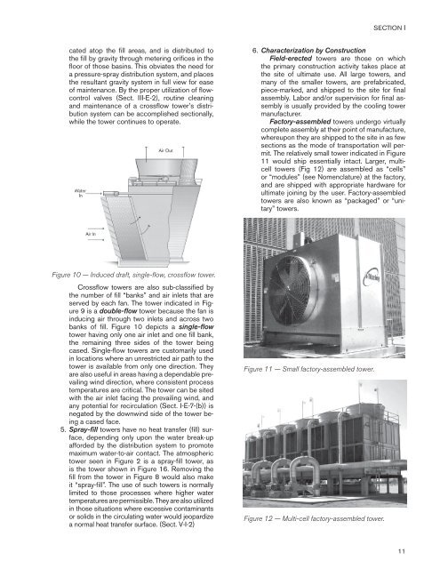
Figure 10 — Induced draft, single-flow, crossflow tower.<br />
Crossflow towers are also sub-classified by<br />
the number of fill “banks” and air inlets that are<br />
served by each fan. The tower indicated in Figure<br />
9 is a double-flow tower because the fan is<br />
inducing air through two inlets and across two<br />
banks of fill. Figure 10 depicts a single-flow<br />
tower having only one air inlet and one fill bank,<br />
the remaining three sides of the tower being<br />
cased. Single-flow towers are customarily used<br />
in locations where an unrestricted air path to the<br />
tower is available from only one direction. They<br />
are also useful in areas having a dependable prevailing<br />
wind direction, where consistent process<br />
temperatures are critical. The tower can be sited<br />
with the air inlet facing the prevailing wind, and<br />
any potential for recirculation (Sect. I-E-7-(b)) is<br />
negated by the downwind side of the tower being<br />
a cased face.<br />
5. Spray-fill towers have no heat transfer (fill) surface,<br />
depending only upon the water break-up<br />
afforded by the distribution system to promote<br />
maximum water-to-air contact. The atmospheric<br />
tower seen in Figure 2 is a spray-fill tower, as<br />
is the tower shown in Figure 16. Removing the<br />
fill from the tower in Figure 8 would also make<br />
it “spray-fill”. The use of such towers is normally<br />
limited to those processes where higher water<br />
temperatures are permissible. They are also utilized<br />
in those situations where excessive contaminants<br />
or solids in the circulating water would jeopardize<br />
a normal heat transfer surface. (Sect. V-I-2)<br />
SECTION I<br />
6. Characterization by Construction<br />
Field-erected towers are those on which<br />
the primary construction activity takes place at<br />
the site of ultimate use. All large towers, and<br />
many of the smaller towers, are prefabricated,<br />
piece-marked, and shipped to the site for final<br />
assembly. Labor and/or supervision for final assembly<br />
is usually provided by the cooling tower<br />
manufacturer.<br />
Factory-assembled towers undergo virtually<br />
complete assembly at their point of manufacture,<br />
whereupon they are shipped to the site in as few<br />
sections as the mode of transportation will permit.<br />
The relatively small tower indicated in Figure<br />
11 would ship essentially intact. Larger, multicell<br />
towers (Fig 12) are assembled as “cells”<br />
or “modules” (see Nomenclature) at the factory,<br />
and are shipped with appropriate hardware for<br />
ultimate joining by the user. Factory-assembled<br />
towers are also known as “packaged” or “unitary”<br />
towers.<br />
Figure 11 — Small factory-assembled tower.<br />
Figure 12 — Multi-cell factory-assembled tower.<br />
11