Cooling Tower Fundamentals - SPX Cooling Technologies
Cooling Tower Fundamentals - SPX Cooling Technologies
Cooling Tower Fundamentals - SPX Cooling Technologies

Create successful ePaper yourself
Turn your PDF publications into a flip-book with our unique Google optimized e-Paper software.
SECTION II<br />
46<br />
3. Riser Sway Braces: Wind and/or earthquake<br />
considerations will occasionally influence specifying<br />
engineers to call for sway braces which tie<br />
the upper end of a foundation-cantilevered riser<br />
to the larger tower structure, which is assumed<br />
by the specification writer to have the greater rigidity.<br />
This is not good practice when the riser<br />
is of a material having a high modulus of elasticity,<br />
such as steel. The cooling tower structure<br />
will react quite differently from the riser under<br />
an imposed load condition. For example, under<br />
earthquake acceleration the riser will respond at<br />
high frequency and low amplitude, whereas the<br />
tower structure (of lower modulus material) will<br />
respond at lower frequency and greater amplitude.<br />
The result is that any connection between<br />
the two will be attempting to transmit the seismic<br />
response of the tower into the more rigid risers,<br />
and damage to the endwall framing or the piping<br />
connections may follow.<br />
A riser brace capable of transmitting the high<br />
loads generated by a differential response is a<br />
costly auxiliary structure which imposes significant<br />
loadings at anchorage points in the cold<br />
water basin, and its utilization in such cases<br />
should be avoided. Properly designed cooling<br />
tower header piping will accommodate typical<br />
horizontal and vertical movement without distress,<br />
and the flanged joint between the riser<br />
and the distribution header should never be<br />
considered as a riser support. In cases of doubt,<br />
an expansion joint or flexible coupling should be<br />
provided between the riser and header to allow<br />
relative movement to occur.<br />
Risers of FRP plastic pipe have a modulus of<br />
elasticity close to that of the tower structure and<br />
will experience similar seismic response. Therefore,<br />
destructive transfer of opposed loads is<br />
unlikely, and the flexibility of the FRP pipe riser<br />
may require lateral support at the top. In such<br />
cases, a riser sway brace may be a desirable<br />
solution.<br />
4. Ancillary Systems: Provision must be made for<br />
make-up, overflow and blowdown, and should<br />
be made for by-pass. Since proper by-pass utilization<br />
is covered more fully in Sections I-H and<br />
V-F, suffice it here to say that the location of the<br />
by-pass should be in accordance with the manufacturer’s<br />
recommendations to prevent damage<br />
to the structure or the fill.<br />
The amount of make-up water required consists<br />
of the total water losses accrued through<br />
evaporation (Sect. I-D), drift (Sect. II-I), blowdown<br />
(Sect. I-G-1) and system leakage. On<br />
relatively small towers, make-up is controlled by<br />
a mechanical float valve responding to the basin<br />
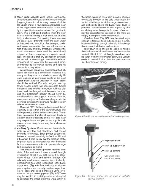
water level. (Fig. 65) Float switches or electric<br />
probe systems are normally used on larger towers<br />
to open and close a make-up valve, or to<br />
start and stop a make-up pump. (Fig. 66) These<br />
may be located in a stilling chamber designed<br />
to suppress the effect of normal wave action in<br />
the basin. Make-up lines from potable sources<br />
are usually brought to the cold water basin, installed<br />
with their point of discharge downturned,<br />
and sufficiently above the basin water level to<br />
preclude contamination of the supply by the<br />
circulating water. Non-potable water, of course,<br />
may be connected for injection of the make-up<br />
supply at any point in the water circuit.<br />
Overflow lines (Fig. 50) may be sized large<br />
enough to facilitate flush-out cleaning of a sump,<br />
but must be large enough to handle full make-up<br />
flow in case that device malfunctions.<br />
Blowdown lines should be sized to handle<br />
the maximum anticipated amount of water to be<br />
wasted. (Sect. I-G-1) Although blowdown can<br />
be taken from the cold water basin, it is usually<br />
easier to control if taken from the pressure-side<br />
(i.e. the inlet riser) piping.<br />
Figure 65 — Float-operated mechanical make-up valve.<br />
High water alarm<br />
Make-up supply cut-off<br />
Make-up demand<br />
Low water heater<br />
cut-off and alarm<br />
Figure 66 — Electric probes can be used to actuate<br />
various systems.