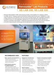
TT-AFM brochure (4.1 MB)
TT-AFM brochure (4.1 MB)
TT-AFM brochure (4.1 MB)

Create successful ePaper yourself
Turn your PDF publications into a flip-book with our unique Google optimized e-Paper software.
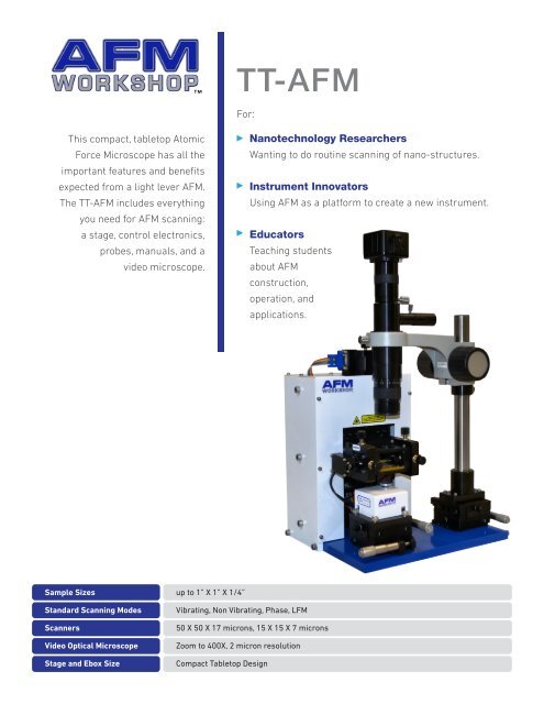
This compact, tabletop Atomic<br />
Force Microscope has all the<br />
important features and benefits<br />
expected from a light lever <strong>AFM</strong>.<br />
The <strong>TT</strong>-<strong>AFM</strong> includes everything<br />
Sample Sizes<br />
you need for <strong>AFM</strong> scanning:<br />
a stage, control electronics,<br />
Standard Scanning Modes<br />
Scanners<br />
Video Optical Microscope<br />
Stage and Ebox Size<br />
probes, manuals, and a<br />
video microscope.<br />
up to 1” X 1” X 1/4”<br />
Vibrating, Non Vibrating, Phase, LFM<br />
50 X 50 X 17 microns, 15 X 15 X 7 microns<br />
Zoom to 400X, 2 micron resolution<br />
Compact Tabletop Design<br />
<strong>TT</strong>-<strong>AFM</strong><br />
For:<br />
Nanotechnology Researchers<br />
Wanting to do routine scanning of nano-structures.<br />
Instrument Innovators<br />
Using <strong>AFM</strong> as a platform to create a new instrument.<br />
Educators<br />
Teaching students<br />
about <strong>AFM</strong><br />
construction,<br />
operation, and<br />
applications.
V1.4<br />
STAGE<br />
The <strong>TT</strong>-<strong>AFM</strong> stage has excellent<br />
thermal and mechanical stability<br />
required for high resolution <strong>AFM</strong><br />
scanning. Additionally, its open design<br />
facilitates user modification.<br />
1434 East 33rd St., Signal Hill, CA 90755 | P: (714) 402-8253<br />
Rigid Frame Design<br />
The crossed beam design for the stage support is extremely rigid so<br />
the <strong>AFM</strong> is less susceptible to external vibrations.<br />
Light Lever <strong>AFM</strong> Force Sensor<br />
Light lever force sensors are used in almost all atomic force<br />
microscopes and permit many types of experiments.<br />
Integrated Probe Holder/Probe Exchanger<br />
A unique probe holder and clipping mechanism allows quick and<br />
easy probe exchange.<br />
Direct Drive Z stage<br />
A linear motion stage is used to move the probe in a perpendicular<br />
motion to the sample. Probe/sample angle alignment is not required,<br />
facilitating a much faster probe approach.<br />
Small Footprint<br />
The stage dimensions of 7.5 X 12” require little space and fit easily on<br />
a tabletop.<br />
Precision XY Stage with Micrometer<br />
The sample is moved relative to the probe with a precision xy<br />
micrometer stage. Thus, the sample can be moved without<br />
touching it.<br />
Modes Electric Plug<br />
A six pole electrical plug is located at the back of the stage to<br />
expand the capabilities of the <strong>TT</strong>-<strong>AFM</strong>.<br />
XYZ Precision Piezo Scanner<br />
The modified tripod design utilizes temperature compensated strain<br />
gauges which assure accurate measurements from images. Also,<br />
with this design it is possible to rapidly zoom into a feature visualized<br />
in an image.<br />
Laser/Detector Alignment<br />
Both the light lever laser and the photo detector adjustment<br />
mechanism may be directly viewed. This feature simplifies the<br />
laser/detector alignment.<br />
Adaptable Sample Holder<br />
At the top of the XYZ scanner is a removable cap that holds the<br />
sample. The cap can be modified - or a new cap can be designed – to<br />
hold many types of samples.<br />
High resolution video microscope<br />
Direct drive Z motor stage<br />
Light lever force sensor<br />
Mode input/output plug<br />
XYZ linearized piezo scanner<br />
XY sample translation stage<br />
02
V1.4<br />
EBOX<br />
Electronics in the <strong>TT</strong>-<strong>AFM</strong> are<br />
constructed around industry standard<br />
USB data acquisition electronics. The<br />
critical functions, such as xy scanning,<br />
are optimized with a 24 bit digital to<br />
analog converter. With the analog z<br />
feedback loop, the highest fidelity<br />
scanning is possible. Vibrating mode<br />
scanning is possible with both phase<br />
and amplitude feedback using the high<br />
sensitivity phase detection electronics.<br />
1434 East 33rd St., Signal Hill, CA 90755 | P: (714) 402-8253<br />
24 bit scan DAC<br />
Scanning waveforms for generating precision motion in the X-Y axis<br />
with the piezo scanners are created with 24 bit DACS driven by a<br />
32 bit micro controller. With 24 bit scanning, the highest resolution<br />
<strong>AFM</strong> images may be measured. Feedback control using the xy strain<br />
gauges assures accurate tracking of the probe over the surface.<br />
Phase and Amplitude Detector Circuit<br />
Phase and amplitude in the Ebox are measured with highly stable<br />
phase and amplitude chips. The system can be configured to feed<br />
back on either phase or amplitude when scanning in vibrating mode.<br />
Signal Accessible<br />
At the rear of the eBox is a 50 pin ribbon cable that gives access to all<br />
of the primary electronic signals without having to open the eBox.<br />
Status Lights<br />
At the front of the Ebox is a light panel that has 7 lights. In<br />
the unlikely event of a circuit failure, these lights are used for<br />
determining the status of the Ebox power supplies.<br />
Precision Analog Feedback<br />
Feedback from the light lever force sensor to the Z piezoceramic is<br />
made using a precision analog feedback circuit. The position of the<br />
probe may be fixed in the vertical direction with a sample-and-hold<br />
circuit.<br />
Variable Gain High Voltage Piezo Drivers<br />
An improved signal to noise ratio, as well as extremely small scan<br />
ranges are possible with the variable gain high voltage piezo drivers.<br />
Microprocessor for scan generation through 24 bit DAC’s<br />
Low noise, variable gain high voltage amplifiers with PID feedback for XY<br />
scanning<br />
Dimensions: Width 6” | Height 10” | Depth 14”<br />
High fidelity, low noise z feedback circuits for accurate probe tracking<br />
Phase and amplitude detection circuits for vibrating mode <strong>AFM</strong><br />
Industry standard National Instruments USB data acquisition board<br />
Internally accessible header for signal input/output<br />
Eight channels of ADC for monitoring and displaying data with LabView<br />
software<br />
03
SOFTWARE<br />
Software for acquiring images<br />
is designed with the industry<br />
standard LabView programming<br />
visual interface instrument design<br />
environment. There are many<br />
standard functions, including setting<br />
scanning parameters, probe approach,<br />
frequency tuning, and displaying<br />
images in real time. LabView<br />
facilitates rapid development for those<br />
users seeking to enhance the software<br />
with additional special features.<br />
LabView also enables the <strong>TT</strong>-<strong>AFM</strong> to<br />
be readily combined with any other<br />
instrument using LabView VI.<br />
V1.4<br />
Pre-scan Window<br />
Scan Window<br />
LabView Window<br />
1434 East 33rd St., Signal Hill, CA 90755 | P: (714) 402-8253<br />
A pre-scan window<br />
includes all of the<br />
functions that are<br />
required before a scan<br />
is started. The functions<br />
are presented in a logical<br />
sequence on the screen.<br />
Once all of the steps in<br />
the pre-scan window<br />
are completed, the scan<br />
window is used for<br />
measuring images. Scan<br />
parameter, Z feedback<br />
parameters, and image<br />
view functions may be<br />
changed with dialogs on<br />
this screen.<br />
Industry standard<br />
programming<br />
environment.<br />
Readily customized<br />
and modified for<br />
specialized applications.<br />
Instrumentation already<br />
using Labview can be<br />
added to the <strong>TT</strong>-<strong>AFM</strong> to<br />
create new capabilities.<br />
04
IMAGE<br />
ANALYSIS<br />
SOFTWARE<br />
Included with the <strong>TT</strong>-<strong>AFM</strong> is the<br />
Gwyddion open source SPM image<br />
analysis software. This complete<br />
image analysis package has all<br />
the software functions necessary<br />
to process, analyze and display<br />
V1.4<br />
SPM images.<br />
1434 East 33rd St., Signal Hill, CA 90755 | P: (714) 402-8253<br />
» visualization: false color representation with different types of<br />
mapping<br />
» shaded, logarithmic, gradient- and edge-detected, local contrast<br />
representation, Canny lines<br />
» OpenGL 3D data display: false color or material representation<br />
» easily editable color maps and OpenGL materials<br />
» basic operations: rotation, flipping, inversion, data arithmetic, crop,<br />
resampling<br />
» leveling: plane leveling, profiles leveling, three-point leveling, facet<br />
leveling, polynomial background removal, leveling along user-defined<br />
lines<br />
» value reading, distance and angle measurement<br />
» profiles: profile extraction, measuring distances in profile graph,<br />
profile export<br />
» filtering: mean, median, conservative denoise, Kuwahara, minimum,<br />
maximum, checker pattern removal<br />
» general convolution filter with user-defined kernel<br />
» statistical functions: Ra, RMS, projected and surface area, inclination,<br />
histograms, 1D and 2D correlation functions, PSDF, 1D and 2D<br />
angular distributions, Minkowski functionals, facet orientation<br />
analysis<br />
» statistical quantities calculated from area under arbitrary mask<br />
» row/column statistical quantities plots<br />
» ISO roughness parameter evaluation<br />
» grains: threshold marking and un-marking, watershed marking<br />
» grain statistics: overall and distributions of size, height, area, volume,<br />
boundary length, bounding dimensions<br />
» integral transforms: 2D FFT, 2D continuous wavelet transform (CWT),<br />
2D discrete wavelet transform (DWT), wavelet anisotropy detection<br />
» fractal dimension analysis<br />
» data correction: spot remove, outlier marking, scar marking, several<br />
line correction methods (median, modus)<br />
» removal of data under arbitrary mask using Laplace or fractal<br />
interpolation<br />
» automatic xy plane rotation correction<br />
» arbitrary polynomial deformation on xy plane<br />
» 1D and 2D FFT filtering<br />
» fast scan axis drift correction<br />
» mask editing: adding, removing or intersecting with rectangles and<br />
ellipses, inversion, extraction, expansion, shrinking<br />
» simple graph function fitting, critical dimension determination<br />
» force-distance curve fitting<br />
» axes scale calibration<br />
» merging and immersion of images<br />
» tip modeling, blind estimation, dilation and erosion<br />
05
VIDEO<br />
MICROSCOPE Video microscope used to locate<br />
surface features for scanning.<br />
A video optical microscope in an <strong>AFM</strong><br />
serves three functions: aligning the<br />
laser onto the cantilever in the light<br />
lever <strong>AFM</strong>, locating surface features<br />
for scanning, and facilitating probe<br />
approach. The <strong>TT</strong>-<strong>AFM</strong> includes<br />
a high performance video optical<br />
microscope along with a 3 mega pixel<br />
ccd camera, light source, microscope<br />
stand, and Windows software for<br />
V1.4<br />
displaying images.<br />
PROBE HOLDER/<br />
EXCHANGE<br />
The <strong>TT</strong>-<strong>AFM</strong> utilizes a unique probe<br />
holder/exchange mechanism. Probes<br />
are held in place with a spring device<br />
that mates with a probe exchange<br />
tool. With the probe exchange<br />
tool, changing probes takes only a<br />
few minutes.<br />
Probe Exchange Tool<br />
1434 East 33rd St., Signal Hill, CA 90755 | P: (714) 402-8253<br />
The Vibrating Mode Cantilever is<br />
125 μ long.<br />
Laser alignment is greatly<br />
facilitated with the video optical<br />
microscope. This non-vibrating<br />
cantilever is 450 μ long. The red<br />
spot is from the laser reflecting<br />
off the cantilever.<br />
Probe Holder<br />
Probe Inserted in Clip<br />
06
V1.4<br />
<strong>TT</strong>-<strong>AFM</strong><br />
IMAGES<br />
With a vertical noise floor of 0.1 nm<br />
and a horizontal resolution of 2 nm,<br />
most types of samples may be imaged<br />
with the <strong>TT</strong>-<strong>AFM</strong>. These include hard<br />
as well as soft samples.<br />
OPEN DESIGN<br />
An open design is at the core of<br />
all products offered by the <strong>AFM</strong><br />
Workshop. New types of experiments<br />
are more readily designed and<br />
implemented through the use of Lab<br />
View software. All the mechanical<br />
drawings for the <strong>TT</strong>-<strong>AFM</strong> are available<br />
in the documentation package option.<br />
Finally, the company’s website offers<br />
a Users Forum to directly share<br />
specialized designs developed for the<br />
<strong>TT</strong>-<strong>AFM</strong>. For specialized applications,<br />
other types of scanners such as<br />
flexure and tubes can be easily added<br />
to the microscope stage.<br />
1434 East 33rd St., Signal Hill, CA 90755 | P: (714) 402-8253<br />
40 X 40 μ - Bacteria 3 X 3 μ – Phase Image<br />
30 X 30 μ Spores<br />
MEMS Multiple Level Gear<br />
2 X 2 μ - Si atomic terrace<br />
10 X 10 μ - Scratch in metal<br />
2 X 2 μ - BOPP polymer fiber<br />
40 X 40 μ – Test Pattern<br />
Test Pattern with defect<br />
4 X 4 μ -17 nm nanoparticles<br />
7 X 7 μ - Defect<br />
5 X 5 μ - Terraces<br />
1 X 1 μ - 278 nm test pattern<br />
25 X 25 μ - parasites 300 X 300 nm -Phase PMMA<br />
07
SCANNING<br />
MODES<br />
Standard with every <strong>TT</strong>-<strong>AFM</strong> are non-<br />
vibrating(NV) mode and vibrating(V)<br />
modes for making topography scans.<br />
Additional modes included with the<br />
product are lateral force imaging<br />
as well as phase mode imaging. All<br />
of the scanning modes that can be<br />
implemented with a light lever <strong>AFM</strong><br />
are possible with the <strong>TT</strong>-<strong>AFM</strong>.<br />
<strong>TT</strong>-<strong>AFM</strong><br />
OPTIONS<br />
Although the <strong>TT</strong>-<strong>AFM</strong> comes with<br />
everything you need to make<br />
<strong>AFM</strong> images, several options are<br />
V1.4<br />
currently available.<br />
1434 East 33rd St., Signal Hill, CA 90755 | P: (714) 402-8253<br />
With the window below, the resonance frequency of a cantilever is<br />
readily measured. Additionally, the phase characteristics of the probe<br />
sample interaction are captured.<br />
Environmental Cell<br />
Permits scanning in inert environments or liquids.<br />
Scanner Fabrication Tool<br />
Facilitates scanner fabrication.<br />
High Resolution Scanner<br />
Allows a range of 15 X 15 microns in XY and 7 microns in Z.<br />
Vibration Cabinet<br />
Reduces unwanted acoustic and structural vibrations.<br />
Conductive <strong>AFM</strong><br />
Measures the 2-D conductivity of sample surfaces.<br />
<strong>AFM</strong> Workshop regularly develops new Options.<br />
Contact <strong>AFM</strong> Workshop for more information on options for the <strong>TT</strong>-<strong>AFM</strong>.<br />
Vibration Enclosure Environmental Cell<br />
15 micron scanner<br />
08
SPECIFICATIONS<br />
50 Micron xyz Scanner<br />
» Type Modified tripod<br />
» XY Linearity < 1%<br />
» XY Range > 50 μ<br />
» XY resolution < 10 nm closed loop<br />
< 1 nm open loop<br />
» XY Actuator type Piezo<br />
» Sensor type Strain Gauge<br />
» Z Range > 16 μ<br />
» Z Linearity < 5 %<br />
» Z sensor noise < 5 nm<br />
» Z feedback noise < 0.2 nm*<br />
» Z Actuator Type Piezo<br />
» Z Sensor type Strain Gauge<br />
15 Micron xyz Scanner<br />
» Type Modified tripod<br />
» XY Linearity < 1%<br />
» XY Range > 15 μ<br />
» XY resolution < 3 nm closed loop<br />
< 0.3 nm open loop<br />
» XY Actuator type Piezo<br />
» Sensor type Strain Gauge<br />
» Z Range > 7 μ<br />
» Z Linearity < 5 %<br />
» Z sensor noise < 5 nm<br />
» Z feedback noise < 0.1 nm*<br />
» Z Actuator Type Piezo<br />
» Z Sensor type None<br />
Sample Holder<br />
» Type Magnet<br />
» Max Lateral Dimensions 1 inch<br />
» Max. Height 0.25 inch<br />
Light Lever <strong>AFM</strong> Force Sensor<br />
» Probe Types Industry standard<br />
» Probe insertion Manual – probe<br />
exchange tool<br />
» Probe holding mechanism Clip<br />
Vibrating mode piezo<br />
Electrical connector to<br />
probe<br />
» Laser/Detector adjustment range +/- 1.5 mm<br />
» Adjustment resolution 1 micron<br />
» Minimum Probe to Objective 25 mm<br />
» Laser Type 670 nm diode, < 5 mw<br />
» Detector<br />
Type 4 quadrant<br />
Band Width > 500 kHz<br />
Signals Transmitted TL, BL, TR, BR<br />
Gain Lo, High Settings<br />
» Probe sample angle 10 degrees<br />
V1.4<br />
1434 East 33rd St., Signal Hill, CA 90755 | P: (714) 402-8253<br />
XY Translator<br />
» Range 25.4 mm<br />
» Resolution 2 μ<br />
» Type Bearing - spring loaded<br />
» Lock Down Yes<br />
Z Motion<br />
» Type Direct Drive<br />
» Range 25 mm<br />
» Drive Type Stepper Motor<br />
» Min. Step Size 330 nm<br />
» Slew Rate 8 mm/minute<br />
» Limit Switch Top, Bottom<br />
» Control Software – rate, step size<br />
Digital Data Input Output<br />
» Connection USB<br />
» Scanning DAC<br />
Number 2<br />
Bits 24<br />
Frequency 7 kHz<br />
» Control DAC<br />
Number 2<br />
Bits 14<br />
Frequency 2 kHz<br />
» ADC<br />
Number 8<br />
Bits 14<br />
Frequency 48 kHz<br />
Analog Electronics<br />
» Vibrating Mode<br />
Freq Range 2 kHz – 800 kHz<br />
Output Voltage 10 Vpp<br />
Demod. Freq TBD<br />
» Z Feedback<br />
Type PID<br />
Bandwidth > 3 kHz<br />
Sample Hold Yes<br />
Voltage 0-150 V<br />
» XY Scan<br />
Voltage 0 – 150 V<br />
bandwidth > 200 Hz<br />
Pan & Zoom 22 Bits<br />
» Tip Approach Cutoff > 20 μ sec.<br />
09
SPECIFICATIONS<br />
V1.4<br />
C o n t i n u e d<br />
Software<br />
» Environment Lab View<br />
» Operating System Windows 7<br />
» Image Acquisition Real Time Display<br />
(2 of 8 channels)<br />
» Control Parameters<br />
PID Yes<br />
Setpoint Yes<br />
Range Yes<br />
Scan Rate Yes<br />
Image Rotate 0 and 90 degrees<br />
» Laser Align Yes<br />
» Vibrating Freq. Display Yes<br />
» Force Distance Yes<br />
» Tip Approach Yes<br />
» Oscilloscope Yes<br />
» Image Store Format Industry Standard<br />
» Image Pixels 16 X 16 to 1024 X 1024<br />
» H.V. Gain Control XY and Z<br />
» Real time display Line Level, Light Shaded,<br />
Grey Color Pallet<br />
» Calibration System Window<br />
» Probe Center Yes<br />
» Video Microscope<br />
Field of view<br />
Resolution<br />
1434 East 33rd St., Signal Hill, CA 90755 | P: (714) 402-8253<br />
Working Distance<br />
Magnification<br />
Minimum Zoom<br />
2 X 2 mm<br />
20 μ<br />
114 mm<br />
45 X<br />
» Computer Industry Standard<br />
Computer<br />
Maximum Zoom<br />
300 X 300 u<br />
2 μ<br />
114 mm<br />
400X<br />
* Z Noise performance depends greatly on the environment the<br />
<strong>TT</strong>-<strong>AFM</strong> is used in. Best Z noise performance is obtained in a<br />
vibration free environment.<br />
** Every effort is made to present accurate specifications,<br />
however, due to circumstances out of the <strong>AFM</strong>Workshop’s<br />
control specifications are subject to change.<br />
10