EpiCurve® TT for AIXTRON Close Coupled Showerhead ... - Laytec
EpiCurve® TT for AIXTRON Close Coupled Showerhead ... - Laytec
EpiCurve® TT for AIXTRON Close Coupled Showerhead ... - Laytec

You also want an ePaper? Increase the reach of your titles
YUMPU automatically turns print PDFs into web optimized ePapers that Google loves.
<strong>EpiCurve®</strong> <strong>TT</strong> features:<br />
Curvature<br />
Temperature<br />
Reflectance<br />
Communication / integration<br />
Measurable growth<br />
parameters<br />
Datasheet<br />
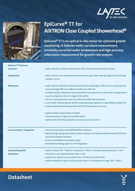
<strong>EpiCurve®</strong> <strong>TT</strong> <strong>for</strong><br />
<strong>AIXTRON</strong> <strong>Close</strong> <strong>Coupled</strong> <strong>Showerhead</strong>®<br />
<strong>EpiCurve®</strong> <strong>TT</strong> is an optical in-situ sensor <strong>for</strong> epitaxial growth<br />
monitoring. It features wafer curvature measurement,<br />
emissivity corrected wafer temperature and high-accuracy<br />
reflectance measurement <strong>for</strong> growth rate analysis.<br />
• wafer selective curvature measurement with a 2-dimensional detection system<br />
• wafer selective true temperature measurements, pyrometer calibrated against a black body<br />
radiation source<br />
• wafer selective reflectance measurements at two wavelengths: 950 nm and a customized sec-<br />
ond wavelength (405 nm or 488 nm or 633 nm or 950 nm)<br />
• multiple position reflectance and temperature measurements in multi-wafer configurations<br />
(e.g. <strong>for</strong> comparison center to edge on the wafer)<br />
• line scan measurements across the wafers <strong>for</strong> uni<strong>for</strong>mity evaluation<br />
• on-line wafer selective growth rate fits using virtual layer approach or alternatively oscillator fits<br />
• recipe controlled automated growth rate fit <strong>for</strong> multi-layer structures<br />
• optical wobble compensation included<br />
• measurements on single and multiple wafers<br />
• optimized <strong>for</strong> 24 h/7day operation in production environment<br />
• direct communication with <strong>AIXTRON</strong> AIXact software<br />
• data exchange with growth system control computer via hardware interface and/or TCP/IP protocol<br />
based software interface<br />
• remote controllable from growth recipe<br />
• heartbeat/watchdog signals <strong>for</strong> SPS integration<br />
• wafer curvature 1/R: - 7000 km-1 (convex) to + 750 km-1 (concave), typical accuracy: ± 3 km-1 • reflectance: noise typically better than ± 0.5%<br />
• growth rate: typical accuracy better than ± 1% (down to 0.001 nm/s)<br />
• wafer temperature: typical accuracy better than ± 1K: temperature range: 500 – 1400°C
<strong>EpiCurve®</strong> <strong>TT</strong> <strong>for</strong> <strong>AIXTRON</strong> CCS® standard package<br />
15 pin interface cable (5 m): trigger pulse<br />
2 fibre optical cables (10 m)<br />
Epi<strong>TT</strong><br />
optical<br />
head<br />
EpiCurve<br />
optical head<br />
<strong>EpiCurve®</strong> optical head <strong>for</strong><br />
curvature measurements<br />
Epi<strong>TT</strong> optical head <strong>for</strong> combined<br />
reflectance and wafer temperature<br />
measurements<br />
Electronic control unit<br />
growth system<br />
and growth computer<br />
(not delivered by LayTec)<br />
9-pin power supply cable (10 m)<br />
2D detector cable (10 m)<br />
Miscellaneous items • reactor specific mounting and adjustment unit<br />
• manual and software CD<br />
• additional USB license dongle <strong>for</strong> growth rate analysis and growth rate fit on office computer<br />
• special coated 2”, 3” or 4” Al-Si eutectic wafer <strong>for</strong> temperature calibration<br />
• curvature calibration wafers (2“, 3“ or 4“), one convex and one concave, characterized<br />
* In CRIUS 30 x 2” measurements on all wafers are possible <strong>for</strong> rotation speed ≤ 75 rpm<br />
electronic control unit<br />
SH 100-200<br />
electrical<br />
cable (2 m)<br />
LAN connection (optional)<br />
light source <strong>for</strong> curvature measurement compact 656 nm laser diode<br />
typical life-time according to manufacturer 15.000 h<br />
curvature (1/R) detection limits -7000 km-1 to +750 km-1 bowing<br />
maximum curvature (1/R) resolution ± 3 km-1 curvature sampling rate 1 point per wafer (triggered to center) and susceptor<br />
revolution, max. rate 10 Hz*<br />
light source <strong>for</strong> reflectance measurement combination of ultra high brightness LEDs<br />
typical life-time according to manufacturer 20.000 h<br />
reflectance measurement wavelength<br />
633 nm± 1.5 nm or 488 nm ± 5 nm or<br />
and bandwidth<br />
405 nm ± 5 nm or 950 nm ± 1 nm<br />
pyrometry wavelength and bandwidth 950 nm ± 5 nm<br />
typical sampling rate 2...5 kHz<br />
data repetition rate 4 revolutions of main susceptor<br />
The control unit is a standard 19” case that can be easily mounted into existing 19” racks. It is<br />
connected with the control computer and the growth system as shown in the drawing above.<br />
Control computer • 19” rack mount control computer<br />
• CPU: Pentium Core 2 Duo, min 1.66 GHz, RAM min. 1 GB<br />
• HDD min. 160 GB, RAID 1<br />
• DVD-writer, card reader, mouse, keyboard<br />
• 100 Mbit/s LAN interface or better<br />
• operating system: Windows XP pro MUI (multi language version)<br />
• 19” TFT flat screen (monitor resolution of 1280 x 1024 or higher)<br />
VHDCI trigger<br />
cable (2 m)<br />
control computer<br />
2
<strong>EpiCurve®</strong> <strong>TT</strong> <strong>for</strong> <strong>AIXTRON</strong> CCS® standard package<br />
Cables • 2 optical fibres (10 m, optical head Epi<strong>TT</strong> electronic unit), the minimum bending radius<br />
Communication with<br />
growth system<br />
of the fiber cables is 36 cm<br />
• 9-pin power supply cable (10 m, optical head <strong>EpiCurve®</strong> electronic unit)<br />
• 2D detector cable (10 m, optical head <strong>EpiCurve®</strong> computer)<br />
• SH 100-200 electrical cable (2 m, electronic unit computer)<br />
• optionally, a KVM extension set (cable or ethernet based extender) is available<br />
• 15 pin interface cable (5 m, electronic unit growth system): transfers the trigger and marker<br />
signals; exports analog voltages proportional to the measured temperature and reflectance<br />
(see “communication with growth system” below)<br />
• VHDCI trigger cable (2 m, 2D detector unit computer)<br />
• multi-plug and power cables<br />
The electronic control unit is connected with the growth system by a 15 pin interface cable<br />
(trigger pulse is mandatory). Optional LAN connection to growth control computer is available.<br />
Please note: <strong>for</strong> the LAN connection a special software interface on the growth system computer<br />
is necessary. The interface should be arranged by the customer with the manufacturer<br />
of the growth system.<br />
Communication features 15 pin interface cable LAN connection<br />
rotation synchronous trigger pulse or (once per 5V <strong>TT</strong>L or open<br />
–<br />
susceptor revolution) from growth system* collector signal<br />
2 digital signals to growth system indicating 5V <strong>TT</strong>L or open<br />
–<br />
heartbeat and busy/error status<br />
collector signal<br />
start/stop signal from growth system <strong>for</strong> remote 5V <strong>TT</strong>L or open via TCP/IP<br />
control from the recipe<br />
collector signal<br />
reflectance calibration signal from growth sys- 5V <strong>TT</strong>L or open via TCP/IP<br />
tem to indicate substrate reflectance<br />
collector signal<br />
up to 3 marker signals to indicate different 5V <strong>TT</strong>L or open via TCP/IP<br />
growth steps and <strong>for</strong> data synchronization with<br />
the growth recipe<br />
collector signal<br />
process temperature from thermocouple or analog voltage via TCP/IP<br />
Eurotherm <strong>for</strong> advanced logging and calibration<br />
purpose<br />
(0-10 V)<br />
pyrometer temperature to growth system <strong>for</strong> analog voltage** via TCP/IP<br />
export of measured temperature (uncorrected (0-10 V)<br />
(all wafers indi-<br />
or corrected)<br />
vidually)<br />
reflectance signal to growth system <strong>for</strong> export analog voltage** via TCP/IP<br />
of the measured reflectance<br />
(0-10 V)<br />
(all wafers individually)<br />
<strong>EpiCurve®</strong> <strong>TT</strong> size and weight Parts Size X x Y x Z mm Weight, kg<br />
optical curvature head <strong>EpiCurve®</strong> 150 x 203 x 66 2.0<br />
optical head Epi<strong>TT</strong> 50 x 100 x 150 0.5<br />
control unit (19” rack 4 HE, 84 TE) 450 x 300 x 180 8.0<br />
rack mount control computer (4 HE) 450 x 600 x 180 17.0<br />
19” LCD display 410 x 20 x 420 5,5<br />
mounting and adjustment unit reactor specific reactor specific<br />
* this line is mandatory <strong>for</strong> multiple wafer systems and strongly recommended <strong>for</strong> motor driven single-wafer systems<br />
** in multi-wafer systems only averaged data or data from one specified wafer can be transferred<br />
3
<strong>EpiCurve®</strong> <strong>TT</strong> <strong>for</strong> <strong>AIXTRON</strong> CCS® requirements<br />
Requirements to the<br />
growth system<br />
Operating conditions<br />
<strong>EpiCurve®</strong> <strong>TT</strong> electrical connections<br />
/ power consumption<br />
• 2 standard normal-incidence optical view ports on the same wafer ring: one 3° tilted view<br />
port <strong>for</strong> curvature and one <strong>for</strong> Epi<strong>TT</strong> head (reflectance and temperature measurement)<br />
• rotation synchronous trigger pulse from rotation axis, one pulse per revolution (<strong>TT</strong>L or open<br />
collector)<br />
• <strong>for</strong> remote control hardware and/or LAN connection between MOCVD system and Epi-<br />
Curve® <strong>TT</strong> (to be arranged with Aixtron Ltd.)<br />
• feed-throughs <strong>for</strong> two fibers, 2D detector cable and <strong>EpiCurve®</strong> optical head power supply cable<br />
min Ø: 40 mm (feed-through plate <strong>for</strong> KF40 recommended and available)<br />
Component<br />
Allowed temperature range<br />
operation storage<br />
optical head 10°C – 50°C 10°C – 60°C<br />
electronic control unit 10°C – 35°C 10°C – 60°C<br />
control computer 10°C – 35°C 10°C – 60°C<br />
• vibrations of optical head have to be avoided during the measurement<br />
• optical head is fragile, avoid shock-treatment<br />
• warm-up time: