fm2460-Qwik Jon Ultima 204 Installation Ins. - Pump Express
fm2460-Qwik Jon Ultima 204 Installation Ins. - Pump Express
fm2460-Qwik Jon Ultima 204 Installation Ins. - Pump Express

Create successful ePaper yourself
Turn your PDF publications into a flip-book with our unique Google optimized e-Paper software.
NOTICE TO INSTALLER: <strong>Ins</strong>tructions must remain with installation. SECTION: 6.10.065<br />
FM2460<br />
Product information presented<br />
here re fl ects con di tions at time<br />
of publication. Consult factory<br />
re gard ing dis crep an cies or<br />
in con sis ten cies.<br />
Patent Pending<br />
1. To help reduce the risk of elec tri cal shock, a properly<br />
ground ed re cep tacle or con trol box of grounding type must<br />
be in stalled and pro tect ed by a ground fault circuit interrupter<br />
(GFCI) in ac cor dance with the Na tion al Electrical Code and<br />
applicable local codes. Never re move ground pin from plug.<br />
If pump is wired direct, a GFCI must be installed in the control<br />
box. (SEE WARNING BELOW)<br />
2. Make certain that the ground fault in ter rupt er protected<br />
re cep tacle or control box is with in reach of the pump’s power<br />
supply cord. DO NOT USE AN EXTENSION CORD. Ex ten sion<br />
cords that are too long or too light do not deliver suffi cient voltage<br />
to the pump motor. But more im por tant, they could present a<br />
safety hazard if the insulation were to become damaged or the<br />
con nec tion end were to fall into a damp or wet area.<br />
3. Make sure the pump's elec tri cal sup ply cir cuit is equipped<br />
with fuses or circuit break ers of prop er capacity. A sep a rate<br />
branch circuit, sized ac cord ing to the National Electrical Code<br />
for the current shown on the pump name plate is recommended.<br />
(See Note 3.)<br />
4. TESTING FOR GROUND. As a safe ty mea sure, each elec tri cal<br />
outlet should be checked for ground using an Un der writ ers<br />
Lab o ra to ry Listed cir cuit an a lyz er which will indicate if the<br />
power, neutral and ground wires are cor rect ly con nected to your<br />
outlet. If they are not, call a qualifi ed licensed electrician.<br />
5. FOR YOUR PRO TEC TION ALWAYS DIS CON NECT PUMP<br />
FROM ITS POW ER SOURCE BE FORE HAN DLING. If pump<br />
is wired direct, de-energize the circuit at the control box.<br />
Ground ed pumps are supplied with a 3-prong grounded plug<br />
to help protect you against the possibility of elec tri cal shock.<br />
DO NOT UNDER ANY CIRCUM STANCES RE MOVE THE<br />
GROUND PIN. To re duce the risk of elec tri cal shock, a properly<br />
grounded receptacle or control box of grounding type must be<br />
installed and protected by a ground fault circuit interrupter (GFCI)<br />
in ac cor dance with National Elec tri cal Code and ap pli ca ble<br />
local codes.<br />
6. <strong><strong>Ins</strong>tallation</strong> and checking of elec tri cal cir cuits and hard ware<br />
should only be performed by a qual i fi ed li censed electrician.<br />
7. According to the state of California (Prop 65), this product<br />
contains chemicals known to the state of California to cause<br />
cancer and birth defects or other reproductive harm.<br />
MAIL TO: P.O. BOX 16347 • Louisville, KY 40256-0347<br />
SHIP TO: 3649 Cane Run Road • Louisville, KY 40211-1961<br />
(502) 778-2731 • 1 (800) 928-PUMP • FAX (502) 774-3624<br />
QWIK JON ® ULTIMA <strong>204</strong> SYSTEMS<br />
INSTALLATION INSTRUCTIONS<br />
PREINSTALLATION CHECKLIST<br />
© Copyright 2009 Zoeller Co. All rights reserved.<br />
visit our web site:<br />
www.zoeller.com<br />
1. <strong>Ins</strong>pect all materials. Oc ca sion ally, products are damaged dur ing ship ment. If the unit is damaged, contact your dealer be fore<br />
using. Do Not remove the test plugs from the pump.<br />
2. Carefully read all the lit era ture pro vid ed to fa mil iar ize your self with specifi c details re gard ing in stal la tion and use be fore<br />
at tempt ing the in stal la tion. These ma te ri als should be retained for future reference.<br />
0909<br />
Supersedes<br />
1007<br />
MODEL NO. ____________________<br />
DATE CODE: __________________<br />
DATE INSTALLED: _____________<br />
SEE BELOW FOR LIST OF WARNINGS SEE BELOW FOR LIST OF CAUTIONS<br />
1. Check to be sure your power source is ad e quate to handle<br />
the am per age requirements of the motor as indicated on the<br />
pump or unit I.D. tag.<br />
2. All plumbing (discharge and vent lines) must be installed<br />
to meet local codes. Unit must be vent ed. Do not use an<br />
automatic plumbing vent device.<br />
3. Maximum operating tem pera ture for model <strong>204</strong> must not<br />
exceed 104°F (40°C). Duty cycle should not exceed 30<br />
seconds on/30 seconds off.<br />
4. Do not use cleaning products containing bleach in the attached<br />
fi xtures as they will degrade the pump seals.<br />
NOTES<br />
SEE BELOW FOR LIST OF NOTES<br />
1. Repair and service should be performed by an Authorized<br />
Service Station only. (Consult Factory.)<br />
2. NOTE: Recommended for installations up to 20' total dynamic<br />
head. Consult Factory if installation is above 15' vertical<br />
height in 1" pipe. Mini-Grinder <strong>Pump</strong> is de signed for use in<br />
<strong>Qwik</strong> <strong>Jon</strong>® <strong>Ultima</strong> units only. It is not designed for use in any<br />
other application.<br />
3. Mini-grinder pump is rated for 115V, 60 Hz, 7 Amps, .5 HP.<br />
4. NOTE: <strong>Pump</strong>s with the “UL” mark and pumps with the<br />
“US” mark are tested to UL Standard UL778. CSA Certifi ed<br />
pumps are certifi ed to CSA Standard C22.2 No. 108. <strong>Qwik</strong><br />
<strong>Jon</strong>® <strong>Ultima</strong> units only. It is not designed for use in any other<br />
application.<br />
5. All fi xtures connecting to the system must be on the same<br />
fl oor level.<br />
REFER TO WARRANTY ON PAGE 2.
Manufacturer warrants, to the purchaser and subsequent owner during<br />
the warranty period, every new product to be free from defects in material<br />
and workmanship under normal use and service, when properly used<br />
and maintained, for a period of one year from date of purchase by the<br />
end user, or 18 months from date of original manufacture of the product,<br />
whichever comes fi rst. Parts that fail within the warranty period, one<br />
year from date of purchase by the end user, or 18 months from the<br />
date of original manufacture of the product, whichever comes fi rst, that<br />
inspections determine to be defective in material or workmanship, will be<br />
repaired, replaced or remanufactured at Manufacturer's option, provided<br />
however, that by so doing we will not be obligated to replace an entire<br />
assembly, the entire mechanism or the complete unit. No allowance<br />
will be made for shipping charges, damages, labor or other charges<br />
that may occur due to product failure, repair or replacement.<br />
This warranty does not apply to and there shall be no warranty for<br />
any material or product that has been disassembled without prior<br />
approval of Manufacturer, subjected to misuse, misapplication, neglect,<br />
alteration, accident or act of God; that has not been installed, operated or<br />
maintained in accordance with Manufacturer's installation instructions;<br />
that has been exposed to outside substances including but not limited<br />
to the following: sand, gravel, cement, mud, tar, hydrocarbons,<br />
hydrocarbon derivatives (oil, gasoline, solvents, etc.), or other abrasive<br />
or corrosive substances, wash towels or feminine sanitary products,<br />
Helpful Hints For Easy <strong><strong>Ins</strong>tallation</strong><br />
1. Read all instructions before beginning installation.<br />
2. Be sure the fl oor is level within 1/8".<br />
3. Use soapy water to lubricate all seals to aid<br />
in stal la tion.<br />
4. <strong>Ins</strong>tall rubber coupling/union in vent line to aid<br />
dis as sem bly.<br />
5. Do not use an automatic plumbing vent device.<br />
6. Obtain model number and date code, and record<br />
in for ma tion in the space provided on the front of<br />
this manual. Refer to this information when calling<br />
Fac to ry.<br />
Limited Warranty<br />
© Copyright 2009 Zoeller Co. All rights reserved.<br />
2<br />
etc. in all pumping applications. The warranty set out in the paragraph<br />
above is in lieu of all other warranties expressed or implied; and we<br />
do not authorize any representative or other person to assume for us<br />
any other liability in connection with our products.<br />
Contact Manufacturer at, 3649 Cane Run Road, Lou is ville, Ken tucky<br />
40211, Attention: Cus tom er Ser vice De part ment to obtain any need ed<br />
repair or re place ment of part(s) or additional in for ma tion pertaining<br />
to our warranty.<br />
MANUFACTURER EXPRESSLY DIS CLAIMS LI A BIL I TY FOR<br />
SPE CIAL, CON SE QUEN TIAL OR IN CI DEN TAL DAM AG ES OR<br />
BREACH OF EX PRESSED OR IMPLIED WARRANTY; AND<br />
ANY IMPLIED WAR RAN TY OF FIT NESS FOR A PAR TIC U LAR<br />
PUR POSE AND OF MER CHANT ABIL I TY SHALL BE LIM IT ED TO<br />
THE DU RA TION OF THE EX PRESSED WAR RAN TY.<br />
Some states do not allow limitations on the duration of an implied<br />
warranty, so the above limitation may not apply to you. Some states<br />
do not allow the exclusion or limitation of incidental or con se quen tial<br />
dam ag es, so the above lim i ta tion or exclusion may not apply to you.<br />
This warranty gives you specifi c legal rights and you may also have<br />
other rights which vary from state to state.<br />
Do’s And Don't’s For <strong>Ins</strong>talling A Unit<br />
1. DO read all installation material with the unit.<br />
2. DO inspect unit for any visible damage caused<br />
by shipping. Contact dealer if unit appears to be<br />
damaged.<br />
3. DO clean all visible debris from the unit.<br />
4. DO always disconnect pump from power source before<br />
han dling. DO always connect to a separately protected<br />
and prop er ly grounded ground fault protected circuit.<br />
DO NOT ever cut, splice or damage power cord. DO<br />
NOT carry or lift pump by its power cord. DO NOT<br />
use an extension cord.<br />
5. DO install a ball or gate valve and a union in the<br />
discharge line downstream of the check valve.<br />
6. DO test pump immediately after installation to be sure<br />
that the system is working properly.<br />
7. DO review all applicable local and national codes<br />
and verify that the installation conforms to each of<br />
them.<br />
8. We DO NOT recommend this product be connected<br />
to utilities other than those found in a normal<br />
bathroom application. Washing machines and<br />
dishwashers are examples of equipment that we Do<br />
Not recommend.<br />
9. DO inspect and test system for proper operations at<br />
least every 3 months.
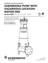
Typical Piping Confi gurations<br />
NOTE: All installations must comply with all ap pli ca ble Electrical and Plumbing Codes, in clud ing, but not<br />
limited, to Na tion al Elec tri cal Code; Local; Re gional and/or State Plumbing Codes, etc.<br />
1<br />
6<br />
<strong><strong>Ins</strong>tallation</strong> may not<br />
be exactly as shown.<br />
Service Parts<br />
Item Description Part No.<br />
1 <strong>Qwik</strong> <strong>Jon</strong> ® <strong>Ultima</strong> Model <strong>204</strong> System <strong>204</strong>-1000<br />
2 N202 replacement pump with discharge pipe 017374<br />
3 Tank cover with discharge fi tting 018533<br />
4 Tank 018534<br />
5 Seal 017350<br />
6 Float switch assembly 018532<br />
© Copyright 2009 Zoeller Co. All rights reserved.<br />
3<br />
3<br />
4<br />
5<br />
2<br />
SK2671<br />
SK2587
CONDITION POSSIBLE CAUSE REMEDY<br />
A. PUMP WILL NOT START OR<br />
RUN.<br />
B. PUMP STARTS TOO SOON.<br />
C. WATER LEVEL EXCESSIVE<br />
BE FORE PUMP TURNS ON.<br />
D. PUMP WILL NOT SHUT OFF<br />
OR RUNS TOO LONG BEFORE<br />
WATER IS PUMPED.<br />
E. PUMP OPERATES BUT<br />
DELIVERS LITTLE OR NO<br />
WATER.<br />
Low voltage, blown fuse, open<br />
circuit.<br />
Impeller bound.<br />
© Copyright 2009 Zoeller Co. All rights reserved.<br />
4<br />
Have a qualifi ed electrician check fuse<br />
and cir cuit.<br />
Motor or wiring shorted.<br />
Contact a Zoeller Service Station.<br />
Debris on fl oat switch. Remove debris<br />
Float “ON” point is adjusted too<br />
low.<br />
Raise the fl oat stops, make sure the<br />
fl oat is be tween the two stops.<br />
Float “ON” point adjusted to high. Lower the upper fl oat stop.<br />
<strong>Pump</strong> not plugged into piggyback<br />
fl oat switch receptacle.<br />
Ensure pump is not plugged directly<br />
into the outlet. Plug pump into<br />
piggyback fl oat switch receptacle.<br />
Debris under fl oat. Remove debris from around fl oat.<br />
Faulty fl oat switch. Contact a Zoeller Service Station.<br />
Float “Off” point adjusted too low. Raise the lower fl oat stop.<br />
<strong>Pump</strong> is air locked.<br />
Make sure vent hole in discharge<br />
pipe is clear.<br />
Water level too low. Raise the lower fl oat stop.<br />
Debris around intake. Clean area around intake.<br />
Blockage in discharge pipe. Remove pipe and fl ush out debris.<br />
Low or incorrect voltage.<br />
Have a qualifi ed electrician check<br />
house wir ing.<br />
Damaged Impeller. Contact a Zoeller Service Station.<br />
Incorrect fl oat adjustment.<br />
<strong>Pump</strong> is air locked.<br />
Vertical lift too high.<br />
Before servicing a pump, always shut off<br />
the main power breaker and then unplug the pump -<br />
making sure you are wearing insulated protective sole<br />
shoes and not standing in water. Under fl ooded conditions,<br />
contact your local electric company or a qualifi ed licensed<br />
electrician for disconnecting electrical service prior to pump<br />
removal.<br />
Submersible pumps contain oil which become<br />
pres sured and hot under operating conditions - allow 2½<br />
hours after dis con nect ing before at tempt ing ser vice.<br />
Contact Technical Service<br />
Department.<br />
Make sure vent hole in discharge<br />
pipe is clear.<br />
Change discharge piping or contact<br />
Technical Service Department.<br />
If the above checklist does not solve the problem, consult<br />
Zoeller Technical Service Department 1-(800) 928-PUMP<br />
- Do not attempt to service or otherwise dis as sem ble<br />
pump.<br />
CARE OF FINISH: Soap and water is all that is recommended<br />
for cleaning the outside of the tank. Other cleaning products<br />
may cause discoloration and scratching.
<strong>Qwik</strong> <strong>Jon</strong> ® <strong>Ultima</strong> <strong>Qwik</strong> Reference Guide<br />
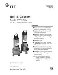
STEP 1 Location Selection<br />
Plan your new installation carefully.<br />
Floor: The fl oor should be structurally sound<br />
and level within 1/8". If the fl oor is not level,<br />
use hydraulic cement or similar material to<br />
level the fl oor.<br />
Water: A water supply will be needed to operate<br />
the shower and lav.<br />
Electrical: A 115 volt GFCI receptacle will<br />
be needed to supply electrical power to the<br />
pump.<br />
Sewage: Access to a sewage line is required.<br />
The <strong>Qwik</strong> <strong>Jon</strong>® <strong>Ultima</strong> requires a 1" (or 3/4" if<br />
your codes permit) sewage discharge line to<br />
connect to an existing sewage line. A ball or<br />
gate valve should be installed in the discharge<br />
line.<br />
Vent: Access to a vent pipe is required. The<br />
use of a mechanical vent system is NOT<br />
recommended.<br />
NOTE: If a built-in installation is to be used,<br />
locate the pump unit in an area that will allow<br />
access to the pump and switch.<br />
GFCI<br />
OUTLET<br />
STEP 2 Leveling of <strong>Pump</strong> Unit<br />
Do not use wooden shims to level the pump unit!<br />
Ensure that nails, screws or other sharp objects do<br />
not puncture the pump unit!<br />
Level the pump unit to within 1/8" using hydraulic cement or<br />
similar material.<br />
© Copyright 2009 Zoeller Co. All rights reserved.<br />
5<br />
DISCHARGE<br />
PIPE<br />
BALL OR GATE VALVE<br />
SOLD SEPARATELY.<br />
LEVEL FLOOR<br />
VENT<br />
PIPE<br />
SK2672<br />
SK2673
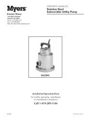
STEP 3 Piping<br />
1) Adding bathroom fi xtures - The <strong>Qwik</strong> <strong>Jon</strong>® <strong>Ultima</strong><br />
is designed to accept bathroom fi xtures utilizing the<br />
two side inlets. These inlets can be attached via the<br />
2" MPT (outside diameter) or the 1½" slip (inside<br />
diameter). These inlets must have the inner portion<br />
drilled out using a 1¾" hole saw(see Figure 3.2).<br />
This is to ensure there is no leakage problems from<br />
inlets not in use. When utilizing side inlets, install a<br />
check valve on the incoming line.<br />
2) Cut and dry-fi t the pipe and fi ttings as required for<br />
1" diameter discharge pipe (may be reduced to 3/4"<br />
diameter if codes permit).<br />
3) While dry-fi tting the discharge pipe, position and mark<br />
the location of the pump unit discharge fi tting.<br />
Discharge Vent<br />
DRILL POINT<br />
© Copyright 2009 Zoeller Co. All rights reserved.<br />
6<br />
4) Cut and dry-fi t 1-1/2" vent pipe as required to ensure<br />
that the vent pipe does not interfere with other<br />
components. Make the connection to the pump unit<br />
with the provided street elbow. A 2" x 1" 90° discharge<br />
fi tting has been provided, however, it may be easier<br />
to pipe straight up depending on the installation.<br />
Proper venting is required. Do not use a<br />
mechanical type vent.<br />
5) Clean, prime and solvent weld the inlet and discharge<br />
piping and pump unit discharge fi tting.<br />
When applying solvent weld to discharge<br />
fi tting, ensure that none gets into the check valve assembly<br />
(see Figure 5.3). Pay close attention to the proper alignment<br />
of the discharge fi tting previously marked above.<br />
6) Clean and solvent weld vent piping as required for<br />
proper venting.<br />
2" MPT OUTSIDE<br />
1-1/2" SLIP INSIDE<br />
Do not put glue in this area.<br />
Figure 3.1 Figure 3.2 Figure 3.3<br />
SK2673 SK2586<br />
SKxxxx
STEP 3 NOTES<br />
© Copyright 2009 Zoeller Co. All rights reserved.<br />
7
www.zoeller.com<br />
MAIL TO: P.O. BOX 16347<br />
Louisville, KY 40256-0347<br />
SHIP TO: 3649 Cane Run Road<br />
Louisville, KY 40211-1961<br />
(502) 778-2731 • 1 (800) 928-PUMP<br />
FAX (502) 774-3624<br />
© Copyright 2009 Zoeller Co. All rights reserved.<br />
8<br />
Manufacturers of . .