Menards ATV Sport Shelters universal
Menards ATV Sport Shelters universal
Menards ATV Sport Shelters universal

Create successful ePaper yourself
Turn your PDF publications into a flip-book with our unique Google optimized e-Paper software.
ASSEMBLY INSTRUCTIONS FOR<br />
7’ X 10’ X 6’ AND 7’ X 16’ X 6’ <strong>ATV</strong> SPORT SHELTER<br />
ACTUAL FRAME SIZES: 7’ X 9’-1 1/2” X 6’ AND 7’ X 13’-7 1/2” X 6’<br />
AND<br />
12’ X 10’ X 6’ AND 12’ X 16’ X 6’ <strong>ATV</strong> SPORT SHELTER<br />
ACTUAL FRAME SIZES: 12’ X 9’-1 1/2” X 6’ AND 12’ X 13’-7 1/2” X 6’<br />
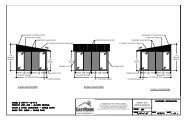
7’ X 10’ X 6’ SHELTER 7’ X 16’ X 6’ SHELTER<br />
12’ X 10’ X 6’ SHELTER 12’ X 16’ X 6’ SHELTER<br />
Our unique assembly process quickly transforms the individual pieces into a finished structure that will give<br />
you a lifetime of service. Great care has been taken to ensure complete satisfaction with your purchase. In<br />
the unlikely event that there are any missing or damaged parts, or if you simply need technical assistance,<br />
please call our Toll Free Hotline at 1-800-900-7222 and your questions will be addressed promptly. Thank you<br />
for choosing the VersaTube Building System.<br />
REV 3-3-06<br />
FOR MODEL NUMBERS:<br />
UC-079006, UC-0713506, UC-129006, UC-1213506<br />
PAGE 1
SAFETY AND HAZARD INSTRUCTIONS<br />
CAUTION:<br />
Read the following safety warnings and all instructions in their entirety prior to installation. If you have<br />
questions or are missing any parts, contact Mid-South Metal Products, Inc. (dba VersaTube Building<br />
Systems) Customer Service at 1-800-900-7222 before proceeding.<br />
WARNING:<br />
Metal parts may get hot when exposed to high heat or direct sunlight. Avoid contact with skin and wear<br />
protective gloves and clothing to prevent the possibility of burns.<br />
WARNING:<br />
Do not stand or walk on the structure. It is not designed to support human weight or the storage of<br />
materials on the roof. Collapse of the structure may cause serious injury due to weight of components.<br />
WARNING:<br />
Avoid installation on windy days as wind may create hazards during the installation process. Wind may<br />
blow material or cause partially installed components to collapse prior to being secured or fully installed.<br />
The weight of the components or structure may cause serious injury if it should collapse.<br />
WARNING:<br />
Metal conducts electricity and electrical shock hazards exist since the structure is made of metal. During<br />
installation or storage, keep the structure and all components away from electrical sources. Make sure that<br />
your selected location is away from power lines, underground cables, and any other source of electrical<br />
power. Serious injury or even death may occur if contact is made with electrical current.<br />
WARNING:<br />
If the structure is moved once it has been installed, be certain to inspect all components and conditions<br />
and follow each and every step of these instructions to make certain that the structure is securely<br />
anchored, properly installed, and aligned. Failure to follow these steps could lead to collapse of the<br />
structure and may result in serious risk of injury.<br />
WARNING:<br />
Be careful of the sharp edges which may cause cuts or lacerations. Wear protective work gloves and<br />
suitable clothing for protection and always take care when handling metal parts.<br />
WARNING:<br />
Always wear safety glasses or goggles when installing self-drilling screws.<br />
PAGE 2
PARTS LIST<br />
PARTS FOR 7’ X 10’ X 6’ SHELTER & 7’ X 16’ X 6’ SHELTER PART NO.<br />
STARTER BASE RAIL (2) 741-4045<br />
BASE EXTENSION (2) FOR 10’ SHELTER, (4) FOR 16’ SHELTER 741-7050<br />
SIDE POST (6) FOR 10’ SHELTER, (8) FOR 16’ SHELTER 741-5000<br />
PEAK: (3) FOR 10’ SHELTER, (4) FOR 16’ SHELTER 741-6070<br />
10’ SHEET METAL PANEL: (3) FOR 10’ SHELTER -<br />
16’ SHEET METAL PANEL: (3) FOR 16’ SHELTER -<br />
REBAR ANCHORS (6) FOR 10’ SHELTER, (8) FOR 16’ SHELTER ANC-24<br />
#12 X 3/4” SELF-DRILLING SCREWS: (40) FOR 10’ SHELTER, (70) FOR 16’ SHELTER 71-9999A, 71-9999<br />
#12 X 1” PAINTED, SELF-DRILLING SCREWS (120) 71-9999-W120<br />
VINYL TRIM: (45’) FOR 10’ SHELTER, (55’) FOR 15’ SHELTER 9901-VTW<br />
PARTS FOR 12’ X 10’ X 6’ SHELTER & 12’ X 16’ X 6’ SHELTER PART NO.<br />
STARTER BASE RAIL (2) 741-4045<br />
BASE EXTENSION (2) FOR 10’ SHELTER, (4) FOR 15’ SHELTER 741-7050<br />
SIDE POST (6) FOR 10’ SHELTER, (8) FOR 15’ SHELTER 741-5000<br />
PEAK (3) FOR 10’ SHELTER, (4) FOR 15’ SHELTER 741-6000<br />
10’ SHEET METAL PANEL (5) FOR 10’ SHELTER -<br />
16’ SHEET METAL PANEL (5) FOR 16’ SHELTER -<br />
REBAR ANCHORS (6) FOR 10’ SHELTER, (8) FOR 15’ SHELTER ANC-24<br />
#12 X 3/4” SELF-DRILLING SCREWS (70) FOR 10’ AND 16’ SHELTER 71-9999<br />
#12 X 1” PAINTED, SELF-DRILLING SCREWS (120) 71-9999-W120<br />
VINYL TRIM (60’) FOR 12’ X 10’ SHELTER, (72’) FOR 12’ X 16’ SHELTER 9901-VTW<br />
PAGE 3
ATTENTION:<br />
IT IS IMPORTANT THAT YOU READ THE FOLLOWING NOTE<br />
BEFORE STARTING THE ASSEMBLY OF YOUR SHELTER<br />
NOTE:<br />
If during the installation process you have difficulty fitting frame components together, use an<br />
adjustable wrench to open the end of the receiving tube as shown below. Close wrench down<br />
around bent portion of tube and bend wall outward. It may also be helpful to hit the center of the<br />
swage at the end of the tube to create more of a lead.<br />
Torque Setting<br />
Cordless (14 or 18 volt)<br />
Or Electric Screw Gun<br />
With 5/16" Socket Drive<br />
Safety Goggles<br />
Or glasses<br />
Work Gloves<br />
Pencil/Marker<br />
And Felt Marker<br />
Tape Measure<br />
Hammer<br />
What you’ll need<br />
Level<br />
Items you may need<br />
Masonry<br />
Drill Bit<br />
1/2” x 8”<br />
Drill depth<br />
Wrench, 3/4” & 1/2”<br />
Vise grip or other<br />
quick clamp<br />
STRIKE WITH HAMMER<br />
Adjustable wrench<br />
2 Step Ladders<br />
Shovel or<br />
Post Hole<br />
Digger<br />
Hammer<br />
Drill<br />
Chalk Line and<br />
Mason Line or<br />
Nylon String<br />
PAGE 4
SITE PREPARATION FOR <strong>ATV</strong> SPORT SHELTER<br />
The Versatube shelter frame is designed to be placed on a foundation that is level side-to-side and sloped about 1” front-<br />
to-back or back-to-front. That foundation can be: prepared ground (leveled and re-compacted), a concrete<br />
footing, or a concrete mono slab with built-in footing. It is important that you create one of these conditions prior to<br />
your carport or building installation. We recommend that you check with your local building official prior to starting your<br />
project to find out what is acceptable for foundations and anchoring in your county. If you extend the shelter site about 3<br />
or 4 feet on all sides, it will make it easier to position ladders for sheet metal installation.<br />
SLAB WITH FOOTING OR FOOTINGS ALONE<br />
If you will be pouring a slab for your shelter, the slab should be 4” thick and have a footing down both sides. The footing<br />
should be 10” wide x 8” deep with a 45° blend between the slab and the footing. The slab should have a front-to-back or<br />
back-to-front slope of about 1”. One run of #5 rebar mid-depth is recommended in the footing. Check with your local<br />
building official for details and requirements in your county. The concrete should be 2500 to 3000 PSI.<br />
The outside dimensions of the slab should be at least 4” larger than your frame dimensions. The slab should be at least<br />
7’-4” wide x 10’ long for a 7’ x 10’ shelter and 7’-4” wide x 15’ long for a 7’ x 15’ shelter. Make the slab 12’-4” wide and 10’<br />
long for a 12’ x 10’ shelter and 12’-4” wide x 15’ long foe a 12’ x 15’ shelter. This will allow the center of your anchor bolts<br />
to be 3” from the edge of the slab.<br />
FOOTINGS: Footings alone should be 10” wide and 8” deep and can be positioned so the base rails are centered in the<br />
footing if you will be using wedge anchor bolts to anchor the base rails. The outside dimension of the footing will be the<br />
shelter width plus 8”. Footings should be at least 3” longer than your frame. Footings should also slope 1” front-to-back or<br />
back-to-front to allow water that might gather in horizontal ribs to flow over roof lap joints and off the roof.<br />
4” SLAB WITH THICKENED SIDE EDGES<br />
4”<br />
#5 REBAR<br />
CONT.<br />
45˚<br />
#5 REBAR<br />
CONT.<br />
21/2”<br />
10”<br />
21/2”<br />
10”<br />
1/2” X 5 1/2”<br />
CONCRETE WEDGE<br />
ANCHOR<br />
10” X 8” FOOTING (BOTH SIDES OF SHELTER)<br />
3”<br />
8”<br />
2”<br />
8”<br />
1/2” X 5 1/2”<br />
CONCRETE WEDGE<br />
ANCHOR<br />
Frame Width + 4”<br />
10” Footing<br />
SLAB WITH FOOTING<br />
Frame + 3”<br />
PAGE 5
FRAME ASSEMBLY FOR 7’ WIDE SHELTER FRAMES: 7’ X 10’ (3 frame sections)<br />
AND 7’ X 16’ (4 frame sections)<br />
STEP 1: BASE RAIL ASSEMBLY<br />
There are two runs of base rails. Each run of base rails has a starter base rail (A) with two vertical insert pins and base<br />
extensions (B) with one vertical insert pin. 10’ frames have 1 extension and 16’ frames have 2 extensions. Insert one base<br />
extension into the starter base rail and then the other base extension into the first extension. Set the overall length dimension<br />
from the end of the starter base rail (A) to the end of the second base extension/extensions at 9’-2” for 10’ shelter or 13’-8”<br />
for 16’ shelter. Now, fasten the joints on top with two #12 x 3/4” self-drilling screws. Repeat this assembly for the other run of<br />
base rails.<br />
STEP 2: ROOF/WALL FRAME ASSEMBLY<br />
On the ground, assemble two side posts (C) and one peak (D) measure across the frame assembly at the top, just below the<br />
bends and at the bottom an set the frame width at 7’. Try to keep the joints on both sides of the peak equal. With the<br />
dimension set at 7’, attach the frame joints with two #12 x 3/4” self-drilling screws in each joint. Repeat this assembly for the<br />
remaining frame sections.<br />
STEP 3: ATTACHING THE ROOF/WALL FRAME SECTIONS TO THE BASE RAILS.<br />
Place the base rails in the location that you have prepared. Set the front of the base rail assemblies even and 7’ apart outside<br />
to outside. Now, set the back dimension 7’ apart.<br />
Set one roof/wall frame assembly on the vertical insert pins at the back of the carport. You may want to face the joint assembly<br />
screws to the back for a better appearance. Now, install the other two or three frame assemblies. Attach the side posts to<br />
the base rail insert pins with two #12 x 3/4” self-drilling screws on the back side of the assembly.<br />
7’<br />
7’<br />
BASE RAIL JOINT SIDE POST TO BASE<br />
RAIL JOINT<br />
A<br />
B<br />
D<br />
STARTER BASE RAIL<br />
C<br />
RAFTER TO SIDE<br />
POST OR PEAK JOINT<br />
#12 X 3/4” SELF-DRILLING<br />
SCREW<br />
BASE EXTENSIONS<br />
PAGE 6
FRAME ASSEMBLY FOR 12’ WIDE SHELTER FRAMES: 12’ X 10’ (3 frame sections)<br />
AND 12’ X 16’ (4 frame sections)<br />
STEP 1: BASE RAIL ASSEMBLY<br />
There are two runs of base rails. Each run of base rails has a starter base rail (A) with two vertical insert pins and base<br />
extensions (B) with one vertical insert pin. 10’ frames have 1 extension and 16’ frames have 2 extensions. Insert one base<br />
extension into the starter base rail and then the other base extension into the first extension. Set the overall length dimension<br />
from the end of the starter base rail (A) to the end of the second base extension/extensions at 9’-2” for 10’ shelter or 13’-8”<br />
for 16’ shelter. Now, fasten the joints on top with two #12 x 3/4” self-drilling screws. Repeat this assembly for the other run of<br />
base rails.<br />
STEP 2: ROOF/WALL FRAME ASSEMBLY<br />
On the ground, assemble two side posts (C) and one peak (D) and two rafters (E). Measure across the frame assembly at<br />
the top, just below the bends and at the bottom an set the frame width at 12’. Try to keep the joints on both sides of the peak<br />
equal. With the dimension set at 12’, attach the frame joints with two #12 x 3/4” self-drilling screws in each joint. Repeat this<br />
assembly for the remaining frame sections.<br />
STEP 3: ATTACHING THE ROOF/WALL FRAME SECTIONS TO THE BASE RAILS.<br />
Place the base rails in the location that you have prepared. Set the front of the base rail assemblies even and 12’ apart outside<br />
to outside. Now, set the back dimension 12’ apart.<br />
Set one roof/wall frame assembly on the vertical insert pins at the back of the carport. You may want to face the joint assembly<br />
screws to the back for a better appearance. Now, install the other two or three frame assemblies. Attach the side posts to<br />
the base rail insert pins with two #12 x 3/4” self-drilling screws on the back side of the assembly.<br />
12’ x 16’ frame shown.<br />
12’ x 10’ frame has 3<br />
frame sections.<br />
12’<br />
12’<br />
BASE RAIL JOINT SIDE POST TO BASE<br />
RAIL JOINT<br />
A<br />
D<br />
B<br />
E<br />
C<br />
#12 X 3/4” SELF-DRILLING<br />
SCREW<br />
RAFTER TO SIDE<br />
POST OR PEAK JOINT<br />
PAGE 7
ANCHORING TO GROUND WITH CONCRETE PIERS<br />
DIGGING HOLES FOR CONCRETE<br />
Mark the locations of the rails and the anchor holes on the ground. Move the shelter to one side and dig holes at each<br />
anchor point for concrete. You may want to rent a gas-powered post hole digger with an 8” diameter auger for this job.<br />
HOLE SIZE:<br />
Dig a 8” diameter hole 18” deep at each anchor hole in base rails (8 total).<br />
ANCHORING<br />
Move the base rails back into position over the holes. Re-measure to make sure the rails are in the proper location.<br />
( 12’ apart outside to outside). Measure diagonals to square frame. The diagonal measurements should be equal.<br />
Now drop or drive a Versatube 30” re-bar ground anchor into each anchor hole.<br />
Mix up concrete and pour into holes up to ground level. You may want to rent a mixer for this job. Before the concrete<br />
sets, re-check all your dimensions to make sure the frame is square and has the proper width.<br />
Let the concrete cure overnight before installing the sheet metal panels on the roof.<br />
Note: If you do not have time to wait over night for the concrete to cure, you can install the sheet metal panels before you<br />
anchor the shelter. IMPORTANT: You must level and square the frame before you attempt to install sheet metal. Failure<br />
to support the frame in a square and level condition will result in crooked sheet metal and possible leaks when frame is<br />
shifted for anchoring later.<br />
BASE RAIL<br />
CONCRETE<br />
VERSATUBE<br />
RE-BAR GROUND ANCHOR<br />
ANCHORING TO CONCRETE SLAB OR FOOTING WITH 1/2” X 5 1/2” CONCRETE WEDGE ANCHORS<br />
(NOT INCLUDED)<br />
Place the assembled shelter frame on the concrete slab or footings and re-measure to be sure that the base rails are 12’<br />
outside to outside at the front and back of the frame. Measure the diagonals to square the frame. Diagonal measurements<br />
should be equal.<br />
To drill the anchor holes, you will need a hammer drill and a 1/2” concrete drill bit long enough to go through the 2” base<br />
rail and 3” into the concrete. Hold the base rail in place with your foot, insert the drill bit through the anchor hole in the<br />
base rail and drill a hole 3” into the concrete. The base rail is 2” thick, so the total depth from the top of the base rail will<br />
be 5”.<br />
Place a flat washer onto the anchor bolt and screw on a hex nut until about 2 threads are exposed above the nut. Now,<br />
place the bolt in the hole and tap it down with a hammer until the nut and washer touch the top of the base rail. Use a 3/4”<br />
wrench to tighten the nut. Tighten the nut until it is snug. Do not crush the base rail tube.<br />
FLAT WASHER<br />
AND NUT<br />
BASE RAIL<br />
DRILL A 1/2 X 3”<br />
DEEP HOLE IN<br />
CONCRETE<br />
1/2” X 5 1/2” WEDGE ANCHOR BOLT<br />
(INSTALL ONE IN EACH BASE RAIL<br />
ANCHOR HOLE)<br />
SLAB OR FOOTING<br />
PAGE 8
INSTALLING SHEET METAL PANELS ON 7’ X 10’ X 6’ SHELTER<br />
INSTALLING THE FIRST PANEL (10’ PANEL)<br />
Before you place the first panel on the roof, put a mark on all four peak tubes 3 1/2” up from the top end of the side post as<br />
shown in detail (A) below.<br />
Each panel has an under lap and an overlap edge. The under lap edge has a small flange at the edge. The overlap edge is<br />
just a partial rib with no flange. (See illustration below).<br />
Place the first panel on the roof in the center of the frame as shown with the flanged of the under lap edge of the panel lined<br />
up with the marks that you put on the peak tubes. This will center the first panel on the frame. The ends of the panel should<br />
overhang the ends of the frame 5 1/4”. Fasten the panel to the frame with #12 x 1” painted, self-drilling screws with sealing<br />
washers. Place screws in the pattern indicated in the in the illustration below. Do not install screws next the center rib of the<br />
panel. Also, do not install screws above the lower edge ribs of the panel at this time. You will be sliding the lower panels under<br />
the first panel.<br />
OVERLAP EDGE<br />
UNDER LAP EDGE<br />
5 1/4”<br />
LINE PANEL UP<br />
WITH MARKS<br />
INSTALLING THE LOWER PANELS ON THE 7’ X 10’ SHELTERS<br />
DETAIL (A)<br />
MARK ON<br />
ALL PEAKS<br />
3 1/2”<br />
SIDE POST<br />
PLACE SCREWS ABOUT 1” FROM RIB<br />
Note: On one side of the roof you will be sliding an under lap edge under an under lap edge and on the other side of the roof<br />
you will be sliding an under lap edge under an overlap edge. Start on ether side of the roof to install one of the lower panels.<br />
Lift the edge of the first panel and slip the under lap edge of the lower panel under the edge of panel (1). Line up the end of<br />
the panel with the end of panel (1) and install screws in the pattern indicated. Note that there are no screws in the bends of<br />
the frame. The frame bends have channels that would cause the roof panels to dimple if screws were installed in the bends.<br />
Install screws above the lower ribs of panel 1 at this time. Repeat assembly for lower panel on other side of roof.<br />
UNDER LAP RIB<br />
UNDER OVERLAP<br />
RIB<br />
UNDER LAP RIB TO THE<br />
TOP SIDE OF LOWER<br />
PANELS<br />
NO SCREWS IN<br />
SIDE POST BEND<br />
SEE INSTALLING<br />
VINYL EDGE TRIM<br />
ON LAST PAGE<br />
PAGE 9
INSTALLING SHEET METAL PANELS ON 7’ X 16’ X 6’ SHELTER<br />
INSTALLING THE FIRST PANEL (16’ PANEL)<br />
Before you place the first panel on the roof, put a mark on all four peak tubes 3 1/2” up from the top end of the side post as<br />
shown in detail (A) below.<br />
Each panel has an under lap and an overlap edge. The under lap edge has a small flange at the edge. The overlap edge is<br />
just a partial rib with no flange. (See illustration below).<br />
Place the first panel (16’ long panel) on the roof in the center of the frame at the lower end of the carport (The end with the<br />
base extensions, not the starter rail) as shown with the flanged of the under lap edge of the panel lined up with the marks<br />
that you put on the peak tubes. This will center the first panel on the frame. The end of the panel should overhang the end of<br />
the frame 14 1/4”. Fasten the panel to the frame with #12 x 1” painted, self-drilling screws with sealing washers. Place<br />
screws in the pattern indicated in the in the illustration below. Do not install screws above the lower edge ribs of the panel at<br />
this time. You will be sliding the lower panels under the first panel on both sides of the shelter.<br />
MARK ON<br />
ALL PEAKS<br />
OVERLAP EDGE<br />
SIDE POST<br />
3 1/2”<br />
DETAIL (A)<br />
FLUSH<br />
UNDER LAP EDGE<br />
14 1/4” OVERHANG<br />
3 1/2”<br />
LINE EDGE OF<br />
PANEL WITH<br />
MARK<br />
PAGE 10
INSTALLING THE LOWER PANELS ON THE 7’ X 16’ SHELTER (panels 3 and 4)<br />
Note: On one side of the roof you will be sliding an under lap edge under an under lap edge and on the other side of the roof<br />
you will be sliding an under lap edge under an overlap edge. Lift the edge of panel 1 and slip the under lap edge of panel 2<br />
under the edge of panel 1. Line up the end of the panel with the end of panel (1).<br />
Fasten the panel to the frame with screws in the pattern indicated below. Note that there are no screws in the bend portions<br />
of the side posts. The frame bends have channels that would cause the roof panels to dimple if screws were installed in the<br />
bends.<br />
Install screws above the lower ribs of panel 1 at this time. Repeat this assembly for lower panel 3 on the other side of the<br />
roof.<br />
UNDER LAP RIB TO THE TOP SIDE OF LOWER PANELS<br />
SEE INSTALLING VINYL EDGE TRIM ON LAST PAGE<br />
PANEL 1<br />
PANEL 2<br />
PAGE 11
INSTALLING SHEET METAL PANELS ON 12’ X 10’ X 6’ SHELTER<br />
INSTALLING THE FIRST PANEL (10’ PANEL)<br />
Before you place the first panel on the roof, put a mark on all four peak tubes 17 1/8” up from the end as shown in detail (A)<br />
below.<br />
Each panel has an under lap and an overlap edge. The under lap edge has a small flange at the edge. The overlap edge is<br />
just a partial rib with no flange. (See illustration below).<br />
Place the first panel on the roof in the center of the frame as shown with the flanged of the under lap edge of the panel lined<br />
up with the marks that you put on the peak tubes. This will center the first panel on the frame. The ends of the panel should<br />
overhang the ends of the frame 5 1/4”. Fasten the panel to the frame with #12 x 1” painted, self-drilling screws with sealing<br />
washers. Place screws in the pattern indicated in the in the illustration below. Do not install screws next the center rib of the<br />
panel. Also, do not install screws above the lower edge ribs of the panel at this time. You will be sliding the lower panels under<br />
the first panel.<br />
OVERLAP EDGE<br />
UNDER LAP EDGE<br />
UNDER LAP RIB<br />
UNDER OVERLAP<br />
RIB<br />
INSTALLING LOWER PANELS<br />
Lift the lower edge of the upper panel and<br />
slide the under lap edge of the lower panel<br />
under of the edge of the upper panel. Line up<br />
the ends of the panels and install screws in<br />
the pattern indicated in the illustration to the<br />
right. Note that no screws are placed in the<br />
side post bends. The bends have channels<br />
and would cause screws to dimple the panels.<br />
Repeat on other side of roof.<br />
SEE INSTALLING<br />
VINYL EDGE TRIM<br />
ON LAST PAGE<br />
5 1/4”<br />
UNDER LAP RIB TO THE TOP<br />
SIDE OF LOWER PANELS<br />
PANEL 1<br />
LINE EDGE<br />
OF PANEL<br />
WITH MARK<br />
MARK ON<br />
ALL PEAKS<br />
DETAIL (A)<br />
17 1/8”<br />
SIDE POST<br />
PANEL 2<br />
PANEL 3<br />
NO SCREWS IN<br />
SIDE POST BEND<br />
UNDER LAP RIB<br />
UNDER OVERLAP<br />
RIB<br />
PAGE 12
INSTALLING SHEET METAL PANELS ON 12’ X 16’ X 6’ SHELTER<br />
INSTALLING THE FIRST PANEL (16’ PANEL)<br />
Before you place the first panel on the roof, put a mark on all four peak tubes 17 1/8” up from the end as shown in detail (A)<br />
below.<br />
Each panel has an under lap and an overlap edge. The under lap edge has a small flange at the edge. The overlap edge is<br />
just a partial rib with no flange. (See illustration below).<br />
Place the first panel (16’ long panel) on the roof in the center of the frame as shown with the flanged of the under lap edge of<br />
the panel lined up with the marks that you put on the peak tubes. This will center the first panel on the frame. The ends of the<br />
panel should overhang the ends of the frame 14 1/4”. Fasten the panel to the frame with #12 x 1” painted, self-drilling screws<br />
with sealing washers. Place screws in the pattern indicated in the in the illustration below. Do not install screws above the<br />
lower edge ribs of the panel at this time. You will be sliding the lower panels under the first panel.<br />
UNDER LAP EDGE<br />
14 1/4”<br />
OVERLAP EDGE<br />
LINE EDGES<br />
OF PANEL<br />
WITH MARKS<br />
MARK ON<br />
ALL PEAKS<br />
DETAIL (A)<br />
17 1/8”<br />
SIDE POST<br />
PAGE 13
INSTALLING ADDITIONAL PANELS ON THE 12’ X 16’ SHELTER (panels 2, 3, 4 & 5)<br />
Note: On one side of the roof you will be sliding an under lap edge under an under lap edge on panel (2) and on the other<br />
side of the roof you will be sliding an under lap edge under an overlap edge.<br />
Lift the edge of panel 1 and slip the under lap edge of panel 2 under the edge of panel 1. Line up the end of the panel (2)<br />
with the end of panel (1). Now, fasten the panel to the frame with screws in the pattern indicated below.<br />
Now, install panel (3) as you did panel (2). The lower portion of the panel will fold around the side post bends and be fastened<br />
of the side of the frame. Note that there are no screws in the bend portions of the side posts. The frame bends have<br />
channels that would cause the roof panels to dimple if screws were installed in the bends.<br />
Repeat this assembly for panels 4 & 5 on the other side of the shelter.<br />
PANEL 2<br />
UNDER LAP RIB TO<br />
THE TOP SIDE OF<br />
LOWER PANELS<br />
SEE INSTALLING<br />
VINYL EDGE TRIM<br />
ON LAST PAGE<br />
PANELS 4 & 5<br />
ON THIS SIDE<br />
PANEL 1<br />
NO SCREWS IN<br />
SIDE POST BEND<br />
PANEL 2<br />
PANEL 3<br />
PAGE 14
INSTALLING VINYL EDGE TRIM:<br />
Install vinyl edge trim on front, back and side edges of sheet metal panels. Start at one corner and push the trim securely<br />
over the sheet metal edge. Install the trim on the gable ends first starting at one corner, up along the gable and down to<br />
the other corner. Install vinyl edge trim on both side edges of the carport. Clip the trim flush with the edge of the trim on<br />
the gable ends. It may help to use a small hammer to fit trim over major ribs. Use your tin snips to cut the trim.<br />
VINYL TRIM, GABLE END VINYL TRIM, SIDE EDGE<br />
BUTT SIDE EDGE TRIM UP TO GABLE END TRIM<br />
PAGE 15