Pallet Jack - Menards
Pallet Jack - Menards
Pallet Jack - Menards

Create successful ePaper yourself
Turn your PDF publications into a flip-book with our unique Google optimized e-Paper software.
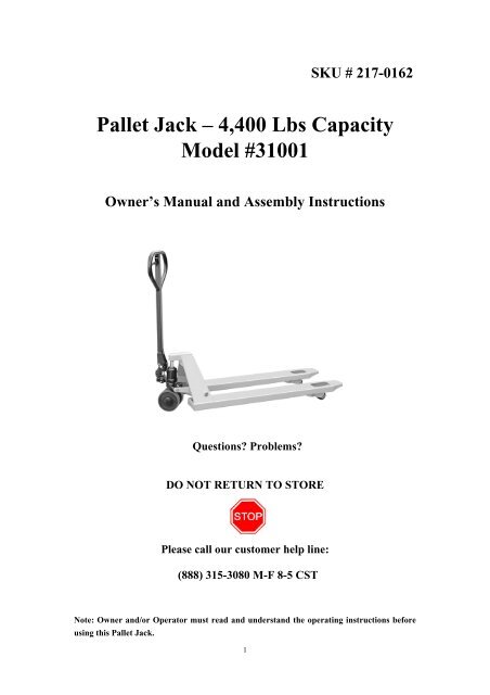
SKU # 217-0162<br />
<strong>Pallet</strong> <strong>Jack</strong> – 4,400 Lbs Capacity<br />
Model #31001<br />
Owner’s Manual and Assembly Instructions<br />
Questions? Problems?<br />
DO NOT RETURN TO STORE<br />
Please call our customer help line:<br />
(888) 315-3080 M-F 8-5 CST<br />
Note: Owner and/or Operator must read and understand the operating instructions before<br />
using this <strong>Pallet</strong> <strong>Jack</strong>.<br />
1
• Handle Assembly Instructions:<br />
1. Important note: The spring of the pallet jack is held in place with a pin (pin B). Do not<br />
remove this pin. Please follow instructions on when this pin should be removed.<br />
2. Pull out pin shaft (part 23). Please refer to Fig. 1.<br />
Fig. 1 Fig. 2<br />
3. Insert handle tube (part 89) into position A. Connect handle tube and the pump body (part<br />
31) via the pin shaft (part 23). Please note the hole in the center of the pin shaft. The chain<br />
(part 10) from the handle will need to be inserted through this hole in step 5. Make sure<br />
that this pin shaft is aligned into the groove of the pump body. Please refer to Fig. 1 and<br />
parts diagram.<br />
4. Insert cotter pin (part 24) through the other end of the pin shaft (part 23).<br />
5. Position chain (part 10) of the handle tube (part 89) over the pressure roller (part 13) and<br />
through the hole in the center of the pin shaft (part 23). Please refer to Fig. 2 and picture<br />
below.<br />
2
Fig. 3 Fig. 4<br />
6. The screw and nut (part 11) at the end of the chain (part 10) should be positioned securely<br />
into the slot of the lever plate (part 52). You may need to manually adjust the lever plate<br />
so that the screw and nut fit into the slot. Tighten the screw once in place. Please refer to<br />
Fig. 2 and Fig. 4<br />
7. Lower the handle to a horizontal position. Pull out pin B. This will engage the spring (part<br />
20). Store pin B in a safe place so that it can be used for future handle replacements. This<br />
step should complete the assembly. Please refer to Fig. 3.<br />
• Final steps before use:<br />
1. After assembly is complete, test the trigger at different positions to make sure the<br />
lowering, neutral and raising operations are fully functional. Please refer to Fig. 5<br />
2. For adjustments to the pallet jack, please refer to the adjustment screw (part 54) seen in<br />
Fig. 4. In the case where the body of the pallet jack lowers automatically after it has been<br />
raised, turn the adjustment screw (part 54) in a counterclockwise direction until desired<br />
action is met. If the body of the pallet jack is unable to be lowered, turn the adjustment<br />
screw (part 54) in a clockwise direction until the pallet jack is able to be lowered<br />
manually.<br />
3. The hex nut (part 53) and adjustment screw (part 54) function as a lock so they will<br />
remain securely locked after any adjustments have been made.<br />
4. The weight capacity of this pallet jack is 4,400 lbs. Please do not exceed the weight<br />
limitation.<br />
Fig. 5<br />
3
WARNING:<br />
• Lower the pallet jack gently. Hasty lowering of the jack may cause damage to the jack<br />
and the cargo.<br />
• Do not overload the pallet jack.<br />
• Do not exceed the weight limitation.<br />
• The center of gravity of the goods should be positioned in the middle of the 2 forks.<br />
Unbalanced loads may cause the pallet jack to overturn.<br />
• Do not use the pallet jack to transport loose or unstable cargo.<br />
• Set the forks to the lowest position when not in use.<br />
• Do not place cargo on the pallet jack for extended periods of time.<br />
• Do not stand on the forks.<br />
• Do not operate the pallet jack on a slope or an uneven surface.<br />
• Do not try to repair the pallet jack without proper training.<br />
4
Limited One-Year Warranty<br />
Great Lakes Tool Mfg., Inc. warrants its products to be free of defects from workmanship and<br />
materials for a period of one year from date of original purchase. We will repair or replace, at our<br />
option, any product covered by this warranty that after inspection is found to be defective in<br />
materials or workmanship during the warranty period.<br />
This warranty does not apply if the product has been misused, abused, subject to an accident,<br />
altered, repaired by others not authorized and is used in commercial or rental applications. Normal<br />
wear and tear is also not covered by this warranty.<br />
To take advantage of this warranty, please contact us at 1-888-315-3080. You will need proof of<br />
purchase and be asked to ship the product back to us freight prepaid.<br />
Under no circumstances shall Great Lakes Tool Mfg., Inc be liable for any indirect, incidental or<br />
consequential damages from the sale or use of this product. Some states do not allow the exclusion<br />
or limitation of incidental or consequential damages. Some states do not allow limitations on the<br />
length of an implied warranty. This warranty provides you with specific legal rights and you may<br />
have other rights that vary from state to state.<br />
5