eThrough the Wall Exhaust Fan - Menards
eThrough the Wall Exhaust Fan - Menards
eThrough the Wall Exhaust Fan - Menards

You also want an ePaper? Increase the reach of your titles
YUMPU automatically turns print PDFs into web optimized ePapers that Google loves.
e Through<br />
210575001 Rev. A 1-08<br />
aWF180<br />
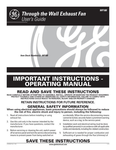
<strong>the</strong> <strong>Wall</strong> <strong>Exhaust</strong> <strong>Fan</strong><br />
User’s Guide<br />
Item Stock Number(s): WF180<br />
IMPORTANT INSTRUCTIONS -<br />
OPERATING MANUAL<br />
READ AND SAVE THESE INSTRUCTIONS<br />
READ CAREFULLY BEFORE ATTEMPTING TO ASSEMBLE, INSTALL, OPERATE OR MAINTAIN THE PRODUCT DESCRIBED.<br />
PROTECT YOURSELF AND OTHERS BY OBSERVING ALL SAFETY INFORMATION. FAILURE TO COMPLY WITH<br />
INSTRUCTIONS COULD RESULT IN PERSONAL INJURY AND/OR PROPERTY DAMAGE!<br />
RETAIN INSTRUCTIONS FOR FUTURE REFERENCE.<br />
GENERAL SAFETY INFORMATION<br />
When using electrical appliances, basic precautions should always be followed to reduce<br />
<strong>the</strong> risk of fire, electric shock and injury to person, including <strong>the</strong> following:<br />
1. Read all instructions before installing or using<br />
exhaust fan.<br />
2. Use this unit only in <strong>the</strong> manner intended by <strong>the</strong><br />
manufacturer. If you have questions, contact <strong>the</strong><br />
manufacturer.<br />
3. Before servicing or cleaning <strong>the</strong> unit, switch power<br />
off at service panel and lock <strong>the</strong> service disconnecting<br />
means to prevent power from being switched on<br />
accidentally. When <strong>the</strong> service disconnecting means<br />
cannot be locked, securely fasten a prominent warning<br />
device, such as a tag, to <strong>the</strong> service panel.<br />
4. Installation work and electrical wiring must be done<br />
by qualified person(s) in accordance with all applicable<br />
codes and standards, including fire-related construction.<br />
5. Sufficient air is needed for proper combustion and<br />
exhausting of gases through <strong>the</strong> flue (chimney) of<br />
SAVE THESE INSTRUCTIONS<br />
www.geelectrical.com<br />
1 of 8
GENERAL SAFETY INFORMATION<br />
(Continued)<br />
fuel burning equipment to prevent back drafting. Follow<br />
<strong>the</strong> heating equipment manufacturer’s guideline and<br />
safety standards such as those published by <strong>the</strong> National<br />
Fire Protection Association (NFPA) and <strong>the</strong> American<br />
Society for Heating, Refrigeration, and Air Conditioning<br />
Engineers (ASHRAE), and <strong>the</strong> local code authorities.<br />
CAUTION: FOR GENERAL VENTILATING USE<br />
ONLY. DO NOT USE TO EXHAUST HAZARDOUS OR<br />
EXPLOSIVE MATERIALS AND VAPORS.<br />
6. When cutting or drilling into wall or ceiling, do not<br />
damage electrical wiring and o<strong>the</strong>r hidden utilities.<br />
7. Ducted fans must always be vented to <strong>the</strong> outdoors.<br />
8. This unit must be grounded.<br />
9. To avoid motor bearing damage and noisy and/or<br />
unbalanced impellers, keep drywall spray, construction<br />
dust, etc. off power unit.<br />
WARNING: TO REDUCE THE RISK OF FIRE,<br />
ELECTRIC SHOCK, DO NOT USE THIS FAN WITH ANY<br />
SOLID-STATE SPEED CONTROL DEVICE.<br />
10. NEVER place a switch where it can be reached from<br />
a tub or shower.<br />
WARNING: DO NOT USE IN KITCHENS<br />
INSTALLATION INSTRUCTIONS<br />
CAUTION: MAKE SURE POWER IS SWITCHED OFF<br />
AT SERVICE PANEL BEFORE STARTING INSTALLATION.<br />
SECTION 1<br />
Preparing <strong>the</strong> <strong>Exhaust</strong> <strong>Fan</strong><br />
1. Unpack fan from <strong>the</strong> carton and confirm that all<br />
pieces are present. In addition to <strong>the</strong> exhaust fan<br />
you should have:<br />
1 - Grill<br />
1 - Grill Knob<br />
1 - Wiring Compartment and screws<br />
1 - Motor<br />
1 - Housing<br />
1 - Instruction/Safety Sheet<br />
NOTE: This fan is designed to mount between exterior<br />
walls 4-1/2" to 9-1/2" in thickness.<br />
2. Remove <strong>the</strong> motor bracket assembly from <strong>the</strong> fan<br />
housing by loosening <strong>the</strong> two screws which secure<br />
<strong>the</strong> bracket in place (Figure 1).<br />
210575001 Rev. A 1-08<br />
Figure 1<br />
3. Slide <strong>the</strong> inner housing out from <strong>the</strong> outer housing<br />
and set aside in a safe place (Figure 2).<br />
Outer<br />
Housing<br />
Figure 2<br />
www.geelectrical.com<br />
Screws<br />
SECTION 2<br />
Mounting <strong>the</strong> Housing<br />
1. From inside <strong>the</strong> house, choose <strong>the</strong> best location to<br />
mount <strong>the</strong> housing on an exterior wall. Make sure to<br />
locate <strong>the</strong> housing where <strong>the</strong>re are no studs,<br />
electrical/mechanical utilities, or any o<strong>the</strong>r obstructions.<br />
2. Once you have selected <strong>the</strong> best location from inside<br />
<strong>the</strong> house, transfer <strong>the</strong> location to <strong>the</strong> exterior of <strong>the</strong><br />
house and confirm that <strong>the</strong>re are no obstructions in <strong>the</strong><br />
location and <strong>the</strong> fan has proper clearance to operate.<br />
3. Once <strong>the</strong> installation location has been confirmed,<br />
cut a 8-1/4" diameter hole in <strong>the</strong> interior wall where<br />
<strong>the</strong> fan is to be located (Figure 3).<br />
Exterior<br />
<strong>Wall</strong><br />
Figure 3<br />
Interior<br />
<strong>Wall</strong><br />
Hole<br />
Exterior<br />
<strong>Wall</strong><br />
Inner<br />
Housing<br />
Interior<br />
<strong>Wall</strong><br />
4. Drill a small hole through to <strong>the</strong> outside in <strong>the</strong> center<br />
of <strong>the</strong> 8-1/4" diameter hole, so you can properly locate<br />
<strong>the</strong> exterior housing (Figure 3).<br />
5. On <strong>the</strong> siding of <strong>the</strong> outside wall, layout a 14-1/2" x 14-<br />
1/2" square using <strong>the</strong> small hole drilled in Step 4 as <strong>the</strong><br />
center point and cut out <strong>the</strong> square hole (Figure 4).<br />
2 of 8
Figure 4<br />
CAUTION: ONLY CUT THE EXTERIOR WALL SIDING.<br />
DO NOT CUT INTO THE SHEATHING (PLYWOOD)<br />
UNDERNEATH.<br />
6. Once <strong>the</strong> siding is cut, nail down all <strong>the</strong> loose ends<br />
of <strong>the</strong> siding (Figure 4).<br />
7. In <strong>the</strong> center of <strong>the</strong> 14-1/2" square cut in step 5, mark<br />
and cut a 8-1/4" diameter hole through <strong>the</strong> wall<br />
sheathing (Figure 5).<br />
8-1/4"<br />
Figure 5<br />
8. Install 1" x 2" casing strips (not included) for support<br />
on <strong>the</strong> edges of <strong>the</strong> 14-1/2" square hole. Secure<br />
casing strips to plywood sheathing with screws or<br />
nails (not included) and seal where <strong>the</strong> strips meet<br />
<strong>the</strong> plywood with caulk (Figure 5).<br />
CAUTION: IF SHEATHING IS NOT PLYWOOD, YOU<br />
WILL HAVE TO ADD ADDITIONAL SUPPORT FOR THE<br />
INSTALLATION.<br />
9. If <strong>the</strong> wall is less than 8" thick, remove one or more<br />
of <strong>the</strong> electrical compartment clearance knockouts<br />
located on <strong>the</strong> housing (Figure 6).<br />
Figure 6<br />
210575001 Rev. A 1-08<br />
14-1/2" Nail<br />
Casing<br />
Strips<br />
Knockouts<br />
www.geelectrical.com<br />
10. On <strong>the</strong> interior flange of <strong>the</strong> housing, apply a<br />
generous amount of caulking and install <strong>the</strong> housing<br />
through <strong>the</strong> hole and onto <strong>the</strong> casing strips and<br />
secure in place using screws or nails (not included)<br />
through <strong>the</strong> predrilled holes on <strong>the</strong> four corners of<br />
<strong>the</strong> housing. Seal <strong>the</strong> flange where <strong>the</strong> housing<br />
meets <strong>the</strong> wall with caulk (Figure 7).<br />
Screws<br />
Figure 7<br />
SECTION 3<br />
Wiring<br />
CAUTION: MAKE SURE POWER IS SWITCHED OFF<br />
AT SERVICE PANEL BEFORE STARTING INSTALLATION.<br />
CAUTION: ALL ELECTRICAL CONNECTIONS MUST<br />
BE MADE IN ACCORDANCE WITH LOCAL CODES,<br />
ORDINANCES, OR NATIONAL ELECTRICAL CODE. IF YOU<br />
ARE UNFAMILIAR WITH METHODS OF INSTALLING<br />
ELECTRICAL WIRING, SECURE THE SERVICES OF A<br />
QUALIFIED ELECTRICIAN.<br />
1. Run wiring from an approved wall switch carrying<br />
<strong>the</strong> appropriate rating. One neutral (white), one<br />
ground (green or bare copper), and one hot (black).<br />
2. From inside <strong>the</strong> house, insert <strong>the</strong> inner housing into<br />
<strong>the</strong> outer housing until it is tight against <strong>the</strong> wall. Line<br />
up three holes at <strong>the</strong> end of <strong>the</strong> inner housing with<br />
three of <strong>the</strong> holes on <strong>the</strong> outer housing and secure in<br />
place with <strong>the</strong> three included 3/8" screws (Figure 8).<br />
Figure 8<br />
Holes<br />
Caulk<br />
Knockouts<br />
Inner<br />
Housing<br />
Electrical<br />
Opening<br />
NOTE: If you removed any of <strong>the</strong> electrical compartment<br />
clearance knockouts on <strong>the</strong> outer housing, make sure<br />
<strong>the</strong> electrical opening of <strong>the</strong> inner housing is aligned<br />
with <strong>the</strong>m.<br />
3 of 8
3. Pull <strong>the</strong> electrical wires through <strong>the</strong> electrical<br />
opening of <strong>the</strong> interior housing. Remove one of <strong>the</strong><br />
electrical knockouts of <strong>the</strong> wiring compartment and<br />
run wires through <strong>the</strong> opening making sure to leave<br />
enough wiring to make <strong>the</strong> connection to <strong>the</strong> fan’s<br />
receptacle. Secure wires to wiring compartment<br />
with an approved electrical connector (Figure 9).<br />
Electrical<br />
Opening<br />
Figure 9<br />
4. Connect <strong>the</strong> green or bare ground wire from <strong>the</strong><br />
house to <strong>the</strong> ground screw in <strong>the</strong> wire compartment.<br />
Connect <strong>the</strong> white wire from <strong>the</strong> house to <strong>the</strong> white<br />
wire from <strong>the</strong> receptacle. Connect <strong>the</strong> hot (black)<br />
wire from <strong>the</strong> wall switch to <strong>the</strong> black wire from <strong>the</strong><br />
receptacle (Figure 10). Use approved methods for<br />
all connections.<br />
Figure 10<br />
5. Insert <strong>the</strong> wire compartment into <strong>the</strong> electrical<br />
opening of <strong>the</strong> interior housing and line up holes of<br />
wire compartment and wire compartment cover with<br />
holes on <strong>the</strong> interior housing. Secure in place using<br />
<strong>the</strong> two included 1/2" screws (Figure 11).<br />
Figure 11<br />
210575001 Rev. A 1-08<br />
Wiring Compartment<br />
Wiring Compartment<br />
Cover<br />
Wiring Compartment<br />
Electrical Opening<br />
Knockouts<br />
www.geelectrical.com<br />
SECTION 4<br />
Completing <strong>the</strong> Installation<br />
1. Reinstall <strong>the</strong> fan’s motor bracket by sliding in place<br />
and tightening <strong>the</strong> screws. Rotate <strong>the</strong> blower wheel<br />
by hand to ensure it spins freely. Now plug <strong>the</strong> fan<br />
motor into <strong>the</strong> receptacle (Figure 1).<br />
2. Install grill by positioning over <strong>the</strong> inner housing and<br />
aligning <strong>the</strong> center hole on <strong>the</strong> grill with <strong>the</strong> hole on<br />
<strong>the</strong> motor bracket. Screw one side of <strong>the</strong> included<br />
grill bolt into <strong>the</strong> hole on <strong>the</strong> motor bracket and <strong>the</strong><br />
o<strong>the</strong>r side into <strong>the</strong> grill knob and turn to tighten until<br />
<strong>the</strong> grill is tightly fit against <strong>the</strong> wall. DO NOT OVER<br />
TIGHTEN (Figure 12).<br />
Figure 12<br />
Motor Bracket<br />
Hole<br />
3. Restore power and test your installation.<br />
SECTION 5<br />
Use and Care<br />
Grill<br />
Bolt<br />
Grill Knob<br />
CAUTION: MAKE SURE POWER IS SWITCHED<br />
OFF AT SERVICE PANEL BEFORE SERVICING THE UNIT.<br />
1. Cleaning <strong>the</strong> Grill: Remove grill and use a mild<br />
detergent, such as dishwashing liquid, and dry with<br />
a soft cloth. NEVER USE ANY ABRASIVE PADS OR<br />
SCOURING POWDERS. Completely dry grill before<br />
reinstalling. Refer to instructions in Section 4<br />
Completing <strong>the</strong> Installation, to reinstall grill.<br />
2. Cleaning <strong>the</strong> <strong>Fan</strong> Assembly: Wipe all parts with a<br />
dry cloth or gently vacuum <strong>the</strong> fan. NEVER IMMERSE<br />
ELECTRICAL PARTS IN WATER<br />
4 of 8
Trouble<br />
Troubleshooting Guide<br />
Probable Cause Suggested Remedy<br />
1. <strong>Fan</strong> does not operate when <strong>the</strong> switch is on. 1a. A fuse may be blown or a circuit tripped. 1a. Replace fuse or reset circuit breaker.<br />
1b. Connector plug from motor is not plugged in. 1b. Turn off power to unit. Remove Grill and plug motor into receptacle<br />
in housing. Restore power to unit.<br />
1c. Wiring is not connected properly. 1c. Turn off power to unit. Check that all wires are connected.<br />
1d. Motor has stopped operating. 1d. Replace motor.<br />
2. <strong>Fan</strong> is operating, but air moves slower than normal. 2. Obstruction in <strong>the</strong> outer housing. 2. Check for any obstructions where <strong>the</strong> fan exhausts to <strong>the</strong> outside.<br />
3. <strong>Fan</strong> is operating louder than normal. 3a. Motor is loose. 3a. Turn off power to unit. Remove grill and check that all screws are fully<br />
tightened. Restore power to unit.<br />
3b. Grill is loose 3b. Tighten grill knob.<br />
210575001 Rev. A 1-08 5 of 8<br />
www.geelectrical.com
WARRANTY<br />
WHAT IS COVERED?<br />
Full Five Year Parts Warranty from date of original proof of<br />
purchase. We will provide, free of charge, a replacement part<br />
that fails due to manufacturing defect in material or workmanship,<br />
when installed and used as directed in <strong>the</strong> User’s Guide.<br />
This warranty is extended to <strong>the</strong> original purchaser for products<br />
purchased for ordinary home use.<br />
GE Bath <strong>Fan</strong> Hot Line<br />
1-800-684-9975<br />
FOR TECHNICAL ASSISTANCE<br />
AND / OR QUESTIONS.<br />
WHAT IS NOT COVERED?<br />
• Installation services or service trips to your home to teach<br />
you how to use <strong>the</strong> product.<br />
• Labor costs or <strong>the</strong> cost of replacement components as part<br />
of routine maintenance.<br />
• Failure or defects in product arising from Improper installation<br />
If you have an installation problem, contact your dealer or<br />
installer. You are responsible for providing adequate<br />
electrical, exhausting and o<strong>the</strong>r connecting facilities. See<br />
<strong>the</strong> Installation Instructions provided with this product for<br />
electrical, exhaust and connection details.<br />
• Replacement of house fuses or resetting of circuit breakers.<br />
• Failure of <strong>the</strong> product if it is used for something o<strong>the</strong>r than<br />
<strong>the</strong> intended purpose of manufacturer or used commercially.<br />
• Damage to <strong>the</strong> product caused by accident, fire, floods,<br />
acts of customer, or acts of God.<br />
This warranty contains <strong>the</strong> sole and exclusive warranty of GE for claims based on defects in <strong>the</strong>se products. Upon <strong>the</strong> expiration<br />
of <strong>the</strong> warranty period, all such liability shall terminate. There are no o<strong>the</strong>r warranties, whe<strong>the</strong>r written, oral, implied or<br />
statutory. NO IMPLIED STATUTORY WARRANTY OF MERCHANTABILITY OR FITNESS FOR PARTICULAR PURPOSE SHALL APPLY.<br />
IN NO EVENT SHALL GE BE LIABLE FOR ANY SPECIAL, CONSEQUENTIAL, INDIRECT, OR INCIDENTAL DAMAGES, SUCH AS, BUT<br />
NOT LIMITED TO, LOSS OF PROFIT OR REVENUES, LOSS OF USE OF THE PRODUCTS OR ANY ASSOCIATED EQUIPMENT, DAMAGE<br />
TO ASSOCIATED EQUIPMENT, OR COST OF SUBSTITUTE PRODUCTS.<br />
IN NO EVENT, SHALL GE’S LIABILITY TO BUYER FROM THE SALE OF THESE PRODUCTS EXCEED THE PRICE OF THE DEFECTIVE<br />
PRODUCT SOLD AND ANY SUCH LIABILITY SHALL TERMINATE UPON THE EXPIRATION OF THE WARRANTY PERIOD.<br />
Read your User’s Guide. If you have any questions about operating <strong>the</strong> product, please contact your dealer.<br />
Some states and provinces do not allow <strong>the</strong> exclusion or limitation of incidental or consequential damages and some states<br />
do not allow limitations on how long an implied warranty lasts, so <strong>the</strong>se exclusions or limitations may not apply to you. This<br />
warranty gives you specific legal rights and you may have o<strong>the</strong>r rights which vary from state to state and province to province.<br />
210575001 Rev. A 1-08 6 of 8<br />
www.geelectrical.com
23<br />
17<br />
20<br />
22<br />
20<br />
REPLACEMENT PARTS DIAGRAM<br />
16<br />
13<br />
# Qty. Description Replacement Part #<br />
1 1 Interior Housing 5S2203001<br />
2 1 Exterior Housing 5S2203002<br />
3 2 Bushing 5S2203003<br />
4 1 Rod 5S2203004<br />
5 2 Gasket 5S2203005<br />
6 1 Spring 5S2203006<br />
7 1 Damper 5S2203007<br />
8 1 Gasket 5S2203008<br />
9 1 Gasket 5S2203009<br />
10 1 Wire Compartment 5S2203010<br />
11 1 Ground Screw 5S2203011<br />
15<br />
21<br />
18<br />
12<br />
14<br />
11<br />
19<br />
10<br />
1<br />
210575001 Rev. A 1-08 7 of 8<br />
www.geelectrical.com<br />
9<br />
2<br />
5<br />
8<br />
3<br />
# Qty. Description Replacement Part #<br />
12 1 Wire Compartment Cover 5S2203012<br />
13 1 Polarized Receptacle 5S1999001<br />
14 1 Blade 5S2203013<br />
15 1 Motor 5S2203014<br />
16 1 Motor Bracket 5S2203015<br />
17 4 Mounting Screws 5S2203016<br />
18 1 Blade Spring 5S2203017<br />
19 1 Blade Clip 5S2203018<br />
20 2 Screw 5S2203019<br />
21 1 Grill 5S2203021<br />
22 1 Knob - Grill 5S2203020<br />
3<br />
4<br />
6<br />
5<br />
7
210575001 Rev. A 1-08 8 of 8<br />
www.geelectrical.com