ec694_manual_gb.pdf
ec694_manual_gb.pdf
ec694_manual_gb.pdf

Create successful ePaper yourself
Turn your PDF publications into a flip-book with our unique Google optimized e-Paper software.
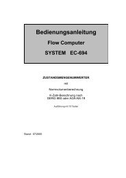
OPERATING INSTRUCTIONS<br />
VOLUME CORRECTOR<br />
with<br />
calculation of the volume at base conditions<br />
and<br />
calculation of the K coefficient in compliance with<br />
GERG 88S or AGA-NX-19<br />
Status: July 2005<br />
Flow Computer<br />
SYSTEM EC 694<br />
10-key design
Contents<br />
Introduction to the EC 694 3<br />
- General information 3<br />
- EC 694 front panel 5<br />
- Description of function keys 6<br />
- Description of special-function keys 7<br />
- Displaying measured values and faults 8<br />
- Special functions to be accessed using the S key 9<br />
- Operating the calibration switch 9<br />
- Inputting the user code 10<br />
- Inputting numeric values 11<br />
- Changing operating modes 12<br />
- Programming the current output 12<br />
- On-the-fly calibration test function 13<br />
- Data-logging memory 14<br />
- Data memory 14<br />
Start Up Instructions 15<br />
- Device variant 15<br />
- Parameterization 16<br />
Coordinate System of the EC 694 18<br />
- Coordinates from A to J 18<br />
- Coordinates from K to O 19<br />
Description of Individual Columns 20<br />
- Column structure 20<br />
- Pressure at measurement conditions 21<br />
- Temperature at measurement conditions (PT 1000) 21<br />
- Analysis 22<br />
- Totalizers 24<br />
- Volume flow rate at measurement conditions 25<br />
- Volume flow rate at base conditions 26<br />
- Flow parameters 27<br />
- Test 29<br />
- Data logger 31<br />
- ID display 34<br />
- Mode 37<br />
- Fault 38<br />
Instructions for Battery Operation 39<br />
- Interrelation between the flow rate and the battery life 39<br />
- Operating modes of the EC 694 43<br />
- Replacement of the supply battery 45<br />
Communication between the EC 694 and the PC 46<br />
Annexes 54<br />
A Equations Used with the EC 694 54<br />
B Block Diagram for the EC 694 56<br />
C Specifications 57<br />
D Fault List 60<br />
E Electrical Connections of the EC 694 62<br />
F Mounting Instructions 73<br />
G Seal Diagrams 85<br />
Index 89<br />
Declaration of Conformity 91<br />
EC Type Approval Certificate 93
Introduction to the EC 694<br />
General information<br />
Introduction to the EC 694<br />
The operating concept<br />
The operating concept has been chosen in such a way that the operator<br />
can easily use the device without wasting too much time reading a<br />
<strong>manual</strong>. If the EC 694 is not yet taken into operation, then read the<br />
chapter "start up instruction" (page 15) in any case.<br />
The function keys<br />
The most important data for the operator can be directly selected via<br />
function keys. The following function keys are available:<br />
– Pressure<br />
– Temperature<br />
– C. Factor<br />
– Totalizer<br />
– ID<br />
The coordinate system<br />
A coordinate system makes it easy for the operator to access all<br />
configuration data as well as measured and calculated values by means of<br />
a table. The coordinate system is based on 15 columns with 31 lines per<br />
column (including header line). The columns are marked A to O. The top<br />
line (header line) is not numbered, whereas the other lines below are<br />
numbered from 1 to 30. The operator can reach every value in this<br />
coordinate system using the cursor keys (arrows � � � �).<br />
The display field<br />
An alphanumeric 2-line display with 16 characters per line enables data<br />
and measured values to be indicated together with their abbreviated<br />
designations and units. The display has been designed as an LCD dot<br />
matrix so that it can be used especially in battery mode. Temperatures<br />
below -20°C or above +60°C may cause a disturbance of the display.<br />
Operating instructions for the EC 694 Volume Corrector 3
Introduction to the EC 694<br />
The system<br />
A complete Flow Computer System has been developed on the surface of<br />
a few square centimeters using the most advanced SMD technology with<br />
large-scale integrated components. Several device functions, such as<br />
pulse counting, frequency measurement, keyboard controller, and<br />
dispatcher output have been incorporated into a controller. Thanks to<br />
large-scale integrated components, fewer chips are required and this also<br />
contributes to making the device reliable. The type of the individual device<br />
essentially depends on the software used.<br />
Program memory<br />
The program memory of the basic unit has been incorporated into a flash<br />
memory located in the vicinity of the controller chip.<br />
Reset<br />
In case of a reset the power supply will be interrupted and the volume<br />
corrector will be switched off for this period of time. Program and operating<br />
parameters are not influenced by this means and also the totalizer<br />
readings are preserved. At the EC 694 a reset is done by disconnecting<br />
the battery as well as a possibly installed external power supply.<br />
4 Operating instructions for the EC 694 Volume Corrector
EC 694 front panel<br />
2-line display with<br />
16 characters per line<br />
Vb 00024765.3 m3<br />
Vm 00003190.2 m3<br />
S C<br />
Keyboard for directly<br />
accessing the various<br />
device functions<br />
Aufkleber<br />
Select<br />
Introduction to the EC 694<br />
Infrared (IR) port<br />
Operating instructions for the EC 694 Volume Corrector 5
Introduction to the EC 694<br />
Description of function keys<br />
Pressure<br />
Temp.<br />
C. Factor<br />
S<br />
Totalizer<br />
>Flow Rate<br />
>Test<br />
C<br />
ID<br />
>Mode<br />
>Fault<br />
Press this function key to display the pressure and use<br />
the � � keys to display all values related to the pressure.<br />
Press the � key to display the fault messages and scroll<br />
up or down using the � � keys.<br />
Press this function key to display the temperature and use<br />
the � � keys to display all temperature-related values.<br />
Press this function key to display the conversion factor<br />
and the K coefficient and use the � � keys to display all<br />
values related to the gas analysis.<br />
• Press this function key to display the totalizer and use<br />
the � � keys to display all values related to the<br />
totalizers.<br />
• Press the � key to display the flow rate and use the �<br />
� keys to display all values related to the flow rate.<br />
• Press the � key to display the test and use the � �<br />
keys to display all values related to the test totalizers.<br />
• Press the � key to display the ID data and scroll up or<br />
down using the � � keys.<br />
• Press the � key to display the operating modes and<br />
scroll up or down using the � � keys.<br />
• Press the � key to display the fault messages and<br />
scroll up or down using the � � keys.<br />
6 Operating instructions for the EC 694 Volume Corrector
Description of special-function keys<br />
� � � � S C<br />
� �<br />
� �<br />
C<br />
↵<br />
Enter<br />
� Coordinate<br />
S<br />
Introduction to the EC 694<br />
Use the � � keys to scroll up or down by lines within a<br />
column. If you press the � key in the first line of a<br />
column, you will jump to the last line of this column. In<br />
input mode, use these keys to increase or decrease<br />
current values or to scroll up or down in texts you are<br />
given for selection.<br />
Use the � � keys to scroll either to the left or right by<br />
columns within a line. Press the � key to jump via the<br />
last column to the first column or press the � key to<br />
jump from the first column to the last column. In input<br />
mode, use these keys to select a digit within a number.<br />
The following applies to cursor keys in general:<br />
Unoccupied columns and lines are automatically<br />
skipped. If the column you jumped to is occupied<br />
but the line field is empty, the first line is selected<br />
automatically.<br />
• Press this key to display ID data directly.<br />
• If the data logger has been activated, press the �<br />
key twice to switch from the volume corrector to the<br />
data logger and vice versa.<br />
• Press the � key once to display operating modes<br />
(Mode).<br />
• Press the � key twice to display faults.<br />
• Press this key to clear any changes entered into a<br />
field in input mode.<br />
• Press this key to initiate a data input but make sure<br />
that the calibration switch is enabled or the user<br />
code was entered previously, depending on the type<br />
of the appropriate field.<br />
• Press this key to complete a data input by<br />
transferring the input value or operating mode to the<br />
computer.<br />
• Press this key to switch over from abbreviated<br />
designations to coordinates, if the computer is not in<br />
input mode.<br />
Press this key to initiate various functions, such as<br />
resetting faults or starting on-the-fly calibration.<br />
Operating instructions for the EC 694 Volume Corrector 7
Introduction to the EC 694<br />
Displaying measured values and faults<br />
Displaying measured values or computational results<br />
• Press either the Pressure or Temperature function key. The measured<br />
value will be displayed in the top line of the display, whereas the<br />
physical value will be displayed in the bottom line.<br />
• Press the C. Factor function key. The conversion factor will appear in<br />
the top line of the display, whereas the K coefficient will be displayed in<br />
the bottom line.<br />
• Press the � key to access subsequent values of the column selected.<br />
Press the � key to access the next column or the � key to access the<br />
previous column.<br />
Displaying faults<br />
The occurrence of a fault is indicated by the special character # in the top<br />
line of the display on the right and by an isolated contact at the terminal<br />
block. This character flashes, if there is a fault. If there are no more faults,<br />
the character turns to steady display.<br />
Use the C key (ID, Mode, Fault) to display fault texts. Press the C key<br />
and then the � key twice or the Pressure key and then the � key once.<br />
Then you will be able to read in the top line of the display how you can<br />
reset the faults displayed. Faults that may have occurred will be displayed<br />
in the bottom line. If more than one fault has occurred, the text displayed<br />
changes approximately every two seconds.<br />
The time and date of the first fault that occurred are displayed in the next<br />
two lines.<br />
Enhanced function: event memory<br />
Moreover, a detailed event memory is available which records not only<br />
fault messages but also other events like parameter changes, interface<br />
operation, resetting of faults, etc. A complete data record including<br />
totalizer readings, pressure, temperature, etc., is stored for each entry into<br />
the data memory.<br />
You can select the event memory <strong>manual</strong>ly in the “Test” column. Press<br />
enter to jump to the last entry.<br />
8 Operating instructions for the EC 694 Volume Corrector
Special functions to be accessed<br />
using the S key<br />
Introduction to the EC 694<br />
The S key comprises several special functions:<br />
– Resetting faults<br />
– In the data-logging memory: Displaying stored values (cf. page 31ff).<br />
– Start, stop and reset in the on-the-fly calibration function (cf. page 13).<br />
Resetting faults<br />
First proceed in the same way as described under displaying faults. Then<br />
you will be given information about resetting fault messages in the top line<br />
of the display. Press the S key to reset the fault messages, provided these<br />
have been released by the computer for acknowledgement. The time and<br />
date of the last fault acknowledgement are displayed in the line O 4.<br />
Operating the calibration switch<br />
cap<br />
interface socket<br />
cover screw for<br />
calibration switch<br />
battery compartment<br />
cable gland<br />
calibration switch<br />
enclosure wall<br />
First remove the cover screw (for fiscal metering, this screw is covered by<br />
a seal) on the right side of the enclosure. Then press a pencil or a screw<br />
driver against the calibration switch until it snaps into place. Now the lock<br />
is removed, and the character I will be displayed in the first position of the<br />
top line. If you press the calibration switch again, the lock will be<br />
reactivated.<br />
Operating instructions for the EC 694 Volume Corrector 9
Introduction to the EC 694<br />
Inputting the user code<br />
First press the C key and then the � key to reach the “Mode” column.<br />
Then press the � key twice. The following lines will be displayed:<br />
MODE<br />
Code * * * *-* * * *<br />
Now press the ↵ key. The bottom line will change as follows:<br />
MODE<br />
Code 0???-????<br />
Now select the first digit of your code number using the � or � key.<br />
Then press the � key. The bottom line will change as follows:<br />
MODE<br />
Code ?0??-????<br />
Now select the second digit and the subsequent ones in the same way as<br />
before. After you have selected the last digit and pressed the � key, the<br />
special character C will be displayed in the first position of the top line of<br />
the display and the initial state will be displayed again in the bottom line of<br />
the display.<br />
You can now change all fields disabled by means of the user-code lock.<br />
This user-code lock is automatically reactivated if you press no key for 30<br />
minutes. You can immediately reactivate the user-code lock <strong>manual</strong>ly if<br />
you press the � key prior to selecting the first digit of the user code as<br />
described above.<br />
If you enable the calibration switch, all fields disabled by means of the<br />
user-code lock are also automatically enabled so that inputs can be made.<br />
It is now even possible to change the user code.<br />
10 Operating instructions for the EC 694 Volume Corrector
Inputting numeric values<br />
Introduction to the EC 694<br />
Since the EC 694 provides no keys for numbers from 0 to 9, the decimal<br />
point or positive or negative signs, you must make your inputs by rolling<br />
the individual digits of a number up or down.<br />
Example:<br />
Changing the pressure default value.<br />
�<br />
• First enable the calibration switch or enter the user code.<br />
• Search the input field for the pressure default value and press the ↵ key<br />
to reach input mode. You can see that you are in input mode if the<br />
special character I (input) or C (code number) is displayed in the first<br />
position of the top line of the display. The input control of the computer<br />
automatically accepts the value of the first digit inputted, which starts to<br />
flash. If the line only switches to displaying coordinates without<br />
displaying I or C, you cannot make any inputs.<br />
p 10.627 bara<br />
pdef 11.250 bara<br />
• You can change the digit using the � � keys.<br />
• Press the � key to reach the next digit and proceed here in the same<br />
way as before. If you press the � key beyond the last possible input<br />
position, the first input digit will be selected again.<br />
• Press the � key to return to one of the previous input positions in order<br />
to correct it and after the first input position to the last position.<br />
• Press the ↵ key again to complete your inputs and store the new value.<br />
• If you enable inputs by pressing the ↵ key and complete them by<br />
pressing this key again without having pressed another key, the<br />
previous value will remain stored. The value stored will not be<br />
overwritten unless it is recognized that the value displayed differs from<br />
the value stored or at least the � key has been pressed.<br />
Operating instructions for the EC 694 Volume Corrector 11
Introduction to the EC 694<br />
�<br />
If you happen to press the C key while making your inputs, the<br />
value inputted will be erased and the original value will be<br />
restored.<br />
You can input a negative sign only with floating-point numbers in<br />
the first input position.<br />
You can input a point only in one position of your input. If the<br />
computer identifies a point, this will be omitted from the selection<br />
of the next digit positions. If a large floating-point number is<br />
changed into a smaller number, it is possible that two points are<br />
visible in the display.<br />
1. If you try to reach the next input position across the second<br />
point by pressing the � key, the latter will be disabled until<br />
you have changed the point.<br />
2. If you try to complete your inputs by pressing the ↵ key, the<br />
input positions after the first point will be set at zero.<br />
After you have completed all your inputs, disable the calibration<br />
switch or disable user access. If user access remains enabled for<br />
more than 30 minutes and no key is pressed during this time, the<br />
computer will automatically disable access to the system.<br />
Changing operating modes<br />
If you want to change an operating mode, first proceed as if you were<br />
changing numeric values. As soon as you reach input mode, select the<br />
desired mode from the menu using the � � keys and press the ↵ key<br />
to accept the mode selected.<br />
Programming the current output<br />
The pressure, temperature, conversion factor or volume flow rate at either<br />
measurement or base conditions can be outputted as a current of 4-20 mA<br />
in the event of external power supply. First select the quantity to be<br />
outputted in coordinate N 12. Then enter the measured values for an<br />
output current of 4 mA into N 14 and for an output current of 20 mA into<br />
N 15. If you have selected “Calibration current” in N 12, a constant current<br />
is outputted which you can set in coordinate O 23.<br />
12 Operating instructions for the EC 694 Volume Corrector
On-the-fly calibration test function<br />
Introduction to the EC 694<br />
Description of the function<br />
The on-the-fly calibration function enables the totalizers for the volume at<br />
measurement conditions and the volume at base conditions to be<br />
operated in parallel with the normal totalizers during a limited period (1<br />
hour). You can start or stop these totalizers through the keyboard. The<br />
running time is shown by a “stop-watch” which runs at the same time. To<br />
enhance resolution, the formats of the totalizers have been expanded to<br />
three decimal places for this operating mode. This function can be used<br />
for an operating point test.<br />
Activating the test<br />
Press the S key and then the � key until the CVb totalizer appears. The<br />
top line will display either<br />
“Start = S Key” (on-the-fly calibration is ready to start and the<br />
totalizers can be started)<br />
or<br />
“Stop = S Key” (on-the-fly calibration is running and the totalizers and<br />
the stop-watch are running)<br />
or<br />
“Reset = S Key” (on-the-fly calibration has been stopped and the<br />
totalizers and the stop-watch can be read and then<br />
reset)<br />
Consequences in the case of battery operation:<br />
During the time on-the-fly calibration is running, the EC 694 will not switch<br />
to energy-saving mode. If the device is operated in the on-the-fly<br />
calibration test function, you must make sure that this function is stopped<br />
automatically after one hour and the device is switched to energy-saving<br />
mode. If this function is performed frequently over the full length of the<br />
running time of one hour, the battery life will be reduced.<br />
Operating instructions for the EC 694 Volume Corrector 13
Introduction to the EC 694<br />
Data-logging memory<br />
The EC 694 has a data-logging memory which can store hourly, daily,<br />
monthly and yearly quantities. For a more detailed description, see the<br />
chapter “Data logger”.<br />
Activating the data-logging memory:<br />
1. Select the “Logger ON” storage mode in coordinate M 25.<br />
2. To set the start date, press the C key twice and then the � key until<br />
“LOG-D” appears. Here enter the start date.<br />
3. To set the start time, press the � key once so that “LOG-T” appears.<br />
Here enter the start time.<br />
As soon as the start time has been reached, a “Logger ON” entry appears<br />
in the event memory. To check this, press the S key and then the � key<br />
until “Start = S key” appears. Now press the � key until you reach “Events”<br />
and then press the S key to display the event memory. Here you can<br />
scroll to check whether “Logger ON” has been entered.<br />
From the time the data-logging memory has been started, a data record is<br />
stored after each complete hour which includes the following values: Vm,<br />
Vb, P, T, VmD, VbD, C and K. These values are entered into several<br />
archives and sorted logically. A maximum of 4,320 entries can be stored<br />
until the circular buffer starts to overwrite the oldest entries. If a To<br />
transducer operating mode has been selected as transducer type mode in<br />
field K 01, the reading of this totalizer is shown additionally.<br />
Data can be read out <strong>manual</strong>ly or using the PVP program via the optical<br />
interface (IR port) on the front panel or the 3-wire interface on the right<br />
side of the device.<br />
Data memory<br />
Activating the data memory<br />
1. Select the “Data M. ON” storage mode in coordinate M 25.<br />
2. Enter the interval into coordinate L 11. Then the data memory will start<br />
immediately with the set interval (no start date).<br />
Each time a time interval has elapsed, a data record is stored with the<br />
values: Vm, Vb, P, T, VmD, VbD, C and K.<br />
A maximum of 720 entries can be stored, until the circular buffer starts to<br />
overwrite the oldest entries.<br />
If data recording is made on a minute basis, the battery life will be reduced<br />
to a maximum of two years.<br />
Data can be read out <strong>manual</strong>ly through the keyboard associated with the<br />
device or using the PVP program via the 3-wire interface or the optical<br />
interface (IR port).<br />
14 Operating instructions for the EC 694 Volume Corrector
Start-Up Instructions<br />
Device variants<br />
Coordinate System Overview<br />
The following table shows the possible device variants which differ in<br />
power supply and pulse input. See the supplied documents to determine<br />
which device variant is concerned.<br />
Pulse input Pulse output Current output<br />
Battery-powered<br />
device (Ex)<br />
- Reed Switch it on in K 25 Not possible!<br />
9.2 V supply (Ex) - Reed<br />
Switched on Only passive<br />
- Reed / Namur on delivery operation<br />
- Namur<br />
permissible<br />
- Wiegand<br />
(explosion<br />
protection)<br />
24 V supply (non - Reed<br />
Switched on Operation<br />
Ex)<br />
- Reed / Namur on delivery - active or<br />
- Namur<br />
- Wiegand<br />
- passive<br />
Instructions for connection<br />
1. If the EC 694 is operated with only one pulse input, the pulse<br />
transmitter is to be connected to terminals 21 and 22.<br />
2. In the case of combined Reed / Namur operation, pulse counting (Vm)<br />
is performed via the Reed input (terminals 21 and 22). Namur pulses<br />
are used for the flow display and the current output; the Namur<br />
transmitter is to be connected via terminals 4 (+) and 5 (-).<br />
3. Note the polarity of the output pulses. If necessary, use a polarity<br />
converter (available as accessory under the order number<br />
50.36.763.00).<br />
4. In the case of devices with battery backup, you must check after startup<br />
whether the battery is connected and enabled.<br />
5. The current output (4-20 mA) is to be connected differently for active<br />
and passive operation:<br />
- active: Connection to terminals 13 (-) and 14 (+).<br />
An external power supply must not be used in no event.<br />
If you connect an external voltage, this will result in the<br />
destruction of the current output!<br />
There is no electrical isolation towards the 24 V supply of<br />
the EC 694.<br />
- passive: Power is supplied by an external supply unit, connection to<br />
terminals 13 (+) and 14 (-).<br />
6. To output a current (qVm or qVb), the input frequency must exceed<br />
2 Hz!<br />
7. The cable towards the temperature pick-up can be up to 25 m in<br />
length. It can be up to 3 m in length towards an external pressure<br />
transmitter!<br />
Operating instructions for the EC 694 Volume Corrector 15
Coordinate System Overview<br />
Parameterization<br />
During start-up, it is necessary to set or change several parameters.<br />
The most important ones are listed below. Please proceed in the same<br />
order, since some parameters are displayed or can be changed only<br />
after other parameters have been programmed. The coordinate of the<br />
parameter and the default value (DV) of common values are shown in<br />
parentheses.<br />
Parameters which must always be programmed:<br />
1. Define whether the EC 694 is to be operated by battery or an external<br />
power supply unit and whether the flow rate (O 22) is to be shown (for<br />
operation with HF pulses). If the mode is changed, you must disconnect<br />
the EC 694 from its power supply or battery for a short time.<br />
2. Select the procedure for calculating the K coefficient (G 12, DV: GERG-<br />
88-S).<br />
3. Select the physical unit for pressure (A 13, DV: bar a).<br />
4. Replacement value for pressure which is used when a fault occurs in<br />
pressure measurement (A 6).<br />
5. Standard pressure (A 8, DV: 1.01325 bar*)<br />
6. Replacement value for temperature which is used when a fault occurs<br />
in temperature measurement (F 6).<br />
7. Standard temperature (F7 with AGA-NX-19 and K=const, F 8 with<br />
GERG-88-S and AGA-8; DV: 0°C*).<br />
8. Select the physical unit for the superior calorific value (G 21, DV:<br />
kWh/m 3 ).<br />
9. Analytical values for calculating the K coefficient in accordance with<br />
GERG-88-S: superior calorific value (G 20), standard density (G 19)<br />
and CO2 content (G 17). For calculations in accordance with AGA-NX-<br />
19: superior calorific value (G 20), relative density (G 19) and N2<br />
content (G 18).<br />
10. Select the reference temperature for the superior calorific value<br />
(G 22, DV: 25°C*)<br />
11. Pulse value of the meter for volume measurement (K 2) and flow<br />
calculation (K 13, only with Reed / Namur version). The preset value is<br />
normally only a value for testing!<br />
12. Set whether and how switching over to summer/winter time is to be<br />
made (N 28).<br />
* This value is mandatory in Germany.<br />
16 Operating instructions for the EC 694 Volume Corrector
Coordinate System Overview<br />
Parameters which have to be programmed depending on the<br />
operating mode:<br />
1. In the case that flow display is enabled: Measuring range of the gas<br />
meter with qmmin (I 4) and qmmax (I 5). In the case of ¼ qmmin, the<br />
input frequency should exceed 2 Hz.<br />
2. Program the pulse outputs with select mode (K 25), mode for<br />
assignment to Vm or Vb (K 26), scaling factors (H 10 and H 12) and<br />
pulse period and interpulse period (K 27 to K 30).<br />
3. Program the current output by selecting the quantity to be outputted (N<br />
12) and the output limits I< (N 14, for 4 mA) and I><br />
(N 15, for 20 mA).<br />
Operating instructions for the EC 694 Volume Corrector 17
Coordinate System Overview<br />
Coordinate System of the EC 694<br />
Coordinates from A to J<br />
Pressure Temperature Analysis Totalizers Flow rate 1 Flow rate 2<br />
A / 01 F / 06 G / 07 H / 08 I / 09 J / 10<br />
0 Meas. val. 1 bara °C C Vb qm qb<br />
1 Meas. val. 2 K To<br />
2 Input / Tot Up ohm Zb Vm fqm<br />
3 Input / Tot Z<br />
4 Min. range p min. t min. qm min.<br />
5 Max. range p max. t max. VbD qm max.<br />
6 Default p default t default K fixed val.<br />
7 Spare tb AGA VmD<br />
8 Reference pb tb GERG<br />
9 Correction factor CA qmA qbA<br />
10 Min. contact O1 scaling factor<br />
11 Max. contact<br />
12 Mode 1 ON / Def ON / Def K calc.mode O2 scaling factor<br />
13 Mode 2 p unit t unit<br />
14 Mode 3 Totalizer mode<br />
15 Mode 4<br />
16 Calc. val. rho calc.<br />
17 Calc. val. CO2<br />
18 Calc. val. Umin H2 / N2<br />
19 Calc. val. pumin sd / rd<br />
20 Constant pc t corr. Hs<br />
21 Constant pA0 Hs unit fqb<br />
26 Special VmP t>qm t>qb<br />
27 Spare<br />
28 Spare<br />
29 Spare<br />
30 Spare<br />
Display field<br />
Input field locked via code number<br />
Input field locked via calibration switch<br />
18 Operating instructions for the EC 694 Volume Corrector
Coordinates from K to O<br />
Coordinate System Overview<br />
Flow parameters Test ID Mode Fault<br />
K / 11 L / 12 M / 13 N / 14 O / 15<br />
0 Special Heading Heading ID MODE FAULT<br />
1 Special Operating mode CVb p type Time Fault text<br />
2 Special Kv p No. Date Fault time<br />
3 Special Unit CVm p min. Code No. Fault date<br />
4 Special p max. Prog. date Last reset<br />
5 Special t type Operating hours<br />
6 Special Set-Vb C duration t No. RS-IR mode<br />
7 Special Set-Vm LOG-D t min. RS-IR baud rate<br />
8 Special Pulse scal. factor LOG-T t max. RS-4-wire mode<br />
9 Special Set-To LOG-I M type RS-4-wire bd rate<br />
10 Special M No. RS-service mode<br />
11 Special DAT-I M size RS-service bd rate<br />
12 Special Mant. Data memory M min Imod<br />
13 Special KTo Cur. hourly qty M max Output current Supply voltage<br />
14 Special Last hourly qty Kv I< clk<br />
15 Special Max. hourly qty Gas type I><br />
16 Special To mode IA<br />
17 Special q mode Bat. change Emer. power<br />
18 Special<br />
19 Special Pulse input<br />
20 Special Test<br />
21 Special<br />
22 Special Lamp test Hardw. type<br />
23 Special L-Source Quartz frequency Ical<br />
24 Special L-Pulses Bit3D Iout corr.<br />
25 Special Output pulse select TD gas day D.log./D.mem. Iout corr.<br />
26 Special Output pulse assign TM gas month L-Test<br />
27 Special Output1 pulse width TAH hourly rec. Computer No.<br />
28 Special Output1 pause width TAD daily rec. Time zone<br />
29 Special Output2 pulse width TAM monthly rec. Computer type Summer time<br />
30 Special Output2 pause width E events Software vers. Winter time<br />
Display field<br />
Input field locked via code number<br />
Input field locked via calibration switch<br />
Operating instructions for the EC 694 Volume Corrector 19
Description of Individual Columns<br />
Description of Individual Columns<br />
Column structure<br />
�<br />
EC 694<br />
function key<br />
Sequence of key operations<br />
required to reach the<br />
desired column<br />
Press the above function key and then the � key once.<br />
A Description of coordinates Unit<br />
H D p Measured value for pressure (absolute pressure) bara<br />
2 D Up Measured value for input voltage V<br />
4 S pmin Lower adjusting value and fault limiting value bara 2)<br />
8 S pb Pressure at base conditions (reference quantity) bara<br />
Brief description of<br />
the matrix field<br />
Abbreviated field designation<br />
in the display of the EC-694<br />
Coding of matrix fields:<br />
H = Header line<br />
D = Display value<br />
C = Access to a data field protected<br />
by the user code<br />
S = Access to a data field protected<br />
by the calibration switch<br />
Designation of a<br />
column line.<br />
The header line (H) is<br />
not outputted in the<br />
coordinate display<br />
mode.<br />
Designation of columns A...O<br />
Unit of the value<br />
displayed or<br />
programmed<br />
Explanatory notes on a<br />
coordinate field<br />
20 Operating instructions for the EC 694 Volume Corrector
Pressure at measurement conditions<br />
�<br />
Pressure<br />
Description of Individual Columns<br />
A Description of coordinates Unit 2)<br />
H D p Measured value for pressure (absolute pressure) bara<br />
2 D Up Measured value for input voltage V<br />
4 S pmin Lower adjusting value and fault limiting value bara<br />
5 S pmax Upper adjusting value and fault limiting value bara<br />
6 C pdef Default value (replacement value if a fault occurs) bara<br />
8 S pb Pressure at base conditions (reference quantity) bara<br />
12 S pmod1 Current input mode p = ON / Default 1)<br />
13 S pmod2 Unit mode: switching units for display 1) 3)<br />
18 S Umin Constant from basic calibration of the pressure transducer V 4)<br />
19 S pumin Constant from basic calibration of the pressure transducer bara 4)<br />
20 S pc Constant from basic calibration of the pressure transducer 4)<br />
21 S pA0 Correction value for pressure transducer 4)<br />
22 S pA1 Correction value for pressure transducer 4)<br />
1) Rolling texts! Use the � � keys to make your changes.<br />
2) The units displayed in the appropriate fields vary depending on the<br />
operating mode selected in field A 13 (option).<br />
3) Options: bara kg/cm 2 a<br />
4) The values of A 18 through A 20 are determined during the initial<br />
pressure transducer test. Umin is the voltage supplied by the<br />
pressure transducer at the lowest test pressure pumin, whereas pc is<br />
the calibration factor. With the voltage U at the pressure transducer,<br />
the pressure can be calculated as follows:<br />
p uncorr . = pu min + pc ⋅ ( U − U min).<br />
Using the values pA0 and pA1, it is possible to make a fine<br />
adjustment (during the volume corrector test), so that the pressure at<br />
measurement conditions p can be calculated as follows:<br />
= p ⋅ pA0<br />
+ pA1<br />
p uncorr .<br />
The two correction values can be calculated as follows:<br />
0 = ( p − p ) / ( p − p<br />
pA specified(max)<br />
specified(min)<br />
actual(max)<br />
actual(min)<br />
pA1 =<br />
p − pA0<br />
⋅ p<br />
specified(max)<br />
actual(max)<br />
Operating instructions for the EC 694 Volume Corrector 21<br />
)
Description of Individual Columns<br />
Temperature at measurement conditions (PT 1000)<br />
�<br />
Temp.<br />
F Description of coordinates Unit 2)<br />
H D t Measured value for gas temperature °C<br />
2 D Rt Input resistance ohm<br />
4 S tmin Lower fault limiting value °C<br />
5 S tmax Upper fault limiting value °C<br />
6 C tdef Default value (replacement value if a fault occurs) °C<br />
7 S tb Temperature at base conditions (AGA-NX-19, Beattie, K=const.) °C 4)<br />
8 S tb Temperature at base conditions (GERG, NX-19-corr, AGA-8) °C 1) 4)<br />
12 S tmod1 Temperature input mode t = ON / Default 1)<br />
13 S tmod2 Unit mode: switching units for display 3)<br />
20 S tc Correction factor: balancing A/D converter offset<br />
1) Rolling texts! Use the � � keys to make your changes.<br />
2) The units displayed in the appropriate fields vary depending on the<br />
operating mode selected in field F 13.<br />
3) Options: °C / K / °F<br />
4) If the AGA-NX-19, Beattie-Bridgeman or K=const. operating modes<br />
is selected in field G 12, use field G 7 to freely enter the temperature<br />
at base conditions. In GERG-88-S, AGA-8 or AGA-NX-19-corr<br />
operating modes, the temperature at base conditions can only be<br />
selected from among the options of field F 8 (0 / 15 / 15.56 / 20 and<br />
25°C).<br />
22 Operating instructions for the EC 694 Volume Corrector
Analysis<br />
�<br />
C. Factor<br />
Description of Individual Columns<br />
G Description of coordinates Unit<br />
H D C Conversion factor<br />
1 D K Gas law deviation coefficient<br />
2 D Zb Compressibility factor at base conditions<br />
3 D Z Compressibility factor at measurement conditions<br />
6 C Kdef Fixed value for K coeffient<br />
9 C CA Conversion factor damping<br />
12 S Kmod1 K coefficient calculation mode = K const / Beattie / GERG-88-S /<br />
AGA-NX-19 / NX-19-corr / AGA-8<br />
16 D ra Calculated density kg/m3<br />
17 C CO2 Carbon dioxide content % 5)<br />
18 C H2 or N2 Hydrogen content (GERG-88-S) or nitrogen content (AGA-NX-19) % 5)<br />
19 C sd or rd Standard density (GERG-88-S) or relative density (AGA-NX-19) kg/m3 5)<br />
20 C Hs Superior calorific value kWh/m3 2) 5)<br />
21 C Kmod5 Unit mode: switching units for display 3)<br />
22 S Kmod6 Reference temperature mode: 25 / 20 / 15 / 0 °C 1) 4)<br />
1) Rolling texts! Use the � � keys to make your changes.<br />
2) The unit displayed in field G 20 varies depending on the operating<br />
mode selected in field G 21.<br />
3) Options: kWh/m 3<br />
MJ/m 3<br />
kcal/m 3<br />
Mcal/m 3<br />
BTU/ft 3<br />
4) Combustion temperature to which the superior calorific value is<br />
related.<br />
5) Not displayed with Beattie.<br />
6) AGA-NX-19: without H-group gas correction<br />
NX-19-corr: with H-group gas correction<br />
Operating instructions for the EC 694 Volume Corrector 23<br />
1) 6)
Description of Individual Columns<br />
Totalizers<br />
� S<br />
Totalizer<br />
> Flow Rate<br />
> Test<br />
H Description of coordinates Unit<br />
H D Vb Main totalizer for volume at base conditions m3 3)<br />
1 D To Reference totalizer for volume at measurement conditions m3 3) 5)<br />
2 D Vm Main totalizer for volume at measurement conditions m3 3)<br />
5 D VbD Disturbing quantity totalizer for volume at base conditions m3<br />
7 D VmD Disturbing quantity totalizer for volume at measurement conditions m3<br />
10 S O1sf Scaling factor for output contact 1 (0.1 – 100,000) m3/I 4)<br />
12 C O2sf Scaling factor for output contact 2 (0.1 – 100,000) m3/I 4)<br />
14 S Tmod1 Totalizer mode = Fault stop / Fault cont 1) 2)<br />
26 C VmP Settable totalizer for volume at measurement conditions (no fiscal metering) m3 6)<br />
1) Rolling texts! Use the � � keys to make your changes.<br />
2) Tmod1 = Fault stop: In the event of an alarm, the main totalizers stop<br />
and the disturbing quantity totalizers start to run.<br />
Tmod1 = Fault cont: In the event of an alarm, the main totalizers<br />
continue to run, and in addition to this, the<br />
disturbing quantity totalizers start to run.<br />
3) The totalizers can be set in column K (flow parameters).<br />
4) The scaling factors can be selected freely, but you must note that the<br />
maximum pulse rate is 3 pulses per second. If the output is assigned<br />
to a totalizer for fiscal metering (see coordinate K 25), programming is<br />
only possible if the calibration switch was enabled previously. If the<br />
output is assigned as a dispatcher output, the user code is sufficient.<br />
5) The To totalizer is used as a check totalizer in conjunction with a<br />
mechanical totalizer. It even continues to count if there is a fault. It has<br />
its own pulse values for both LF and HF transducers and can be<br />
adjusted to comply with the representation of the mechanical totalizer.<br />
It is settable and also available in emergency power supply mode and,<br />
if the data logger has been activated, its readings are stored in the<br />
hourly and daily data archives.<br />
6) This additional totalizer is independent of Vm, Vb and To and is set<br />
directly, not in column K.<br />
24 Operating instructions for the EC 694 Volume Corrector
Volume flow rate at measurement conditions<br />
Description of Individual Columns<br />
This column is not available for battery/mains-powered devices without an<br />
activated display of the flow rate.<br />
� S<br />
Totalizer<br />
> Flow Rate<br />
> Test<br />
Press the above function key and the � key once.<br />
I Description of coordinates Unit<br />
H D qm Calculated volume flow rate at measurement conditions m3/h<br />
2 D fqm Input frequency Hz 1)<br />
4 S qmmin Lower fault limiting value of the volumetric meter m3/h<br />
5 S qmmax Upper fault limiting value of the volumetric meter m3/h<br />
9 C qmA Damping of the volume flow rate at measurement conditions<br />
21 S f
Description of Individual Columns<br />
Volume flow rate at base conditions<br />
This column is not available for battery/mains-powered devices without an<br />
activated display of the flow rate.<br />
� S<br />
Totalizer<br />
> Flow Rate<br />
> Test<br />
Press the above function key and the � key twice.<br />
J Description of coordinates Unit<br />
H D qb Volume flow rate at base conditions m3/h<br />
9 C qbA Damping of the volume flow rate at base conditions<br />
25 D >qb Maximum value of the volume flow rate at base conditions m3/h 1)<br />
26 D t>qb Time of maximum value (date / time)<br />
1) Resetting the maximum value: – Unlock the user-code lock.<br />
– Select the maximum value.<br />
– Press enter.<br />
26 Operating instructions for the EC 694 Volume Corrector
Flow parameters<br />
� S<br />
Totalizer<br />
> Flow Rate<br />
> Test<br />
Description of Individual Columns<br />
Press the above function key and then the � key once (batterypowered<br />
device).<br />
Press the above function key and then the � key three times (in the<br />
event of external power supply).<br />
K Description of coordinates Unit<br />
H D Header text Flow parameters<br />
1 S qmod1 Transducer type mode: 1*Reed-/Nam 1)<br />
2 S Kv Volumetric meter pulse value P/m3<br />
3 S Emod1 Unit of flow rate 1)<br />
6 S Set-Vb Setting the main totalizer for volume at base conditions<br />
7 S Set-Vm Setting the main totalizer for volume at measurement conditions<br />
8 S Puls Pulse scaling factor 1 / 2 / 5 / 10 / 20 / 50 / 100 / 300 / 600 P 1)<br />
9 S Set-To Setting the To totalizer<br />
12 S Mant. Adjusting the representation of the check totalizer to comply with the<br />
mechanical totalizer: 6 Digits / 7 Digits / 8 Digits / 9 Digits<br />
13 S KTo Pulse value of the volume transducer’s HF pick-off P/m 3<br />
16 S Tomod Mode To totalizer: TO OFF / TO Softw. / TO Hardw.<br />
17 S qmod Mode flow rate display: qm ON / qm OFF<br />
19 S PInp Selection of input pulses: Tot.-Reed / Tot.-Nam<br />
25 C Dmod2 Pulse output mode : selection 1) 2)<br />
26 C Dmod3 Pulse output mode: assigning pulse outputs to the totalizers 1) 3)<br />
27 C Pwdth1 Pulse width of totalizer outputs 10 / 20 / 30 / 40 / 50 / 75 / 100 / 125 / 150 /<br />
175 / 200<br />
ms 1) 4)<br />
28 C Pper1 Pulse pause width of totalizer outputs 10 / 20 / 30 / 40 / 50 / 75 / 100 / 125 /<br />
150 / 175 / 200<br />
ms 1) 4)<br />
29 C Pwdth2 Pulse width of totalizer outputs 10 / 20 / 30 / 40 / 50 / 75 / 100 / 125 / 150 / ms 1) 4)<br />
175 / 200<br />
30 C Pper2 Pulse pause width of totalizer outputs 10 / 20 / 30 / 40 / 50 / 75 / 100 / 125 /<br />
150 / 175 / 200<br />
ms 1) 4)<br />
1) Rolling texts! Use the � � keys to make your changes.<br />
2) The device has two volume pulse outputs (indicated in the display as<br />
OUT1 and OUT2) which can be selected as totalizer outputs for fiscal<br />
metering or as dispatcher outputs.<br />
Battery-powered devices: If the pulse outputs are not needed, they<br />
should be deactivated to save battery power.<br />
Options: TON: totalizer output ON (fiscal metering)<br />
DON: dispatcher output ON (no fiscal metering)<br />
OFF: pulse output deactivated<br />
In the mode "TON" no pulses are outputted if the volume corrector is<br />
disturbed. In the mode "DON" the summed pulses are outputted both<br />
in the disturbed and in the undisturbed state.<br />
Operating instructions for the EC 694 Volume Corrector 27
Description of Individual Columns<br />
3) Assigning the pulse outputs to Vm or Vb<br />
Options: OUT1 OUT2<br />
Vb Vb<br />
Vm Vm<br />
Vb Vm<br />
Vm Vb<br />
(See coordinates H 10 and H 12 for scaling factors)<br />
4) For battery-powered devices, we would recommend you to select the<br />
pulse width as small as possible, since higher values will reduce the<br />
service life of the battery.<br />
5) The possible settings in field K-1 depend on the type of hardware.<br />
There are the following 3 variants:<br />
a) in the case of devices with the standard card (Reed/Namur)<br />
"1*Reed/Nam." is displayed. In field K-19 you can select whether<br />
the Reed pulses (always via the terminals 21/22) or the Namur<br />
pulses (terminals 4/5) are used for Vm counting. If both inputs are<br />
used, then the Reed pulses are counted into the totalizers Vb and<br />
To (Tomod in K-16 set to "TO Softw.") and the Namur pulses are<br />
used for the flow rate calculation (qMod in K-17 set to "qm ON")<br />
and for the current output.<br />
b) in the case of devices with Namur card "1*Nam" or "2*Nam" can<br />
be selected. The selection of "Tot.-Reed" in field K-19 is not<br />
possible.<br />
c) in the case of devices with Reed card "1*Reed" or "2*Reed" can<br />
be selected. The selection of "Tot.-Namur" in field K-19 is not<br />
possible, the field K-17 is not visible.<br />
6) This field is displayed only if the mode in field K-17 is set to "qm ON".<br />
Here the meter pulse value of the Namur volume pulse transmitter<br />
must be entered.<br />
7) This field is displayed only if the totalizer To is activated (settable in<br />
K-16).<br />
28 Operating instructions for the EC 694 Volume Corrector
Test<br />
� S<br />
Totalizer<br />
> Flow Rate<br />
> Test<br />
Description of Individual Columns<br />
Press the above function key and then the � twice (battery-powered<br />
device).<br />
Press the above function key and then the � key four times (in the<br />
event of external power supply).<br />
L Description of coordinates Unit<br />
H D Header text (Text varies depending on the on-the-fly calibration status)<br />
1 D CVb On-the-fly calibration: totalizer for volume at base conditions<br />
3 D CVm On-the-fly calibration: totalizer for uncorrected volume at meas. conditions<br />
6 D C-durat Duration of the on-the-fly calibration s<br />
30 D E EVENTS Event archive 1)<br />
1) Event memory<br />
If the heading “E EVENTS” appears in the display, press the S key to<br />
display the contents of the event memory. The time and date (time<br />
stamp) associated with the events will appear in the top line of the<br />
display. Press the S key again to return to the “Test” column.<br />
Press enter to jump to the last (current) entry. If you press the<br />
C. Factor key, you can switch between the time stamp and the index<br />
(internal numbering) in the top line of the display.<br />
Storage depth: 400 entries<br />
Events stored: All operations carried out on the EC 694, such as<br />
changing values, fault messages, enabling or disabling the calibration<br />
switch, etc.<br />
Structure of an entry in the event memory:<br />
• Event in plain text (if there is a "+" before, then this means the<br />
occurrence of the event or the beginning of an action or a<br />
disturbance. In combination with a "-" the end of a disturbance or an<br />
action is marked.)<br />
• Time of the entry<br />
• The current values of: Vm, Vb, VmD, VbD, p, T, Zu, K<br />
• With the mode "qm ON" (field K-17): Qm, Qb<br />
Operating instructions for the EC 694 Volume Corrector 29
Description of Individual Columns<br />
List of the events recorded additionally to the fault and warning messages:<br />
Message text Description<br />
Hour change Entry into hourly archives (only in test operation)<br />
Day change Entry into daily archives (only in test operation)<br />
Month change Entry into monthly archives (only in test operation)<br />
Field input x-xx Change of a computer parameter with indication of column and line<br />
+Input switch Calibration switch has been opened<br />
-Input switch Calibration switch has been closed<br />
+User code Password has been entered<br />
-User code Locked again by password<br />
Fault reset Manual acknowledgement of the entries in the error display<br />
(field O-1)<br />
+RS inquiry Waking up the computer in battery operation via receipt of a<br />
character on one of the serial interfaces with the PVP protocol<br />
-RS inquiry Falling asleep of the computer after the transmission of the last<br />
character on one of the serial interfaces, if no new character has<br />
been received via one of the interfaces within 20 seconds<br />
test mode on Test mode has been switched on<br />
test mode off Test mode has been switched off. (this takes place automatically<br />
60 minutes after last pressing a key)<br />
Data memory on Switching on the data logger<br />
Data memory off Switching off the data logger<br />
Data log mem.on Switching on the tariff memory<br />
Data log mem.off Switching off the tariff memory<br />
Totalizer reset Resetting of all totalizers and pulse outputs<br />
TD-memory reset maximum hourly quantity memory (hourly maximum of the last tariff<br />
day) reset * )<br />
TM-memory reset maximum daily quantity memory (daily maximum of the last tariff<br />
month) reset * )<br />
TAH-memory reset Hourly archives reset * )<br />
TAD-memory reset Daily archives reset * )<br />
TAM-memory reset Monthly archives reset * )<br />
ET-memory reset Event memory reset<br />
Time = MEST Change-over from winter to summer time<br />
Time = MET Change-over from summer to winter time<br />
+backup battery Switching to backup battery supply<br />
-backup battery Switching back to mains supply<br />
store operation Store operation switched on<br />
battery oper. Battery supply switched on<br />
extern -Fl Mains supply without flow rate calculation switched on<br />
extern +Fl Mains supply with flow rate calculation switched on<br />
*) The events "TD -, TM -, TAH -, TAD and TAM-memory reset" are<br />
initiated together by only one command. Separate resetting of the<br />
individual memories is not possible.<br />
30 Operating instructions for the EC 694 Volume Corrector
Data logger<br />
� C (twice)<br />
ID<br />
> Mode<br />
> Fault<br />
Description of Individual Columns<br />
L Description of coordinates Unit<br />
7 S LOG-D Start date of data logging<br />
8 S LOG-T Start time of data logging<br />
9 D LOG-I Recording interval of the data-logging memory h 1)<br />
11 C DAT-I Recording interval of the data memory 2)<br />
12 D DATA MEMORY Heading 2)<br />
13 D CUR. HOURLY QUAN Current hourly value 1)<br />
14 D LAST HOURLY QUAN Last hourly data 1)<br />
15 D MAX. HOURLY QUAN Maximum hourly data 1)<br />
25 D TD GAS DAY Maximum hourly data of a gas day 1)<br />
26 D TM GAS MONTH Maximum daily data of a calendar month 1)<br />
27 D TAH HOURLY REC. Hourly data 1)<br />
28 D TAD DAILY REC. Daily data (accumulated hourly quantities of a gas day) 1)<br />
29 D TAM MONTHLY REC. Monthly data (accumulated hourly quantities of a calendar month) 1)<br />
In field M 25, you can activate either the data memory or the data-logging<br />
memory. If the data-logging memory has been selected, only the fields<br />
identified by 1) are visible, whereas the fields identified by 2) are only<br />
visible if the data memory has been activated.<br />
1) Data-logging memory<br />
If the data-logging memory has been activated (field M 25), you can<br />
switch between the volume corrector and the data logger by pressing<br />
the C key twice. Use the arrow keys � � to select the desired datalogging<br />
memory from the menu and press the S key to display it. The<br />
time stamp of the measured values will appear in the top line of the<br />
display. Press the S key again to return to the selection menu.<br />
Operating instructions for the EC 694 Volume Corrector 31
Description of Individual Columns<br />
To operate the data logger, use the following keys:<br />
• Pressure, Temp. and C. Factor keys<br />
Without any function<br />
• C key<br />
Press this key twice to return to the volume corrector.<br />
• S key<br />
Switching between the selection menu and displaying memory<br />
contents (display mode) of the preselected menu item.<br />
• � key<br />
Within the selection menu: Displaying the previous menu item.<br />
Within the memory: Scrolling forwards by hours and jumping from<br />
the last to the first entry if the end of the memory has been reached.<br />
• � key<br />
Within the selection menu: Displaying the next menu item.<br />
Within the memory: Scrolling backwards by hours and jumping to<br />
the last entry if the beginning of the memory has been reached.<br />
• � or � key<br />
Displaying individual measured values (e.g. Vm, Vb, etc.) in display<br />
mode.<br />
• ↵ key<br />
Jumping to the current entry.<br />
Retrievable memories<br />
The following menu items can be retrieved within the data logger:<br />
TD GAS DAY<br />
Maximum hourly quantity of a gas day.<br />
Storage depth: 370 days<br />
Data stored: Vm and Vb.<br />
TM GAS MONTH<br />
Maximum daily quantity of a calendar month.<br />
Storage depth: 14 months<br />
Data stored: Vm and Vb.<br />
32 Operating instructions for the EC 694 Volume Corrector
TAH HOURLY REC.<br />
Hourly data archive.<br />
Storage depth: 4,320 hours (= 180 days)<br />
Data stored: Vm, Vb, VmD, VbD, To, p and t.<br />
TAD DAILY REC.<br />
Accumulated hourly data of a gas day.<br />
Storage depth: 370 days<br />
Data stored: Vm, Vb, VmD, VbD, To, p and t.<br />
TAM MONTHLY REC.<br />
Accumulated hourly data of a calendar month.<br />
Storage depth: 14 months<br />
Data stored: Vm, Vb, VmD, VbD, To, p and t.<br />
Description of Individual Columns<br />
The To entries show the totalizer readings and not the quantities for<br />
the logging intervals.<br />
The To totalizer in the TAH, TAD and TAM archives is only displayed if<br />
the appropriate mode has been selected in field K 1.<br />
The hourly data for pressure, temperature, conversion factor and<br />
K coefficient are averaged!<br />
2) Data memory<br />
If the data memory has been activated, the heading “DATA<br />
MEMORY” will appear. Now you have the following options:<br />
�: Press this key to switch to the time interval (selectable,<br />
field L 11).<br />
C: Press this key twice to return to the volume corrector.<br />
S: Press this key to display the memory contents.<br />
The time stamp of the measured values will be displayed in the<br />
top line of the display. Now you can press the � and � keys to<br />
scroll in the entries, and if you press � or � you can display the<br />
individual measured values. Press enter to jump to the last<br />
(current) entry or press the C key twice to return to the volume<br />
corrector.<br />
Storage depth: 720 entries<br />
Data stored: Vm, Vb, VmD, VbD, p, t, C and K.<br />
Operating instructions for the EC 694 Volume Corrector 33
Description of Individual Columns<br />
ID display<br />
� C<br />
ID<br />
> Mode<br />
> Fault<br />
M Description of coordinates Unit 2)<br />
H D Header text ID<br />
1 S ptype Pressure transducer select mode 1) 6)<br />
2 S pNo Pressure transducer number<br />
3 S pmin Minimum range of the pressure transducer bara<br />
4 S pmax Maximum range of the pressure transducer bara<br />
5 S ttype Resistance thermometer select mode: PT 1000 1)<br />
6 S tNo Number of the resistance thermometer<br />
7 S tmin Minimum range of the resistance thermometer °C 2)<br />
8 S tmax Maximum range of the resistance thermometer °C 2)<br />
9 S Mtype Gas meter type select mode: G4–G16000 / TM / Terz / RDM / VM / DGM 1)<br />
10 S MNo Gas meter number 4)<br />
11 S Msize Gas meter size 4)<br />
12 S Mmin Minimum range of the gas meter m3/h 4)<br />
13 S Mmax Maximum range of the gas meter m3/h 4)<br />
14 S Kv Gas meter pulse value P/m3 4)<br />
15 S Gas: Gas type, e.g. natural gas 1) 5)<br />
17 C BC-in Time until the next battery replacement months<br />
23 S LSour. Origin of the test pulses for the data logging memory: Intern / Extern<br />
24 S LPuls Presetting of the number of pulses for the test of the data logging memory<br />
25 S Lmod Selection of data-logging memory / data memory 1) 3)<br />
26 S LTest Start of the test programm for the data logging memory 1)<br />
27 S C-No Serial number of the computer<br />
29 S Cmod Operating mode of the computer: pt-stand. 1)<br />
30 D Ver. pt Version of the software installed<br />
1) Rolling texts! Use the � � keys to make your changes.<br />
2) The units displayed in the appropriate fields vary depending on the<br />
operating mode selected in columns A and F.<br />
3) Options: OFF / Logger ON / Data M. ON<br />
4) These fields are only displayed by mains-powered devices.<br />
5) Natural gas, hydrogen, nitrogen, oxygen, air, ammonia, carbon<br />
dioxide, helium, neon, argon, methane, ethane, ethylene, propane, nbutane,<br />
krypton, xenon.<br />
6) DA09/2, DA09/5, DA09/10, DA09/20, DA09/40, DA09/70<br />
7) See the description of this test function on the next pages.<br />
8) Only visible if LTest (M26) is set to “Log. test”.<br />
34 Operating instructions for the EC 694 Volume Corrector
Test of the data logging memory<br />
Description of Individual Columns<br />
Function:<br />
By means of the tariff test the user is enabled to test the temporal,<br />
quantitative and contentwise sequence of the memory entries into the<br />
hourly, daily and monthly archives as well as the resulting entries in the<br />
maximum quantity memory, also during operation. The setting is possible<br />
only via opening the calibration switch. Maximally 20 tariff entries are<br />
possible, whereby a change of hour represents one entry. A change of day<br />
means two entries (1x change of hour plus 1x change of day) and the end<br />
of a month therefore causes three entries.<br />
The tariff entries are caused by external or internally generated pulses<br />
(selection in field M-23).<br />
NOTE:<br />
The test uses the Unix time format for the temporal calculations. Here the<br />
seconds are counted by means of 1-second intervals since 1.1.1970.<br />
During normal operation "Unix time" and standard time are identical. If the<br />
time is changed, the Unix time is adapted automatically. This applies also<br />
to the change-over between summer and winter time.<br />
During the tariff test the time read out from a clock chip is stopped, and<br />
only the "Unix time", fed from 1-second pulses is used. However if a<br />
change-over between summer and winter time should take place during<br />
the tariff test, this is not possible.<br />
In addition the device, if it is battery-powered, does not go to sleep, so that<br />
in this time a permanent power consumption from the battery takes place.<br />
Furthermore the current output is switched off and the interfaces are<br />
blocked.<br />
Conditions for the start of the tariff test:<br />
The tariff memory must heve been started before and there must be at<br />
least one regular entry in the hourly archive. Furthermore the test is not<br />
started, if the time difference until the next full hour is less than 10 minutes<br />
or less than 1 minute has passed since completion of the full hour.<br />
The test:<br />
First an entry is generated in the event memory, which records the time of<br />
the test start with the current totalizer readings. With a test start all<br />
readings as well as a limited part of the archive memory is saved and the<br />
mean value memory of the archives for pressure and temperature is reset.<br />
Then all totalizers are set to 0. The second counter of the Unix time is set<br />
to 978328800, which corresponds to a time entry of 01.01.2000 06:00:00.<br />
Via the standard time the remaining time up to the next full hour will be<br />
calculated on minute basis and 2 minutes are subtracted in order to<br />
determine the maximum testing time. Afterwards the standard time is<br />
stopped.<br />
Now the volume corrector counts all pulses coming into the volume input<br />
into the standard totalizers.<br />
Operating instructions for the EC 694 Volume Corrector 35
Description of Individual Columns<br />
Performance:<br />
- With external pulses: set the test mode in field M-26 to "Log. test" and<br />
LPuls in field M-24 to "1". Subsequently make changes of hours, days<br />
and months (see below).<br />
- With internal pulses: set the test mode in field M-26 to "Log. test" and<br />
LPuls in field M-24 to the desired pulse number for the first entry.<br />
Subsequently make changes of hours, days and months (see below).<br />
For each further entry increase the value in field M-24 by the<br />
appropriate pulse number and make the changes again.<br />
Note: With the test mode "Log. reset" the tariff memory is cleared!<br />
Change of hour:<br />
A change of the hour is initiated by pressing the "Pressure" key. Here the<br />
Unix time is automatically set to the next full hour in order to get a timecorrect<br />
entry.<br />
Change of day:<br />
A change of the day is initiated by pressing the "Temp." key. Here the Unix<br />
time is automatically set to the full hour of the next change of tariff day in<br />
order to get a time-correct entry.<br />
Change of month:<br />
A change of the month is initiated by pressing of the "C.Factor" key. Here<br />
the Unix time is automatically set to the full hour of the next change of tariff<br />
month in order to get a time-correct entry.<br />
After each pressing of one of these keys no further entries are accepted<br />
for the next 10 seconds, in order to avoid the generation of too many<br />
entries by accidentally pressing a key for a too long time. After 20 entries<br />
no further entries are possible.<br />
The end of testing:<br />
Manually by switching off the test via field M-26. Automatically, if the<br />
maximum test duration calculated with beginning of test has expired,<br />
whereby 1 minute before the end of testing the still remaining time is<br />
displayed in 10 second intervals. Afterwards the test is switched off<br />
automatically. At the end of testing all totalizers and the necessary tariff<br />
memory are restored, the mean value memory is cleared, the standard<br />
time is activated again and the Unix time is synchronized with the standard<br />
time. At last another entry in the event memory is generated which<br />
indicates that the test has been finished.<br />
36 Operating instructions for the EC 694 Volume Corrector
Mode<br />
� C<br />
ID<br />
> Mode<br />
> Fault<br />
Description of Individual Columns<br />
Press the above function key and then the � key once.<br />
N Description of coordinates Unit<br />
H D Header text (Text varies depending on the position in the column)<br />
1 CD Time Display and entry of the current time<br />
2 CD Date Display and entry of the current date<br />
3 CS Code User code (can only be changed if the calibration switch is enabled)<br />
4 S Prog. Date of the test<br />
5 D Op-hour Operating hours h<br />
6 S RS-m1 Mode: operating mode of the optical interface<br />
7 C bd-IR Baud rate of the optical interface 1)<br />
8 C RS-m2 Mode: operating mode of the internal interface (4 wires) 1)<br />
9 C bd-4w Baud rate of the internal interface (4 wires) 1)<br />
10 C RS-m3 Mode: operating mode of the internal RS interface (3 wires)<br />
11 C bd-RS Baud rate of the internal interface (3 wires)<br />
12 C Imod Current output mode: Calibration current / Pressure / Temperature /<br />
Conversion factor / Volume flow rate at meas. cond. / Volume flow rate at<br />
2)<br />
base cond. / OFF<br />
13 D Iout Display of the output current mA 2)<br />
14 C I< Output current: assigning 4 mA 2)<br />
15 C I> Output current: assigning 20 mA 2)<br />
16 C IA Current output damping 2)<br />
17 C Mains Emergency power supply: Standard (without backup battery) / +Battery (with<br />
1) 3)<br />
backup battery)<br />
22 D Lamp test Lamp test<br />
23 S Quartz Quartz frequency<br />
24 C Bit3D Parity internal interface (3 wires)<br />
28 S TZone Switching to summer/winter time: Su/Wi OFF / Su/Wi aut. / Su/Wi man.<br />
29 C ST Start of summer time<br />
30 C WT Start of winter time<br />
1) Rolling texts! Use the � � keys to make your changes.<br />
2) Not applicable to battery-powered devices.<br />
3) Note!<br />
If “+Battery” has been selected under “Mains” (only from software<br />
version 1.08), the device will switch to battery mode in the event of a<br />
failure of the external power supply and continue to operate in this<br />
mode. If appropriate, the activated flow display and the current output<br />
(if there is one) will be switched off.<br />
4) Possible parity settings:<br />
8 E 1: Even<br />
8 O 1: Odd<br />
8 N 1: Without parity (none)<br />
Operating instructions for the EC 694 Volume Corrector 37
Description of Individual Columns<br />
Fault<br />
� C<br />
ID<br />
> Mode<br />
> Fault<br />
Press the above function key and then the � key twice.<br />
O Description of coordinates Unit<br />
H D Header text (Text varies depending on the fault status)<br />
1 D Fault text Fault text or "NO FAULT" for undisturbed operation<br />
2 D Time Time of the first fault message<br />
3 D Date Date of the first fault message<br />
4 D L-t Indication of the time when the last faults were reset<br />
13 D v_inp Supply voltage for mains powered devices V 3)<br />
14 D clk Service status display<br />
20 S Test For servicing only<br />
22 S Htype Device type: Battery / Extern / Extern + Fl 1) 2)<br />
23 C Ical Fixed value for outputting the calibration current mA 4)<br />
24 C Iout-A0 Output current correction value 4)<br />
25 C Iout-A1 Output current correction value 4)<br />
1) Rolling text! Use the � � keys to make your changes.<br />
2) Note!<br />
• If you change the device type, the totalizers will be cleared!<br />
• For the device types “Battery” and “Extern”, columns I and J are<br />
not available.<br />
3) In this field the supply voltage, measured by the EC 694, is<br />
displayed. For this it is necessary to set the mode in fild N-17 to<br />
“+Battery”.<br />
4) Not applicable for battery-powered devices.<br />
38 Operating instructions for the EC 694 Volume Corrector
Instructions for Battery Operation<br />
Instructions for Battery Operation<br />
Interrelation between the flow rate and the battery life<br />
The following text is based on a battery-powered device with a reed input<br />
used in combination with an RMG Messtechnik TRZ 03 turbine meter. The<br />
table refers to a constant ambient temperature of 25°C under relatively<br />
steady pressure conditions and shows the possible battery life if a new<br />
battery is used. The service life is indicated in years at 50% Qmax and in<br />
years at Qmax.<br />
1 st example<br />
Parameterization of the device:<br />
without data-logging memory, dispatcher pulse width 40 ms, for each<br />
wakeup phase max. 1 pulse from the Vm dispatcher and 1 pulse from the<br />
Vb dispatcher. If the dispatcher factor of the Vb output is chosen in such a<br />
way that more than 1 pulse is to be outputted for each wakeup phase, the<br />
indicated service life will be reduced.<br />
TRZ 03<br />
DN<br />
Size Measuring<br />
range<br />
SFout<br />
m 3<br />
50 G 40<br />
13 – 65 0.1<br />
G 65<br />
10 – 100 0.1<br />
80 G 100 16 – 160 1<br />
G 160 13 – 250 1<br />
G 250 20 – 400 1<br />
100 G 160 13 – 250 1<br />
G 250 20 – 400 1<br />
G 400 32 – 650 1<br />
150 G 400 32 – 650 1<br />
G 650 50 – 1000 1<br />
G 1000 80 – 1600 10<br />
200 G 1000 80 – 1600 10<br />
G 1600 130 – 2500 10<br />
250 G 1000 80 – 1600 10<br />
G 1600 130 – 2500 10<br />
G 2500 200 – 4000 10<br />
300 G 2500 200 – 4000 10<br />
G 4000 320 – 6500 10<br />
400 G 4000 320 – 6500 10<br />
G 6500 500 – 10000 10<br />
500 G 6500 500 – 10000 10<br />
G 10000 800 – 16000 100<br />
600 G 10000 800 – 16000 100<br />
G 16000 1300 – 25000 100<br />
Table 1<br />
Years at<br />
50% Qmax<br />
> 8<br />
> 8<br />
> 8<br />
> 8<br />
> 8<br />
> 8<br />
> 8<br />
> 8<br />
> 8<br />
> 8<br />
> 8<br />
> 8<br />
> 8<br />
> 8<br />
> 8<br />
> 8<br />
> 8<br />
> 8<br />
> 8<br />
> 8<br />
> 8<br />
> 8<br />
> 8<br />
> 8<br />
Years at<br />
Qmax<br />
> 7<br />
> 7<br />
> 7<br />
> 7<br />
> 7<br />
> 7<br />
> 7<br />
> 7<br />
> 7<br />
> 7<br />
> 7<br />
> 7<br />
> 7<br />
> 7<br />
> 7<br />
> 7<br />
> 7<br />
> 7<br />
> 7<br />
> 7<br />
> 7<br />
> 7<br />
> 7<br />
> 7<br />
Operating instructions for the EC 694 Volume Corrector 39
Instructions for Battery Operation<br />
The effect of the ambient temperature must be taken into account when<br />
calculating the actual service life.<br />
Effect of the ambient temperature on the battery life:<br />
Lact = Ltable * Famb<br />
where<br />
Lact is the effective service life of the battery with the specified<br />
parameterization;<br />
Famb is the correction factor for the average annual temperature (see<br />
graph);<br />
Ltable is the value from the above table.<br />
2 nd example<br />
Parameterization of the device:<br />
with data-logging memory, dispatcher pulse width: 40 ms, for each<br />
wakeup phase max. 1 pulse from the Vm dispatcher and 1 pulse from the<br />
Vb dispatcher. If the dispatcher factor of the Vb output is chosen in such a<br />
way that more than 1 pulse is to be outputted for each wakeup phase, the<br />
indicated service life will be reduced.<br />
TRZ 03<br />
DN<br />
Size Measuring<br />
range<br />
SFout<br />
m 3<br />
50 G 40 13 – 65<br />
0.1<br />
G 65 10 – 100<br />
0.1<br />
80 G 100 16 – 160<br />
1<br />
G 160 13 – 250<br />
1<br />
G 250 20 – 400<br />
1<br />
100 G 160 13 – 250<br />
1<br />
G 250 20 – 400<br />
1<br />
G 400 32 – 650<br />
1<br />
150 G 400 32 – 650<br />
1<br />
G 650 50 – 1000 1<br />
G 1000 80 – 1600 10<br />
200 G 1000 80 – 1600 10<br />
G 1600 130 – 2500 10<br />
250 G 1000 80 – 1600 10<br />
G 1600 130 – 2500 10<br />
G 2500 200 – 4000 10<br />
300 G 2500 200 – 4000 10<br />
G 4000 320 – 6500 10<br />
400 G 4000 320 – 6500 10<br />
G 6500 500 – 10000 10<br />
500 G 6500 500 – 10000 10<br />
G 10000 800 – 16000 100<br />
600 G 10000 800 – 16000 100<br />
G 16000 1300 – 25000 100<br />
Table 2<br />
Years at<br />
50% Qmax<br />
Years at<br />
Qmax<br />
40 Operating instructions for the EC 694 Volume Corrector<br />
>6<br />
>6<br />
>7<br />
>7<br />
>7<br />
>7<br />
>7<br />
>6<br />
>6<br />
>6<br />
>7<br />
>7<br />
>7<br />
>7<br />
>7<br />
>7<br />
>7<br />
>6<br />
>6<br />
>6<br />
>6<br />
>7<br />
>7<br />
>7<br />
>6<br />
>5<br />
>7<br />
>6<br />
>6<br />
>7<br />
>6<br />
>6<br />
>6<br />
>5<br />
>7<br />
>7<br />
>6<br />
>7<br />
>6<br />
>6<br />
>6<br />
>6<br />
>6<br />
>5<br />
>5<br />
>7<br />
>7<br />
>6
Instructions for Battery Operation<br />
The effect of the ambient temperature must be taken into account when<br />
calculating the actual service life.<br />
Effect of the ambient temperature on the battery life:<br />
Lact = Ltable * Famb<br />
where<br />
Lact is the effective service life of the battery with the specified<br />
parameterization;<br />
Famb is the correction factor for the average annual temperature (see<br />
graph);<br />
Ltable is the value from the above table.<br />
Graph of the temperature correction factor<br />
Factor<br />
1.2<br />
1<br />
0.8<br />
0.6<br />
0.4<br />
0.2<br />
0<br />
-40 -30 -20 -10 0 10 20 30 40 50 60 70<br />
Average annual temperature<br />
Example:<br />
The EC 694 runs with the data-logging memory in conjunction with a<br />
turbine meter DN 100, G 250. The above table shows that the service life<br />
is 7 years at an average load of 50% Qmax. The average annual<br />
temperature is -10°C.<br />
Lact = Ltable * Famb<br />
Lact = 7 * 0.95 = 6.65<br />
Therefore, the actual service life to be expected is approx. 6.6 years in the<br />
case of a battery which is 100% full at the initial startup. If the device has<br />
already been stored for a certain period of time, an appropriate reduction<br />
in the service life must be taken into account.<br />
Operating instructions for the EC 694 Volume Corrector 41
Instructions for Battery Operation<br />
Further effects on the battery life<br />
• Frequently reading out data <strong>manual</strong>ly, either by using the PVP<br />
program or remote data transmission.<br />
• Higher variations of pressure or temperature for each wakeup phase<br />
initiate a repeated calculation of the K coefficient (GERG 88S).<br />
• Activating the data memory function. Unlike the data-logging memory<br />
which stores data for events only, the device in data-memory mode<br />
collects all measured values at a settable interval (every n minutes)<br />
and stores the data records. Therefore, normal load is increased by an<br />
additional activity which results in a premature depletion of the battery.<br />
If the interval is set at 1 minute, for example, the battery can already<br />
be discharged after 2 years.<br />
• Frequently activating the on-the-fly calibration function by using the<br />
maximum running time of 1 hour. The device will remain active during<br />
this period of time and will not switch to energy-saving mode (sleep<br />
mode).<br />
• Setting the pulse width of the dispatcher outputs Vm and Vb. The pulse<br />
width should be chosen as short as possible. The effect of the pulse<br />
width on the battery life can also be seen from the following graph.<br />
For applications in conjunction with turbine meters of other manufacturers<br />
with other frequencies at Qmax, the following graph should be used to<br />
assess the service life of the battery. The same boundary conditions apply<br />
as with tables 1 and 2. Here, too, it should be noted that the ambient<br />
temperature must be taken into account subsequently.<br />
Years<br />
9<br />
8<br />
7<br />
6<br />
5<br />
4<br />
3<br />
2<br />
1<br />
Battery life EC 694<br />
0<br />
1 0.9 0.8 0.7 0.6 0.5 0.4 0.3 0.2 0.1 0<br />
Frequency of volume input<br />
w/o data-logging memory / 40 ms dispatcher pulses with data-logging memory / 40 ms dispatcher pulses w/o data-logging memory / 100 ms dispatcher pulses<br />
with data-logging memory / 100 ms dispatcher pulses w/o data-logging memory / 10 ms dispatcher pulses with data-logging memory / 10 ms dispatcher pulses<br />
42 Operating instructions for the EC 694 Volume Corrector
Operating modes of the EC 694<br />
Instructions for Battery Operation<br />
Battery-powered device<br />
Here the appropriate parameters for this operating mode must be set in<br />
order to achieve a long battery life. Please see the graphs, tables and<br />
examples on pp. 39-42.<br />
Standard settings for battery operation<br />
• Coordinate O 20 “Gener. Test” must be switched off.<br />
• Coordinate O 22 must be set to “Battery”.<br />
• The input frequency must not exceed 1 Hz at Qmax without pulse<br />
scaling.<br />
If the input frequency at Qmax exceeds 1 Hz, the pulse scaler must be<br />
programmed >1.<br />
You can set the pulse scaler in relation to the maximum input<br />
frequency in coordinate K 08.<br />
• If the calculation of the K coefficient has been enabled (GERG 88 S),<br />
you must take care that the parameters in coordinates G 16 through<br />
G 20 are correct.<br />
• You must parameterize the pulse outputs correctly.<br />
Coordinate K 25 switches the pulse output on or off.<br />
Coordinate K 26 selects either Vm or Vb.<br />
Coordinate K 27 determines the pulse width. The pulses calculated by<br />
the device are outputted at the end of the program cycle. As a result,<br />
they extend the active computer time and prevent the device from<br />
switching to energy-saving mode. Therefore, the pulse width should be<br />
chosen as short as possible. (Note the battery life.)<br />
The scaling factors (coordinates H 10 and H 12) are to be chosen in<br />
such way that no more than 1 or 2 pulses are to be outputted at Qmax<br />
per second (the fewer the better due to the battery life).<br />
Max. output pulses = (Qmax / 3600 x Kv) / scaling factor.<br />
Externally supplied device with built-in standard battery<br />
The following options can be chosen: 24 VDC or 9.2 VDC. When<br />
connecting 24 VDC, the internal DC/DC converter must be inserted.<br />
The battery is used as a standby battery in the event of a failure of the<br />
external power supply. For standby power supply, the details about the<br />
service life are stated under Example 1.<br />
Note: If the volume pulses are picked off through NAMUR transducers, no<br />
emergency power can be supplied by the battery in the event of a failure<br />
of the external power supply, since the required NAMUR voltage for the<br />
transducers cannot be generated. In the same way, possibly existing<br />
current outputs will be deactivated during the time emergency power is<br />
supplied.<br />
In mains operation, emergency power supply mode will be activated if an<br />
input voltage of less than 8 V is measured for more than 10 seconds.<br />
Emergency power supply mode is deactivated again if an input voltage of<br />
more than 8.5 V is measured and afterwards at least two processing<br />
Operating instructions for the EC 694 Volume Corrector 43
Instructions for Battery Operation<br />
pulses are supplied to the totalizer (one processing pulse is reached if the<br />
number of input pulses set in the pulse scaler has been reached). This<br />
also means that the pulse scaler must be set in such a way that a<br />
frequency of approx. 0.5 Hz of processing pulses per second is not<br />
exceeded in order to avoid excessive depletion of the battery.<br />
Externally supplied device without battery<br />
There are the following options: 24 VDC or 9.2 VDC. When connecting<br />
24 VDC, the internal DC/DC converter must be inserted.<br />
Storage mode<br />
This is a particular mode which ensures that a battery-powered device<br />
kept in store remains as inactive as possible in order to conserve the<br />
capacity of the battery.<br />
Important parameter: O 22 hardware type must be set to “OFF”.<br />
This parameter must be changed <strong>manual</strong>ly if the device is to be used in<br />
the normal way or if it is stored.<br />
Lithium batteries<br />
The EC 694 is fitted with a replaceable battery pack and a permanently<br />
fixed battery (order No.: 86.77.560.00). The battery pack powers the<br />
whole device, whereas the permanently soldered battery is used as a<br />
backup battery for the static RAM. The capacity of this backup battery has<br />
been designed in such way that it must only be replaced during repair in<br />
the event of a defect. In normal operation, this backup battery is not<br />
active. It is decoupled via diodes and is kept “in store” so to speak. In this<br />
operating mode, its capacity will be sufficient for more than 10 years. The<br />
backup battery will only become active in the event of a failure of the<br />
supply battery or the external power supply.<br />
Indication of a necessary battery change<br />
Lithium batteries retain their voltage until they are almost discharged so<br />
that it is not possible to monitor their voltage with an appropriate means<br />
that indicates a necessary battery change. To estimate the time of a<br />
possible battery change, please use the table 1 or 2 and the appropriate<br />
graphs. In coordinate M 17 of the ID column, you can enter the months<br />
until the next battery change calculated from the tables. This coordinate is<br />
locked by the user code and the information must be entered by the user<br />
when changing the battery. The user will be responsible for entering<br />
appropriate information.<br />
In the state the device is delivered, 60 months are programmed here. The<br />
indication of the battery change has been designed as a down counter.<br />
When there are only six months left, a warning will be generated which is<br />
used as an indication to change the battery. After the battery has been<br />
replaced, you must reprogram coordinate M 17. The warning will be<br />
cancelled and can be cleared.<br />
44 Operating instructions for the EC 694 Volume Corrector
Replacement of the supply battery<br />
Instructions for Battery Operation<br />
The battery pack can be changed easily without opening the volume<br />
corrector. On the right side of the enclosure, there is a circular cover with<br />
a slot which can be unscrewed. Behind this cover, there is the battery<br />
pack with a split connecting cable, a second connector and a changeover<br />
switch. If the battery is to be changed, such a change can be carried out<br />
without interruption. To do this, connect the new battery to the free<br />
connector and switch over to the other switch position. After the switch<br />
has been operated, the new battery is in use and the old battery can be<br />
removed. Put the new battery together with the cable and the switch into<br />
the battery compartment and take care that you do not operate the switch.<br />
Screw in the cover again.<br />
Operating instructions for the EC 694 Volume Corrector 45<br />
1
Communication between the EC 694 and the PC<br />
Communication between the EC 694 and<br />
the PC<br />
There are two programs which can be used for communication with the<br />
EC 694:<br />
The first program (PVP) is used for reading out measured values and data<br />
from the data-logging memory, changing parameters and exporting data<br />
for further processing. With the PVP program, all measured values and<br />
parameters can be read and represented in the form of a table or graph.<br />
The second program (Hex Load) is used for loading the program memory<br />
or installing a program update. Due to this function, it is no longer<br />
necessary to replace EPROMs, since the operating program of the EC 694<br />
is stored in a flash memory which is firmly soldered in place.<br />
The EC 694 provides interfaces for both programs. With regard to these<br />
interfaces, make sure in each case that the correct connecting cable is<br />
used and the relevant parameters are correctly set, otherwise no<br />
communication is possible with the EC 694.<br />
There are two interfaces which can be optionally used for the PVP<br />
program. The optical read head and what is called the 3-wire interface.<br />
The optical read head is plugged on at the front of the device, whereas the<br />
3-wire interface is connected on the right side of the EC 694 using a<br />
circular connector. In order to ensure proper functioning of the 3-wire<br />
interface in connection with the RS 232 interface of a laptop computer or<br />
PC, the connecting cable must be fitted with a coupling element (see page<br />
48). This coupling element converts the voltage levels of the 3-wire<br />
interface to those of the RS 232 interface of the PC. The coupling element<br />
is supplied through the handshake lines of the PC interface. For this<br />
purpose, it must be ensured that at least 8 V are applied to pins 7 or 8 of<br />
the 9-pin subminiature Cannon connector. The coupling element should be<br />
located on that side of the cable which is connected to the PC.<br />
Interface parameters: baud rate 9600 baud; other parameters are<br />
permanently set and cannot be modified.<br />
Note:<br />
The frequency of accessing the data affects the battery life. The standard<br />
access time assumed is a maximum of 15 minutes per week. Please note<br />
that the PVP program calls the EC 694 cyclically and automatically to<br />
ascertain whether there is still a connection to the EC 694. Therefore, the<br />
EC 694 cannot switch to power-saving mode. This means that after a<br />
reading operation has been performed, the PVP program should always<br />
be switched off or the read head removed.<br />
46 Operating instructions for the EC 694 Volume Corrector
Communication between the EC 694 and the PC<br />
For the Hex Load program, only the connecting cable can be used in<br />
conjunction with the coupling element. Several conditions must be met<br />
before a program update can be installed. These conditions are intended<br />
to protect the program code against unintentional overwriting and include<br />
enabling the calibration switch, entering the password, and starting the<br />
bootstrap loader (BTL) of the EC 694 by means of voltage OFF / ON. The<br />
BTL will load and then start the new program version within the EC 694.<br />
Interface parameters: baud rate 19200 baud, other parameters are<br />
permanently set and cannot be modified.<br />
Program update<br />
In the course of the further development of the EC 694, there will be not<br />
only new hardware variants, but also software modifications, functional<br />
enhancements, etc. If necessary, new software can be loaded into the<br />
program memory of the EC 694 using an external PC (laptop or notebook<br />
computer). The external PC which is to be used for installing the program<br />
update must meet the following requirements: RS 232 port, at least one of<br />
the CTS or RTS handshake lines must be activated, since they are<br />
required for supplying the coupling element on the connecting cable.<br />
Flash memory<br />
The program code of the EC 694 is stored in a flash memory which can be<br />
programmed more than 10,000 times. The flash memory is divided into<br />
two segments: one segment contains the actual program code and the<br />
other segment, which is called BTL core. The BTL segment has a size of 4<br />
kilobytes and is protected against manipulation through external programs.<br />
The segment of the operating program is controlled by the BTL.<br />
There are two designs:<br />
Revision 4 = 250 kilobytes and Revision 5 = 506 kilobytes.<br />
As soon as the operating voltage of the device is switched on, the BTL<br />
decides whether data are to be loaded into the memory or whether the<br />
operating program of the EC 694 is to be started.<br />
From which hardware version is it possible to install a program<br />
update by loading the flash memory?<br />
It is possible to install a program update by external programming of the<br />
flash memory only from the hardware version of Revision 4. Revision 3<br />
correctors are fitted with a socket with an exchangeable memory chip<br />
which is located on the bottom of the printed circuit board.<br />
Operating instructions for the EC 694 Volume Corrector 47
Communication between the EC 694 and the PC<br />
Connecting cable between the external PC and the EC 694<br />
(3-wire interface)<br />
A specific coupling element is required to adjust the 3 V level of the wires<br />
of the volume corrector interface to the PC level and enable communication.<br />
This coupling element is fitted in a connector housing with two 9-pin<br />
subminiature Cannon connectors. It is plugged onto the connecting cable<br />
between the external PC and the EC 694.<br />
coupling element<br />
Data saving<br />
It is always recommended that data be stored prior to the installation of a<br />
software update. This applies to the data representing the coordinate<br />
system of the EC 694. These include all parameters, default values,<br />
limiting values, etc., but no measured data.<br />
Which aids can be used for saving data?<br />
The PVP program can be used for saving data. PVP has been developed<br />
to conveniently perform all operating functions from a PC (laptop<br />
computer).<br />
Among other options, there are the following functions:<br />
Reading parameters<br />
All parameters can be read out from the coordinate system of the volume<br />
corrector. The data are sorted by function and displayed on the screen.<br />
Writing parameters<br />
All writable parameters can be sent to the volume corrector by entering a<br />
command. Provided that the calibration switch has been enabled, these<br />
values are written into the memory. First the data can be edited<br />
conveniently and then sent off by entering a write command.<br />
Reading the data-logging memory<br />
The data of the data-logging memory integrated into the volume corrector<br />
can be read out and exported or further processed.<br />
48 Operating instructions for the EC 694 Volume Corrector
Communication between the EC 694 and the PC<br />
Visualizing data<br />
The measured data and totalizer readings can be presented in the form of<br />
a table or graph.<br />
Software requirements<br />
The program runs under Windows 95, 98 or NT.<br />
Interface parameters<br />
9600 baud; other parameters are permanently set and cannot be modified.<br />
For further details, see the separate description of the PVP program.<br />
Installing a software update using the Hex Load program<br />
The Hex Load program which must be installed on an external PC (laptop<br />
computer) is used for loading the flash memory.<br />
A program update can only be performed if three conditions are met:<br />
1. The calibration switch of the volume corrector has been enabled.<br />
2. The password has been entered into the PC.<br />
3. The Hex Load program in the volume corrector has been started by<br />
voltage OFF / ON.<br />
Short description of the Hex Load program functions<br />
FILE Opens files, loads or quits the program.<br />
EDIT Relocate<br />
Shifts the program code! This function must not be used! It<br />
is only intended for test purposes when locating faults!<br />
TARGET Check blank<br />
Checks the contents of the flash memory (blank).<br />
Get checksum<br />
Checks CRC 16 (16 bit test number) in the target device<br />
(volume corrector). The correctness of the program<br />
version is checked.<br />
Verify<br />
Compares the file on the PC with the contents of the flash<br />
memory of the volume corrector.<br />
Operating instructions for the EC 694 Volume Corrector 49
Communication between the EC 694 and the PC<br />
Verify Checksum<br />
Compares the file CRC on the PC with the volume<br />
corrector CRC.<br />
Clear<br />
Erases the program code. (The flash memory is erased.)<br />
Program<br />
Download / Overwrite<br />
This command is used to load the new operating program<br />
into the flash memory. NOTE: The program is not yet<br />
operational.<br />
Make Valid<br />
Makes the program which has been newly loaded into the<br />
flash memory after a download operational (valid)! This<br />
function is important, otherwise the volume corrector<br />
cannot run. The program will not exist if the “make valid”<br />
function is not performed.<br />
Auto<br />
This command is used for automatically performing the<br />
functions: clear/program/verify/get checksum. It simplifies<br />
operation. (Do not forget to activate the “make valid”<br />
function!)<br />
Start Program<br />
Starts the newly loaded operating program from the PC. If<br />
all functions perform without any trouble, remove the<br />
connector from the interface again. The volume corrector<br />
will continue to run on its own.<br />
OPTIONS Communication<br />
Make your interface settings on the PC. Only two<br />
parameters must be set:<br />
Baud rate = 19200 baud. This baud rate is permanently<br />
programmed in the BTL (bootstrap loader) of the EC 694.<br />
Set the interface of the PC at this value.<br />
COM ....? Enter the interface selected on the PC (COM 1,<br />
COM 2) here.<br />
Password<br />
Enter the password to release the BTL program. The code<br />
is contained in the flash memory and cannot be changed.<br />
The password reads as follows: Australien<br />
50 Operating instructions for the EC 694 Volume Corrector
Communication between the EC 694 and the PC<br />
Hardware requirements for the PC or laptop computer<br />
An RS 232 interface is required.<br />
Voltage levels of approx. 8 V are required at pins 7 or 8<br />
(the CTS, RTS signals) of the 9-pin subminiature Cannon<br />
connector to supply the coupling element on the<br />
connecting cable. If both levels are missing, the coupling<br />
element can also be operated without this voltage if the<br />
lines are short.<br />
The connecting cable is only to be used for the 3-wire<br />
interface.<br />
Software requirements<br />
The program runs under Windows 95 or 98 and NT.<br />
Interface parameters<br />
19200 baud, other parameters are permanently<br />
programmed and cannot be modified.<br />
Newly creating the coordinate structure (booting)<br />
In the event of a software change, the structure of the coordinate system<br />
must be newly created if data structures were changed or new functions<br />
were added with new coordinates. The device verifies automatically after a<br />
software update whether this routine must be executed. If this must be<br />
done, the operating program writes default values in the coordinate system<br />
in order to ensure a normal program flow. Afterwards, these default values<br />
must be overwritten with the correct system data (see the PVP program).<br />
When must a boot be performed?<br />
Comparison of version numbers.<br />
This will be necessary each time the version number changes.<br />
Examples:<br />
No boot required => Version 1.24 D is changed to 1.24 E<br />
A boot is required => Version 1.24 D is changed to 1.25 A<br />
Retransferring data<br />
If the device operates normally again after the software update and the<br />
subsequent boot routine have been completed, the data record previously<br />
saved can be retransferred through the same interface by means of the<br />
PVP program. If new coordinates have been added which were not known<br />
in the old data record, they still contain default values which must be<br />
changed <strong>manual</strong>ly. Please refer to the documentation accompanying the<br />
diskette with the software update in order to see which data and<br />
coordinates are affected.<br />
Operating instructions for the EC 694 Volume Corrector 51
Communication between the EC 694 and the PC<br />
Safety<br />
Several safety conditions must be met before a program update can be<br />
installed. These conditions are intended to protect the program code<br />
against unintentional overwriting. They include the following activities:<br />
opening the seal and operating the calibration switch of the EC 694,<br />
entering the password into the PC, and starting the bootstrap loader (BTL)<br />
of the EC 694 by voltage OFF / ON.<br />
Interface parameters<br />
It is only necessary to set the baud rate at 19200 baud.<br />
Scope of delivery for installing a program update<br />
- Hex Load program for the PC<br />
- Update diskette with the new software<br />
- PVP program for saving and retransferring the data<br />
- Documentation<br />
- Interface cable with level adaptation<br />
Example of installing a program update:<br />
• Save your data (using the PVP program).<br />
• Start the Hex Load program on the PC.<br />
• Connect the connecting cable at COM 1 or COM 2 to the 3-wire<br />
interface of the volume corrector.<br />
• Load the update file.<br />
• Enter the password under Options.<br />
• Briefly disconnect the volume corrector from the voltage supply and<br />
then switch it on again.<br />
• The Hex Load program will automatically start communicating with the<br />
driver of the operating system of the volume corrector. If the<br />
connection is OK, Target in the upper right-hand corner of the screen<br />
will show the following information:<br />
Range Storage area from ... to ...<br />
Application: EC 694<br />
CPU M77<br />
BTL SW Version: Current version No. .....<br />
• Enable the calibration switch. (If the calibration switch is not enabled,<br />
the message “Target memory not blank” will appear in the next step.)<br />
• Load the program update either in individual steps<br />
clear/program/verify/get checksum or activate the Auto function.<br />
• Make the program valid (make valid function).<br />
• Start the program.<br />
• Remove the connecting cable again.<br />
• Disable the calibration switch.<br />
• If necessary, re-enter data (data saved can be retransferred using the<br />
PVP program).<br />
52 Operating instructions for the EC 694 Volume Corrector
Communication between the EC 694 and the PC<br />
Special features to be noted when installing a program update:<br />
In the event of a program change which requires a boot to be executed,<br />
you must re-enter not only the normal parameters but also the transducer<br />
and device constants after the program update has been installed. If this is<br />
done using the PVP program, make sure that the “Gener. Test” mode is<br />
set in coordinate O 20 before you start reading out data. Only then will the<br />
PVP program be able to read and write all parameters. You must also take<br />
care that an already filled memory is read out before the program update<br />
is installed and that a reset is executed afterwards.<br />
The rest is performed through coordinate O 5 with an activated “Gener.<br />
Test” mode in O 20. Resetting can be executed selectively:<br />
“Tot.-reset” clears the totalizers.<br />
“Dat.-reset” clears the data memory.<br />
“Log.-reset” clears the data-logging memory.<br />
“Events” clears the event memory including all “clk” information in<br />
O 14.<br />
“Basic val.” clears all parameters and writes default values to<br />
coordinates.<br />
After the program update has been installed, you must activate the desired<br />
memory mode (data-logging memory or data memory) again.<br />
Operating instructions for the EC 694 Volume Corrector 53
Annex A - Equations<br />
Annexes<br />
A Equations Used With the EC 694<br />
Symbol Unit Designation<br />
qm = m 3 /h Volume flow rate at measurement<br />
conditions<br />
fV = Hz Volume transducer frequency<br />
KV = P/m 3 Gas meter factor<br />
Vm = m 3<br />
Volume at measurement conditions<br />
Pv = 1 Volume pulse<br />
KZ1 = m 3 /P Totalizer factor (for output contacts only)<br />
qb = m 3 /h Volume flow rate at base conditions<br />
Vb = m 3 Volume at base conditions<br />
C(p,t) = 1 Conversion factor<br />
KZ2 = m 3 /P Totalizer factor (for output contacts only)<br />
p = bara<br />
(barg, kg/cm 2 )<br />
pb = bara<br />
(barg, kg/cm 2 )<br />
(Absolute) pressure at measuring<br />
conditions<br />
Pressure at base conditions<br />
(= 1.01325 bar absolute)<br />
T = °C Temperature at measurement conditions<br />
TK = K Temperature at measurement conditions in<br />
Kelvin<br />
Tb = K Temperature at base conditions<br />
(= 273.15 K)<br />
K = 1 Gas law deviation coefficient<br />
Z = 1 Compressibility factor at measurement<br />
conditions<br />
Zb = 1 Compressibility factor at base conditions<br />
Z and Zb are calculated in compliance with<br />
GERG-88 as per G9 or AGA-NX-19.<br />
54 Operating instructions for the EC 694 Volume Corrector
Volume flow rate at measurement conditions<br />
V<br />
q = f<br />
m<br />
K<br />
V<br />
⋅ 3600<br />
Volume at measurement conditions<br />
P<br />
V Vm = ⋅<br />
K V<br />
1<br />
K<br />
Gas law deviation coefficient<br />
K= Z<br />
Z b<br />
Conversion factor<br />
C =<br />
(p,t)<br />
Z1<br />
p ⋅ Tb<br />
p ⋅T ⋅K<br />
b K<br />
Volume flow rate at base conditions<br />
q =<br />
b<br />
f<br />
K<br />
V<br />
V<br />
⋅C⋅ 3600<br />
Volume at base conditions<br />
1<br />
V b = Vm ⋅C(p,t) ⋅<br />
K<br />
Z2<br />
Annex A - Equations<br />
The pressure at measurement conditions and the pressure at base<br />
conditions are processed as absolute pressures in the relevant<br />
equations. In selection mode 2 of column A, however, transducers<br />
with gauge-pressure or kg/cm 2 scaling are also permitted. If such<br />
transducers are used, the pressure at base conditions must also be<br />
indicated in the appropriate unit. The pressure at measurement<br />
conditions and the pressure at base conditions will then be<br />
converted automatically for the relevant equations.<br />
Operating instructions for the EC 694 Volume Corrector 55
Annex A - Equations<br />
B Block Diagram for the EC 694<br />
Internal or external<br />
pressure transducer<br />
Temperature<br />
PT 1000<br />
Start / stop<br />
contact<br />
Pulse input<br />
Spare<br />
Microcontroller<br />
+ RAM<br />
+ flash memory<br />
+ A/D converter<br />
+ counter<br />
Interfaces<br />
Analog<br />
output<br />
Contacts<br />
Alarm<br />
Spare<br />
Display<br />
Keyboard<br />
4-wire interface Optical<br />
read head<br />
3-wire interface<br />
56 Operating instructions for the EC 694 Volume Corrector
C Specifications<br />
Device types<br />
Annex C – Specifications<br />
Reed<br />
Supply internal battery (Ex), external 9.2 V (Ex) or<br />
external 24 V (non Ex) if a DC/DC converter is retrofitted to the device<br />
Pulse input Reed or transistor<br />
Current output not possible<br />
Battery backup for externally supplied devices through the internal battery (from<br />
hardware Rev. 5)<br />
Explosion protection II2 G EEx ia IIC T3/T4 (not with external 24 V)<br />
Namur<br />
Supply external 9.2 V (Ex) or<br />
external 24 V (non Ex) if a DC/DC converter is retrofitted to the device<br />
Pulse input Namur, reed or transistor<br />
Current output 1 current output<br />
Battery backup not possible<br />
Explosion protection II2 G EEx ia IIC T3/T4 (not with external 24 V)<br />
Wiegand<br />
Use direct mounting on the gas meter Type TERZ 91 instead of the meter<br />
head<br />
Supply internal battery (Ex), external 9.2 V (Ex) or<br />
external 24 V (non Ex) if a DC/DC converter is retrofitted to the device<br />
Pulse input Wiegand<br />
Current output 1 current output (not possible with battery operation)<br />
Battery backup for externally supplied devices through the internal battery (from<br />
hardware Rev. 5)<br />
Explosion protection II2 G EEx ia IIC T3/T4 (not with external 24 V)<br />
Inputs<br />
Pressure<br />
Signal voltage: 0.5 V to 4.5 V<br />
Resolution 12 bits<br />
Temperature<br />
Signal resistance (Pt1000); 4 wires<br />
Volume<br />
– Reed<br />
Pulse frequency 0 Hz to 20 Hz; in the case of battery operation max. 1 Hz due to<br />
battery life<br />
Pulse width ≥ 20 ms<br />
Voltage low: ≤ 0.9 V high: ≥ 2.2 V<br />
– Namur<br />
Pulse frequency 0 Hz to 600 Hz<br />
Pulse width 1.5 ms<br />
Voltage low: 1.2 mA high: 2.1 mA<br />
– Wiegand<br />
Pulse frequency 0 Hz to 300 Hz; in the case of battery operation with pulse scaler<br />
(field K 08)<br />
Pulse width ≥ 5 µs<br />
Voltage min: 1 V max: 5 V (determined by sensor)<br />
Digital<br />
Type relay contact for start-stop<br />
Overvoltage protection from 6.8 V<br />
Operating instructions for the EC 694 Volume Corrector 57
Annex C – Specifications<br />
Outputs<br />
Pulse<br />
Type pulse outputs 1 and 2 (Vm, Vb), alarm output<br />
Frequency max. 3 Hz (note chapter “Battery life“)<br />
Pulse duration 10 ms to 200 ms (adjustable)<br />
Interpulse period equal to pulse duration<br />
In the case of “External 24 V“ supply<br />
Switching voltage max. 30 V<br />
Current max. 100 mA<br />
Internal resistance RDSon = 20 Ω (12 Ω with PK01)<br />
Voltage drop in<br />
switched condition U = R Dson ∗ I<br />
In the case of “Battery” or “External 9.2 V” supply<br />
Connection to certified intrinsically safe circuits. Specifications: see<br />
attached EU type approval certificate. If no explosion protection<br />
requirements must be fulfilled, the specifications apply as for the<br />
“External 24 V” version.<br />
Current<br />
Signal 4 mA to 20 mA<br />
Resolution 12 bits<br />
Load max. 700 Ω<br />
Overvoltage protection from 33 V<br />
“Battery“ supply<br />
Current output not possible<br />
“External 9.2 V“ supply<br />
Current output passive, electrically isolated, supply through transducer supply unit<br />
“External 24 V“ supply<br />
Current output passive, electrically isolated, external 24 V supply<br />
or<br />
active, no electrical isolation for supply<br />
Interfaces<br />
Parity even<br />
Data bits 8<br />
Stop bit 1<br />
3-wire<br />
Baud rate 2400, 4800, 9600; when working with “Hex Load“ automatically<br />
19200<br />
Max. line length 50 m with a wire cross section of 0.75 mm 2<br />
4-wire<br />
Baud rate 1200<br />
Max. line length 50 m with a wire cross section of 0.75 mm 2<br />
Optical<br />
Baud rate 4800, 9600<br />
Standard EN 61107 (IEC 61107)<br />
58 Operating instructions for the EC 694 Volume Corrector
Supply<br />
Battery<br />
Supply lithium cell 3.6 V; inside the device<br />
External 9.2 V<br />
Supply DC 9.2 V; external<br />
Annex C – Specifications<br />
External 24 V<br />
Supply DC 24 V; external; electrically isolated inside the device<br />
Enclosure<br />
Enclosure aluminium with 4 heavy-gauge conduit glands<br />
Degree of protection IP 65 (dust-tight and jet-proof)<br />
Connections via screw terminals<br />
Pressure transmitter screw connection M12 x 1.5 for ERMETO 6L (6 mm tube)<br />
Dimensions 220 mm x 195 mm x 90 mm<br />
Weight approx. 2.5 kg<br />
Environment<br />
Temperature -20°C to 60°C, LCD ready for use<br />
EMC see Declaration of Conformity in the annex<br />
Description of signal outputs<br />
EC 694 EC 694 with PK 01<br />
+<br />
G<br />
S<br />
D<br />
10Ω<br />
+<br />
Pulse output 1<br />
+<br />
Pulse output 2<br />
+<br />
Fault<br />
The three signal outputs are P-channel<br />
MOSFET outputs. They are not electrically<br />
isolated and have a common positive.<br />
Operating instructions for the EC 694 Volume Corrector 59<br />
G<br />
D<br />
S<br />
10Ω<br />
GND<br />
+<br />
Pulse output 1<br />
+<br />
Pulse output 2<br />
+<br />
Fault<br />
If an N-channel MOSFET output is<br />
required for a downstream device, the<br />
PK 01 polarity converter can be slipped on<br />
inside the device.<br />
Notes:<br />
The signal outputs 1 and 2 are not frequency outputs!<br />
Each advance of the totalizer (1 m 3 ) produces one pulse at the output. In the event of<br />
pulses following each other directly, the interpulse period is equal to the pulse length set.<br />
The specifications are maximum values for operation in non-hazardous areas.
Annex D – Fault List<br />
D Fault List<br />
F A U L T M E S S A G E S<br />
No. Text displayed Explanation<br />
01 Power failure Power failure<br />
02 Defective clock Clock component in the EC 694 is defective<br />
03 RAM fault Fault detected when checking the RAM or EEPROM<br />
04 F 04 Spare<br />
05 F 05 Spare<br />
06 Watchdog Program runtime exceeded; restart of the program<br />
07 F 07 Spare<br />
08 F 08 Spare<br />
09 F 09 Spare<br />
10 Pulse comp. 1:1 Error with 2-channel measurement 1:1<br />
11 F 11 Spare<br />
12 Miss.pulse meas Failure of measuring channel with 2-channel measurement<br />
13 Miss.pulse ref. Failure of reference channel with 2-channel measurement<br />
14 qm min range Min. qm range violated downwards<br />
15 qm max range Max. qm range exceeded<br />
16 F 16 Spare<br />
17 F 17 Spare<br />
18 F 18 Spare<br />
19 F 19 Spare<br />
20 p hardware Pressure hardware, e.g. open circuit<br />
21 p min range Min. pressure range violated downwards<br />
22 p max range Max. pressure range exceeded<br />
23 F 23 Spare<br />
24 F 24 Spare<br />
25 F 25 Spare<br />
26 F 26 Spare<br />
27 F 27 Spare<br />
28 F 28 Spare<br />
29 F 29 Spare<br />
30 F 30 Spare<br />
31 F 31 Spare<br />
32 F 32 Spare<br />
33 F 33 Spare<br />
34 F 34 Spare<br />
35 t hardware Gas temperature hardware, e.g. open circuit<br />
36 t min range Min. gas temperature range violated downwards<br />
37 t max range Max. gas temperature range exceeded<br />
38 F 38 Spare<br />
39 F 39 Spare<br />
40 F 40 Spare<br />
41 F 41 Spare<br />
42 F 42 Spare<br />
43 F 43 Spare<br />
44 F 44 Spare<br />
45 F 45 Spare<br />
46 F 46 Spare<br />
47 F 47 Spare<br />
48 F 48 Spare<br />
49 F 49 Spare<br />
60 Operating instructions for the EC 694 Volume Corrector
No. Text displayed Explanation<br />
Annex D – Fault List<br />
50 1 out of 3 Vm 1-out-of-3 comp. def., totalizer for volume at meas. cond.<br />
51 1 out of 3 Vb 1-out-of-3 comp. def., totalizer for volume at base cond.<br />
52 F 52 Spare<br />
53 F 53 Spare<br />
54 F 54 Spare<br />
55 1 out of 3 VmD 1-out-of-3 comp. def., dist.quant.tot. for vol. at meas. cond.<br />
56 1 out of 3 VbD 1-out-of-3 comp. def., dist.quant.tot. for vol. at base cond.<br />
57 F 57 Spare<br />
58 F 58 Spare<br />
59 F 59 Spare<br />
60 F 60 Spare<br />
61 F 61 Spare<br />
62 F 62 Spare<br />
63 F 63 Spare<br />
64 F 64 Spare<br />
65 F 65 Spare<br />
66 F 66 Spare<br />
67 F 67 Spare<br />
68 F 68 Spare<br />
69 F 69 Spare<br />
70 Dispatcher 1 Overflow of dispatcher buffer<br />
71 Disp. parameter Too many pulses on dispatcher output (scaling factor)<br />
72 Totalizer 1 Overflow of totalizer buffer<br />
73 Tot. parameter Too many pulses on totalizer output (scaling factor)<br />
74 F 74 Spare<br />
75 F 75 Spare<br />
76 I1-out min. Current out.1 current hardw. min.range violated downwards<br />
77 I1-out max. Current output 1 current hardw. max. range exceeded<br />
78 F 78 Spare<br />
79 F 79 Spare<br />
80 Change battery Residual capacity of battery < 3%<br />
81 F 81 Spare<br />
82 F 82 Spare<br />
83 F 83 Spare<br />
84 F 84 Spare<br />
85 F 85 Spare<br />
86 F 86 Spare<br />
87 F 87 Spare<br />
88 F 88 Spare<br />
89 F 89 Spare<br />
90 F 90 Spare<br />
91 F 91 Spare<br />
92 F 92 Spare<br />
93 F 93 Spare<br />
94 F 94 Spare<br />
95 F 95 Spare<br />
96 F 96 Spare<br />
97 F 97 Spare<br />
98 F 98 Spare<br />
99 F 99 Spare<br />
Operating instructions for the EC 694 Volume Corrector 61
Annex E - Electrical Connections of the EC 694<br />
E Electrical Connections of the EC 694<br />
Terminal assignments of the connectors<br />
On the right side of the EC 694:<br />
4<br />
ES<br />
BF<br />
5<br />
close<br />
6<br />
On the left side of the EC 694:<br />
1<br />
2<br />
Pr<br />
earthing<br />
screw<br />
3<br />
Interface connection (5)<br />
(Binder, Series 423, 6 poles)<br />
Female connector Terminals on the board<br />
5<br />
6<br />
4<br />
1 2<br />
62 Operating instructions for the EC 694 Volume Corrector<br />
3<br />
10<br />
11<br />
12<br />
RxD<br />
TxD<br />
GND<br />
Moreover:<br />
Feed-throughs without (4) and with (6) cable<br />
gland M16 x 1.5 for cable diameters 5 to<br />
10 mm.<br />
Connection of the signal outputs (3)<br />
(Binder, Series 693, 6 poles & PE)<br />
Female connector Terminals on the board<br />
6<br />
1<br />
5<br />
2<br />
4<br />
3<br />
+ - + - + -<br />
23<br />
24<br />
25<br />
26<br />
27<br />
28<br />
Fault<br />
Totalizer 1 output<br />
Totalizer 2 output<br />
Moreover:<br />
Feed-throughs with cable glands M12 x 1.5<br />
for the cables of the resistance thermometer<br />
(1) and the gas meter (2) for cable diameters<br />
3 to 6.5 mm.<br />
Inside the EC 694, both female connectors are connected to the terminals<br />
on the board (see the following pages).<br />
Make sure that the earthing screw (left side) is connected to the<br />
equipotential bonding.
Explosion protection<br />
Annex E - Electrical Connections of the EC 694<br />
The specifications stated in Annex C are maximum values for operation in<br />
non-hazardous areas.<br />
If the EC 694 is operated in hazardous areas, the signal outputs must be<br />
connected to certified intrinsically safe circuits only. In such cases, the<br />
maximum values specified in the type approval certificate (see the last<br />
page of this <strong>manual</strong>) will apply. Please note that the specified maximum<br />
values apply to all the three signal outputs together, i.e. the currents and<br />
power drains of downstream devices must be added accordingly.<br />
Cable glands<br />
Clamp the screen as shown in the picture below into the cable glands<br />
located on the outside of the enclosure:<br />
• Remove the cap nut.<br />
• Pull out the plastic clamping piece.<br />
• Push the cable end through the cap nut and the clamping piece and<br />
bend the screen backwards.<br />
• Put the clamping piece back into the connecting piece.<br />
• Fasten the cap nut.<br />
cap nut<br />
clamping piece<br />
O-ring<br />
connecting piece<br />
Operating instructions for the EC 694 Volume Corrector 63
Annex E - Electrical Connections of the EC 694<br />
Terminals<br />
The screw terminals 1 to 32 on the bottom of the enclosure are designed<br />
as plug-in/screw terminals and can be removed for easy handling.<br />
The totalizer outputs have a common positive as standard. Depending on<br />
the input wiring of the downstream device, it may be necessary to have<br />
the outputs on a common frame potential. For this purpose, there is the<br />
PK 01 converter board available which must be installed in the terminal<br />
compartment (see page 67 for installation).<br />
Terminals of the battery-powered version (Ex)<br />
Signal input<br />
pressure transducer<br />
Pt 1000<br />
Volume input<br />
measuring channel<br />
Signal input<br />
Alarm output<br />
Start/Stop<br />
3-wire<br />
interface<br />
Totalizer 1<br />
output<br />
Totalizer 2<br />
output<br />
4-wire<br />
interface<br />
64 Operating instructions for the EC 694 Volume Corrector
Terminals of the 24 V version (non Ex)<br />
Signal input<br />
pressure transducer<br />
Pt 1000<br />
Volume input<br />
reference channel<br />
Signal input<br />
Forward/return flow<br />
Volume input<br />
measuring channel<br />
Annex E - Electrical Connections of the EC 694<br />
Signal input<br />
Alarm output<br />
Start/Stop<br />
3-wire<br />
interface<br />
Totalizer 1<br />
output<br />
Totalizer 2<br />
output<br />
*) The jumpers X71 and X72, which are used to<br />
define whether the current output is operated<br />
actively (not electrically isolated) or passively<br />
(electrically isolated), are located above the<br />
terminals 13/14.<br />
Attention!<br />
• If the the current output is set active, no<br />
external supply unit may be used! In this<br />
case the connection of an external<br />
supply unit causes damage to the<br />
EC 694!<br />
• The polarity is different for active and<br />
passive current output!<br />
Current output<br />
4-20 mA<br />
Supply<br />
24V DC<br />
Operating instructions for the EC 694 Volume Corrector 65<br />
* )<br />
External electrical<br />
isolation required<br />
4-wire<br />
interface<br />
Current output<br />
active<br />
Connection<br />
without<br />
supply unit!<br />
Current output<br />
passive<br />
Example of<br />
connection see<br />
page 71
Annex E - Electrical Connections of the EC 694<br />
Terminals of the 9.2 V version (Ex)<br />
Signal input<br />
pressure transducer<br />
Pt 1000<br />
Volume input<br />
reference channel<br />
Signal input<br />
Forward/return flow<br />
Volume input<br />
measuring channel<br />
Signal input<br />
Alarm output<br />
Start/Stop<br />
3-wire<br />
interface<br />
Totalizer 1<br />
output<br />
Totalizer 2<br />
output<br />
*) The jumpers X71 and X72, which are used to<br />
define whether the current output is operated<br />
actively or passively, are located above the<br />
terminals 13/14.<br />
Attention!<br />
• In areas subject to explosion hazards,<br />
only the passive operating mode is<br />
permissible!<br />
(an external supply unit is required)<br />
• If the the current output is set active, no<br />
external supply unit may be used! In this<br />
case the connection of an external<br />
supply unit causes damage to the<br />
EC 694!<br />
Current output* )<br />
4-20 mA<br />
only as transmitter<br />
66 Operating instructions for the EC 694 Volume Corrector<br />
Supply<br />
9.2 V DC<br />
4-wire<br />
interface<br />
Current output<br />
active<br />
Not permissible<br />
in hazardous<br />
area<br />
Connection<br />
without supply<br />
unit (see 24 V<br />
version)<br />
Current output<br />
passive<br />
Example of<br />
connection see<br />
page 71
Installing the PK 01 polarity converter<br />
Annex E - Electrical Connections of the EC 694<br />
1. Open the cover and remove the connector with the terminals 23-28.<br />
1 2<br />
3 4 5 6 7 8 9 10 11 12 13 14 15 16<br />
17 18 19 20 21 22 23 24 25 26 27 28 29 30 31 32<br />
2. Plug the connector into the bottom of the PK 01.<br />
PK01<br />
3. First connect the negative (black) wire to the terminal 9 (if terminal 9 is<br />
already used: 12 or 15) and then plug the PK 01 onto the pin connector<br />
23-28.<br />
1 2<br />
3 4 5 6 7 8 9 10 11 12 13 14 15 16<br />
17 18 19 20 21 22<br />
23 24 25 26 27 28<br />
29 30 31 32<br />
Operating instructions for the EC 694 Volume Corrector 67
Annex E - Electrical Connections of the EC 694<br />
Connecting a PC to the electric interfaces<br />
In the case of a battery-operated volume corrector or a corrector installed<br />
in an area subject to explosion hazards, an interface isolating device is<br />
required for connecting a PC to the electric 4-wire or 3-wire interface.<br />
230VAC<br />
voltage<br />
supply<br />
7<br />
1<br />
8<br />
2<br />
9 10 11 12<br />
3<br />
4<br />
5<br />
6<br />
top: 13<br />
middle: 14<br />
bottom: PE<br />
68 Operating instructions for the EC 694 Volume Corrector<br />
15<br />
16<br />
PE<br />
PC EC 694<br />
Terminal assignments for the isolating device Type STS (connection to the<br />
EC 694):<br />
EC 694 → Isolating<br />
device<br />
← EC 694<br />
4-wire interface 3-wire interface<br />
Terminal Connector (5) Terminal<br />
29 15 2 11<br />
30 17 3 10<br />
31 13 - -<br />
32 14 6 12<br />
The terminals of the isolating device are not numbered (for assignment,<br />
see drawing).<br />
17<br />
18<br />
PE<br />
(+)<br />
(-)<br />
Isolating<br />
device<br />
STS
Annex E - Electrical Connections of the EC 694<br />
The supply voltage is either 230 VAC (connection to the terminals “230<br />
VAC”) or 12 VDC (terminal 1: GND, terminal 7: +12 V).<br />
The PC is connected to the EC 694 using a Binder plug (included in the<br />
scope of delivery). The following illustration shows the terminal<br />
assignments with a view from the outside onto the female connector:<br />
STS PC or remote<br />
data transmission<br />
4-pin connector<br />
Binder Series 713<br />
3<br />
2<br />
4<br />
1<br />
Connecting a PC to the optical interface<br />
Sub-D female<br />
connector (9 pins)<br />
Operating instructions for the EC 694 Volume Corrector 69<br />
2<br />
3<br />
5<br />
7<br />
Transmit<br />
Receive<br />
GND<br />
RTS<br />
Remove the magnetic protective cover from<br />
the IR read head and plug it on the optical<br />
port as shown in the drawing. Make sure that<br />
the read head comes into contact with the<br />
two positioning points below the port and turn<br />
it in such a way that the cable is directed<br />
downwards.
Annex E - Electrical Connections of the EC 694<br />
Connection of temperature and external pressure transmitter<br />
The required cable type for both transmitters is: LIYCY - 2 x 0.75 blue<br />
The maximum cable length is:<br />
- Temperature transmitter: 20 m<br />
- Pressure transmitter: 3 m<br />
Converting the EC 694 to external 24 V supply<br />
All EC 694 types can be converted to 24 VDC supply at any time. For this<br />
purpose, a DC/DC converter must be retrofitted on the board.<br />
Prior to the installation of the DC/DC converter in the socket, the two<br />
jumpers must be removed.<br />
Note! After conversion, the device is no longer approved for areas<br />
subject to explosion hazards!<br />
Battery-powered devices have no current output, also not after conversion!<br />
For devices with external 9.2 V supply the current output has to be<br />
adjusted again after conversion!<br />
battery or external 9.2 V<br />
external 24 V<br />
DC/DC<br />
converter<br />
Dot must be located in<br />
the bottom right-hand corner!<br />
70 Operating instructions for the EC 694 Volume Corrector
Examples of connection<br />
Mains-powered device (all connections used)<br />
Annex E - Electrical Connections of the EC 694<br />
Hazardous area Safe area<br />
current output<br />
LIYCY 2x0.75 mm 2 blue<br />
3-wire interface<br />
LIYCY 2x2x0.75 mm 2 blue<br />
connector No. 5<br />
4-wire interface<br />
LIYCY 2x2x0.75 mm 2 blue<br />
connector No. 3<br />
pulse outputs<br />
LIYCY 3x2x0.75 mm 2 blue<br />
voltage supply<br />
LIYCY 2x0.75 mm 2 blue<br />
earthing<br />
screw<br />
EC 694<br />
*) for passive current output only!<br />
equipotential<br />
bonding<br />
14,16,18<br />
14,16,18<br />
mains unit<br />
STR 15/2 (230 VAC)<br />
STR 15/1 (24 VDC)<br />
Operating instructions for the EC 694 Volume Corrector 71<br />
15<br />
17<br />
13<br />
2<br />
1<br />
3<br />
1<br />
15<br />
17<br />
6<br />
5<br />
6<br />
5<br />
6<br />
5<br />
10<br />
11<br />
12<br />
supply unit* )<br />
KFD2-CR-Ex1 (24 VDC)<br />
PE<br />
11<br />
12<br />
7<br />
8<br />
STS interface isolating device<br />
PE<br />
12<br />
11<br />
9<br />
7<br />
8<br />
PE<br />
12<br />
11<br />
9<br />
7<br />
8<br />
PE<br />
12<br />
11<br />
9<br />
7<br />
8<br />
PC<br />
STS interface isolating device<br />
isolating amplifiers<br />
KHA6-RW1/Ex1 (24 VDC)<br />
KFA6-SR2-Ex1.W (230 VAC)<br />
-<br />
current output<br />
4-20 mA<br />
PC<br />
230 VAC or 24 VDC<br />
PE N L1
Annex E - Electrical Connections of the EC 694<br />
Battery-operated device<br />
Hazardous area Safe area<br />
connector No.5<br />
3-wire interface<br />
LIYCY 2x2x0.75 mm 2 blue<br />
earthing screw<br />
EC 694<br />
connector No. 3<br />
pulse outputs<br />
LIYCY 3x2x0.75 mm 2 blue<br />
equipotential<br />
bonding<br />
STS interface isolating device<br />
14,16,18<br />
230 VAC or 24 VDC<br />
PE N L1<br />
72 Operating instructions for the EC 694 Volume Corrector<br />
15<br />
17<br />
isolating amplifiers<br />
KHA6-RW1/Ex1 (24 VDC)<br />
KFA6-SR2-Ex1.W (230 VAC)<br />
Please note the following:<br />
1) For use in hazardous areas, isolating amplifiers, the interface isolating<br />
device and an intrinsically safe (EEx i) supply unit must always be<br />
used.<br />
2) Always (EMC) connect the earthing screws of the EC 694 and the<br />
interface isolating device (cross section ≥ 4mm 2 ) separately to the<br />
equipotential bonding. Also without additional devices the earthing<br />
screw of the EC 694 has always to be connected to the equipotential<br />
bonding!<br />
3) In the event of pulse outputs (connector 5), connect the shield to the<br />
earthing screw of the EC 694.<br />
4) If the power supply unit is intended to be installed in the hazardous<br />
area, the device type EST 15/1 (24 VDC) or EST 15/2 (230 VDC) is to<br />
be used.<br />
6<br />
5<br />
6<br />
5<br />
6<br />
5<br />
PE<br />
12<br />
11<br />
9<br />
7<br />
8<br />
PE<br />
12<br />
11<br />
9<br />
7<br />
8<br />
PE<br />
12<br />
11<br />
9<br />
7<br />
8<br />
PC
F Mounting Instructions<br />
Annex F – Mounting Instructions<br />
The EC 694 volume corrector provides a number of mounting variants<br />
(with or without 3-way check valve) as there are wall mounting, pipe<br />
mounting and gas meter mounting.<br />
For wall or pipe mounting or for mounting the corrector on an RMG turbine<br />
meter with a Type “F” meter head, you need the assembly kit 1, and for<br />
mounting the corrector on an RMG turbine meter with a Type “A” meter<br />
head, you need the assembly kit 2. The assembly kits contain the following<br />
parts:<br />
Assembly kit 1<br />
Order No.: 50.36.756.00<br />
Assembly kit 2<br />
Order No.: 50.36.761.00<br />
2 mounting brackets, large 1 mounting bracket, small<br />
1 pipe clamp Pg 48 2 seals<br />
4 cylinder head screws M 6x12 2 cylinder head screws M 6x12<br />
4 cylinder head screws M 5x40<br />
2 cylinder head screws M 5x10<br />
∅ 6.5<br />
Large mounting bracket Small mounting bracket<br />
Please note that for each of the following mounting variants there has to<br />
be a free space of a minimum of 10 cm to the left and a minimum of 15 cm<br />
to the right of the EC 694. This is necessary to plug in connectors and<br />
replace the battery pack!<br />
The specification of the connector of the built in pressure transmitter is:<br />
Screw connection M12 x 1.5 for ERMETO 6L (6 mm tube).<br />
Operating Instructions for the EC 694 Volume Corrector 73
Annex F – Mounting Instructions<br />
Threads and holes in the enclosure<br />
Threaded holes on the back of the enclosure:<br />
∅ 6.5<br />
155<br />
Threaded holes on the bottom of the enclosure:<br />
mounting hole M6<br />
thread depth: 12mm<br />
9<br />
85<br />
38<br />
38<br />
mounting hole M6<br />
thread depth: 12mm<br />
mounting hole M5<br />
thread depth: 10mm<br />
mounting hole M6<br />
thread depth: 12mm<br />
74 Operating Instructions for the EC 694 Volume Corrector<br />
∅ 6.5<br />
24<br />
43<br />
89.5 99
Direct wall mounting without 3-way check valve<br />
Required parts: 2 screws M 6<br />
pressure<br />
tap<br />
260<br />
mounting hole dia. 6,5<br />
155<br />
140<br />
Annex F – Mounting Instructions<br />
Direct wall mounting with a 3-way check valve<br />
Assembly kit 1<br />
Required parts: 1 mounting bracket, 2 cylinder head screws M 6x12,<br />
4 cylinder head screws M 5x40<br />
pressure<br />
tap<br />
mounting hole<br />
dia. 6.5<br />
test tap<br />
260<br />
155<br />
140<br />
99<br />
195<br />
mounting<br />
bracket<br />
M5 x 40<br />
operating<br />
pressure<br />
Instructions to the 3-way check valve see page 83<br />
Operating Instructions for the EC 694 Volume Corrector 75<br />
99<br />
370<br />
195<br />
90<br />
90<br />
M6 x 12
Annex F – Mounting Instructions<br />
Perpendicular wall mounting without 3-way check valve<br />
Assembly kit 1<br />
Required parts: 1 mounting bracket, 2 cylinder head screws M 6x12<br />
pressure<br />
tap<br />
260<br />
140<br />
195<br />
76 Operating Instructions for the EC 694 Volume Corrector<br />
60<br />
155<br />
M6 x 12<br />
mounting bracket<br />
Perpendicular wall mounting with a 3-way check valve<br />
Assembly kit 1<br />
Required parts: 2 mounting brackets, 4 cylinder head screws M 6x12,<br />
4 cylinder head screws M 5x40<br />
pressure<br />
tap<br />
test tap<br />
260<br />
155<br />
140<br />
99<br />
195<br />
mounting<br />
bracket<br />
M5 x 40<br />
operating<br />
pressure<br />
Instructions to the 3-way check valve see page 83<br />
60<br />
155<br />
M6 x 12
Annex F – Mounting Instructions<br />
Inclined wall mounting without 3-way check valve<br />
Assembly kit 1<br />
Required parts: 1 mounting bracket, 2 cylinder head screws M 6x12<br />
pressure<br />
tap<br />
260<br />
140<br />
Operating Instructions for the EC 694 Volume Corrector 77<br />
45°<br />
180<br />
M6 x 12<br />
mounting bracket<br />
Inclined wall mounting with a 3-way check valve<br />
Assembly kit 1<br />
Required parts: 2 mounting brackets, 4 cylinder head screws M 6x12,<br />
4 cylinder head screws M 5x40<br />
pressure<br />
tap<br />
test tap<br />
260<br />
140<br />
mounting<br />
bracket<br />
M5 x 40<br />
operating<br />
pressure<br />
Instructions to the 3-way check valve see page 83<br />
370<br />
45°<br />
180<br />
M6 x 12<br />
M6 x 12<br />
180<br />
180
Annex F – Mounting Instructions<br />
Pipe mounting on a 2" pipe (Ø 60.3 mm) without 3-way check valve<br />
Assembly kit 1<br />
Required parts: 1 pipe clamp, 2 cylinder head screws M 5x10<br />
pressure<br />
tap<br />
260<br />
140<br />
195<br />
2´´ pipe<br />
(outer dia.=60.3)<br />
M5 x 10<br />
pipe clamp<br />
Pipe mounting on a 2" pipe (Ø 60.3 mm) with a 3-way check valve<br />
Assembly kit 1<br />
Required parts: 1 pipe clamp, 2 cylinder head screws M 5x10,<br />
1 mounting bracket, 4 cylinder head screws M 5x40<br />
pressure<br />
tap<br />
test tap<br />
260<br />
140<br />
195<br />
mounting<br />
bracket<br />
M5 x 40<br />
operating<br />
pressure<br />
pipe clamp<br />
Instructions to the 3-way check valve see page 83<br />
2´´ pipe<br />
(outer dia.=60.3)<br />
78 Operating Instructions for the EC 694 Volume Corrector<br />
85<br />
M5 x 10<br />
M6 x 12
Annex F – Mounting Instructions<br />
Gas meter mounting on an RMG Type “A” meter head<br />
Assembly kit 2<br />
Required parts: 1 mounting bracket, 2 cylinder head screws M 6x12,<br />
seals (2 seals for Harting plug; 1 seal for Binder plug)<br />
mounting bracket<br />
screw M6x12<br />
Harting plug<br />
seal<br />
seal<br />
type "A" meter head<br />
with Harting plug<br />
mounting bracket<br />
screw M6x12<br />
Binder plug<br />
type "A" meter head<br />
with Binder plug<br />
Operating Instructions for the EC 694 Volume Corrector 79<br />
seal
Annex F – Mounting Instructions<br />
Gas meter mounting on an RMG Type “F” meter head<br />
Assembly kit 1<br />
Required parts: 1 mounting bracket, 4 cylinder head screws M 6x12,<br />
(with 3-way check valve: additional 2 cylinder screws<br />
M 5x40)<br />
Pr<br />
M6 x 12<br />
mounting bracket<br />
M5 x 40<br />
test tap,<br />
external pressure<br />
M6 x 12<br />
3-way check valve<br />
80 Operating Instructions for the EC 694 Volume Corrector<br />
Pr<br />
170<br />
45°<br />
1<br />
2<br />
operating position<br />
testing with<br />
external pressure<br />
testing with<br />
operating pressure<br />
EC694 mounted<br />
in straight position<br />
EC694 mounted<br />
in inclined position<br />
(standard)<br />
type "F“ meter head<br />
The pipe from the pressure transducer to the 3-way check valve must be<br />
installed sloping towards the check valve, whereas the pipe from the<br />
pressure transducer or 3-way check valve to the gas meter must be<br />
installed sloping towards the gas meter.
Annex F – Mounting Instructions<br />
Gas meter mounting on an RMG Type “D” meter head<br />
Mounting with a swivel adapter<br />
Required parts: 1 swivel adapter (Order No.: 50.36.758.00), 2 cylinder<br />
head screws M 6x20 or<br />
1 upper part of joint, 2 cylinder head screws M 6x20 (for<br />
conversion from EC 685 to EC 694; included in the<br />
conversion kit, Order No.: 50.36.759.00)<br />
swivel adapter<br />
upper part of joint<br />
lower part of joint<br />
flat head screw M8<br />
M6 x 20<br />
When mounting the EC 694 for the first time, put the swivel adapter on the<br />
mechanical drive shaft of the meter head and fix it by means of the two<br />
clamping screws.<br />
For conversion, loosen the hexagon socket screw of the joint and replace<br />
the old upper part of the joint by the new one.<br />
If you use a swivel adapter with a reed contact pulse transducer, you must<br />
in both cases remove the M8 flat head screw within the enclosure of the<br />
EC 694 covering the wire feed-through prior to mounting.<br />
Install the 3-way check valve in the same way as with the fitted adapter<br />
(see next page).<br />
Operating Instructions for the EC 694 Volume Corrector 81<br />
seal
Annex F – Mounting Instructions<br />
Mounting with a fitted adapter on connections as per DIN 33800<br />
Required parts: 1 fitted adapter (Order No.: 50.36.757.00), 2 cylinder<br />
head screws M 6x16<br />
(with 3-way check valve: additional 2 cylinder head<br />
screws M 5x40)<br />
connection<br />
as per<br />
DIN 33800<br />
M5 x 40<br />
operating<br />
position<br />
testing with<br />
operating pressure<br />
test tap for<br />
external pressure<br />
testing with<br />
external pressure<br />
During installation, first remove the M8 flat head screw which plugs the<br />
wire feed-through on the bottom of the enclosure.<br />
Connection as<br />
per DIN 33800:<br />
When mounting the EC 694 with<br />
a 3-way check valve, the<br />
following must be noted:<br />
1. The pipe from the pressure<br />
transducer to the 3-way check<br />
valve must be installed<br />
sloping towards the check<br />
valve.<br />
2. Prior to mounting, two M5<br />
threaded holes must be drilled<br />
82 Operating Instructions for the EC 694 Volume Corrector
Mounting and operation of the 3-way check valve<br />
Test gas<br />
operating position:<br />
testing with<br />
operating pressure:<br />
testing with<br />
external pressure:<br />
Installation<br />
EC 694<br />
Valve positions<br />
Gas meter<br />
(pr connection)<br />
Annex F – Mounting Instructions<br />
When mounting the 3-way<br />
check valve, ensure that the<br />
piping from the gas meter to<br />
the corrector has a slope<br />
towards the gas meter.<br />
Connection: ERMETO 6L<br />
(6 mm pipe).<br />
In the operating position the<br />
pressure from the gas meter<br />
is connected through to the<br />
corrector.<br />
In this position the pressure<br />
from the gas meter is<br />
connected through to to the<br />
corrector and to the test<br />
gas connection.<br />
In this position the test gas<br />
connection is connected<br />
through to the corrector.<br />
Operating Instructions for the EC 694 Volume Corrector 83
Annex F – Mounting Instructions<br />
Mounting the resistance thermometer<br />
Type plate<br />
PT1000<br />
Clamping connection<br />
(SW 17/14)<br />
Male<br />
coupling<br />
Thermowell<br />
The thermowell for the PT 1000<br />
resistance thermometer should<br />
be installed perpendicularly, since<br />
oil is filled into the thermowell for<br />
better heat transmission.<br />
Follow these steps to screw the<br />
resistance thermometer into the<br />
thermowell:<br />
1. Screw the male coupling into<br />
the thermowell.<br />
2. Slide the resistance<br />
thermometer through the male<br />
coupling into the thermowell<br />
until it stops, and then draw it<br />
back approx. 5 mm.<br />
3. Use the clamping connection<br />
(SW 17/14) to clamp the<br />
resistance thermometer onto<br />
the male coupling.<br />
84 Operating Instructions for the EC 694 Volume Corrector
G Seal Diagrams<br />
Seals located on the enclosure<br />
195<br />
36<br />
pressure tap of<br />
pressure transducer,<br />
internal<br />
7.732<br />
98.14<br />
Ser.-No.<br />
7.741<br />
98.40<br />
Further data press button “ID”<br />
Data plate<br />
47<br />
70<br />
Volume Corrector<br />
Type EC 694<br />
Ser.-No.<br />
Year<br />
FLOW COMPUTER EC694<br />
Pressure Temp.<br />
Totalizer<br />
Flow Rate<br />
Test<br />
ID<br />
Mode<br />
Fault<br />
Annex G – Seal Diagrams<br />
main seal<br />
calibration switch<br />
with sealed cover<br />
screw<br />
Operating Instructions for the EC 694 Volume Corrector 85<br />
18<br />
7.732<br />
98.14<br />
C. Factor<br />
Ser. No.<br />
7.741<br />
98.40<br />
Further data press button “ID”<br />
Select<br />
Enter<br />
Coordinate<br />
Volume corrector<br />
Type EC 694<br />
Ser.-No.<br />
Year<br />
keys/ Displaying: S key/ Back: S key<br />
90
Annex G – Seal Diagrams<br />
Seals located on the terminals<br />
locking<br />
seal<br />
pressure<br />
tap<br />
1 2 3<br />
+<br />
_ Um<br />
17 18 19 20<br />
PT1000<br />
a<br />
plexiglass<br />
pane<br />
1 2 3 4 5<br />
terminal assignments<br />
Volume input 1<br />
Display<br />
cover plate<br />
contour of<br />
board<br />
6 7 8 9 10 11 12 13 14 15 16<br />
17 18 19 20 21 22 23 24 25 26 27 28 29 30 31 32<br />
6 7 8 9 10 11 12 13 14<br />
+<br />
_<br />
+<br />
_<br />
signal input<br />
fwd/return flow<br />
21 22<br />
+<br />
_<br />
alarm<br />
output<br />
signal input<br />
start/stop<br />
23 24<br />
+<br />
_<br />
RxD<br />
TxD<br />
GND<br />
25 26<br />
+<br />
_<br />
totalizer 1<br />
output<br />
3-wire<br />
interface<br />
27 28<br />
+<br />
_<br />
totalizer 2<br />
output<br />
current output<br />
4 - 20mA<br />
TxD<br />
RxD<br />
4-wire<br />
interface<br />
b<br />
29 30 31 32<br />
_<br />
+<br />
locking seal<br />
partial section A-A<br />
calibration<br />
switch<br />
locking seal for<br />
calibration switch<br />
locking sleeve<br />
of calibration switch<br />
b<br />
locking seal<br />
Cover plate, offset.<br />
The contour of the<br />
plate prevents<br />
unauthorized operation<br />
of the calibration switch<br />
and the access to the<br />
board.<br />
b<br />
86 Operating Instructions for the EC 694 Volume Corrector<br />
A<br />
A
Seals located on the resistance thermometer<br />
max. 250<br />
ø 6<br />
supplementary<br />
plate<br />
locking seal<br />
Annex G – Seal Diagrams<br />
MESSTECHNIK GmbH<br />
Temperaturbereich<br />
IPT 1000 / -20 / +60°C<br />
F.-Nr.<br />
Operating Instructions for the EC 694 Volume Corrector 87
Annex G – Seal Diagrams<br />
Seals located on the external pressure transducer<br />
connector or<br />
heavy-gauge<br />
conduit thread<br />
(if connector is<br />
secured with a<br />
locking seal)<br />
locking seal<br />
type plate<br />
drw. No.053 679.4<br />
M12x1.5<br />
DA09 /<br />
belongs to:<br />
TÜV 98 ATEX 1309 X<br />
Ø 40<br />
type DA09/2<br />
type DA09/5<br />
type DA09/10<br />
type DA09/20<br />
type DA09/40<br />
type DA09/70<br />
88 Operating Instructions for the EC 694 Volume Corrector<br />
66<br />
97
Index<br />
3-way check valve 83<br />
AGA-NX-19 23<br />
Analysis 23<br />
Assembly kit 73<br />
Battery operation 13, 39<br />
Baud rate 37, 46, 47, 50, 52, 58<br />
Binder plug 62, 79<br />
Cable gland 63<br />
Calibration current 38<br />
Calibration switch 9<br />
Carbon dioxide content 23<br />
Compressibility factor 23<br />
Conversion factor 23<br />
Coordinate system 3, 18, 19<br />
Current output 12<br />
Cursor keys 3<br />
Daily data archive 33<br />
Data memory 14, 31, 33<br />
Data-logging memory 14, 31<br />
Date 37<br />
Density 23<br />
Disturbing quantity totalizer 24<br />
Equations 54<br />
Event memory 8, 29<br />
Explosion protection 63<br />
Fault 38<br />
Fault list 60, 61<br />
Fault messages 60<br />
Fitted adapter 82<br />
Flow parameters 27<br />
Frequency limit 25<br />
Function keys 6<br />
Gas law deviation coefficient 23<br />
Gas meter mounting 79<br />
Gas type 34<br />
GERG -88-S 23<br />
Harting plug 79<br />
Hex Load program 49<br />
Holes 74<br />
Hourly data archive 33<br />
Hourly value 31<br />
Hydrogen content 23<br />
ID display 34<br />
Input frequency 25<br />
Inputs 57<br />
Interface connection 62<br />
Interface isolating device 68<br />
K coefficient calculation 23<br />
Main totalizer 24<br />
Index<br />
Meter size 34<br />
Meter type 34<br />
Mode 37<br />
Monthly data archive 33<br />
Mounting 73<br />
Mounting brackets 73<br />
Nitrogen content 23<br />
On-the-fly calibration 13<br />
Optical interface 37, 69<br />
Outputs 24, 58<br />
Pipe clamp 78<br />
Pipe mounting 78<br />
Polarity converter 67<br />
Pressure at base conditions 21<br />
Pressure at measurement conditions 21<br />
Pulse outputs 27, 58<br />
Pulse scaling factor 27<br />
Pulse width 27<br />
PVP program 46<br />
Reference totalizer 24<br />
Replacement of the battery 45<br />
Resistance thermometer 84<br />
Scaling factor 24<br />
Seals 85, 86, 87<br />
Serial number 34<br />
Setting the totalizers 27<br />
Software version 34<br />
Special-function keys 7<br />
Standard density 23<br />
Superior calorific value 23<br />
Supply 59<br />
Swivel adapter 81<br />
Temperature at base conditions 22<br />
Temperature at measurement conditions<br />
22<br />
Terminal assignments 62, 63, 64, 65, 66<br />
Test 29<br />
Thermowell 84<br />
Threads 74<br />
Time 37<br />
Totalizers 24<br />
User code 10<br />
Volume at base conditions 24<br />
Volume at measurement conditions 24<br />
Volume flow rate at base conditions 26<br />
Volume flow rate at measurement<br />
conditions 25<br />
Wall mounting 75<br />
Operating Instructions for the EC 694 Volume Corrector 89