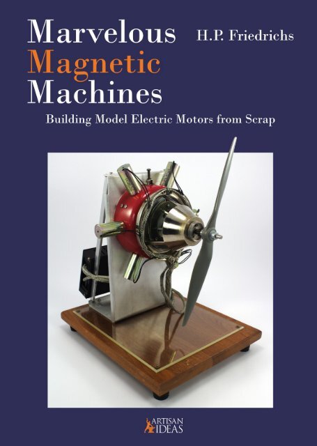
Marvelous Magnetic Machines: Building Model Electric Motors from Scrap
You’re standing in front of an old card table in a driveway at a garage sale. On that table is a one-quart aluminum saucepan, a votive candle holder, pieces of some office machinery, and a wooden awards plaque. What do you see there? If you did not answer “a six-cylinder radial electromagnetic attraction motor,” then you need this book! H.P. Friedrichs (author of The Voice of the Crystal and Instruments of Amplification) returns this time to explore the principles behind the operation and construction of five simple, yet impressive, model electric motors. Aspiring mechanical model makers are often discouraged by their lack of access to machine tools, like mills, lathes, or drill presses. Friedrichs demonstrates that with some basic knowledge, an open eye, and a sharp mind, one can use commonly available (and often discarded) parts and materials to engineer one’s way around any lack of expensive machine tooling. In fact, every motor in this book was built from scrap, and can be assembled with hand tools. You’ll learn where to hunt for and find materials, and where to salvage suitable bearings. You’ll know where useful solenoids can be extracted from scrap, and how to fabricate bobbins to wind your own. You’ll learn how to time your motors, fashion a connecting rod, make a commutator from scratch, use a hall effect sensor to detect magnet position, use a transistor as a switch, and much more. Hardcover, 160 pages,177 photos and illustrations.
You’re standing in front of an old card table in a driveway at a garage sale. On that table is a one-quart aluminum saucepan, a votive candle holder, pieces of some office machinery, and a wooden awards plaque. What do you see there? If you did not answer “a six-cylinder radial electromagnetic attraction motor,” then you need this book!
H.P. Friedrichs (author of The Voice of the Crystal and Instruments of Amplification) returns this time to explore the principles behind the operation and construction of five simple, yet impressive, model electric motors.
Aspiring mechanical model makers are often discouraged by their lack of access to machine tools, like mills, lathes, or drill presses. Friedrichs demonstrates that with some basic knowledge, an open eye, and a sharp mind, one can use commonly available (and often discarded) parts and materials to engineer one’s way around any lack of expensive machine tooling. In fact, every motor in this book was built from scrap, and can be assembled with hand tools.
You’ll learn where to hunt for and find materials, and where to salvage suitable bearings. You’ll know where useful solenoids can be extracted from scrap, and how to fabricate bobbins to wind your own. You’ll learn how to time your motors, fashion a connecting rod, make a commutator from scratch, use a hall effect sensor to detect magnet position, use a transistor as a switch, and much more.
Hardcover, 160 pages,177 photos and illustrations.

You also want an ePaper? Increase the reach of your titles
YUMPU automatically turns print PDFs into web optimized ePapers that Google loves.
10<br />
Chapter 1<br />
Principles<br />
There is a certain logic to the way I set out to build my machines. If you’re not familiar<br />
with the principles on which that logic is based, you may find yourself wondering<br />
why I did what I did. For this reason, it’s worth it to take a few moments to muse on the<br />
subject of magnetism itself. Of course, this is not the book for an in-depth study of the<br />
topic, but that doesn’t mean I can’t draw your attention to a factual nugget or two that I<br />
think will come in handy later.<br />
The Earth as a Magnet<br />
Most humans regard the earth as a large, rocky sphere. In truth, only the very<br />
surface, to a depth ranging <strong>from</strong> a few miles to a few tens of miles, it is composed of rock<br />
in the sense we normally think of it. Beneath the crust is a layer called the mantle, and<br />
below that is the core of the earth. The core itself is composed of at least two layers. The<br />
inner core is a solid, metallic sphere at the very center of the earth, suspended in an outer<br />
core comprised of molten metal, a relationship that reminds me of a cherry cordial. The<br />
core is relevant to our larger discussion, because a so-called “dynamo theory” postulates<br />
that motion in the liquid outer core (or possibly a liquid sub-core within the solid inner<br />
core) is responsible for the creation and long-term maintenance of the earth’s magnetic<br />
field. This field emerges near, but not precisely at, the southern axis of the globe, extends<br />
into space, curves around, and reenters the earth in the vicinity of, but not precisely at,<br />
the northern axis.<br />
This field is sufficiently intense to leave its permanent imprint on certain metallic<br />
rocks and minerals. Rocks containing hematite and magnetite, for example, can be<br />
magnetized by exposure to the earth’s magnetic field. Samples of these materials can<br />
be brought into the lab and analyzed, revealing the history of and changes to the earth’s<br />
magnetic field over many millions of years. At some point in our distant past, people<br />
noticed these magnetic rocks, sometimes referred to as lodestones, and their peculiar<br />
properties. People noticed that lodestones would sometimes stick together, though<br />
sometimes they repelled each other. When iron came into use somebody surely noticed<br />
that bits of iron would cling to lodestones as well.<br />
The first practical use of magnetism was in the construction of an instrument<br />
synonymous with navigation: the compass. If a piece lodestone is suspended <strong>from</strong> a<br />
thread, or placed upon a slab of cork floating in a bowl of water, the lodestone magically<br />
orients itself so as to always come to rest “pointing” in a specific direction. Of course,<br />
what is really happening is that the lodestone is reacting to the earth’s magnetic field, and<br />
aligning itself with respect to that that field.<br />
When I was in school, we were taught that the compass was invented by the<br />
ancient but technologically-advanced civilization of the Chinese. Depending upon what<br />
you’re willing to accept as evidence, this certainly occurred before 1000 A.D., and
maybe as far back as 400 B.C. The discovery of a crafted piece of magnetized hematite,<br />
shaped into a rod-like form, complete with a groove that could be used for sighting the<br />
instrument, has been found in connection with the Olmecs of Mezoamerica. If correctly<br />
interpreted, that artifact has the potential to push the invention of the compass all the way<br />
back to 1000 B.C.<br />
Later, somebody discovered that it was possible to confer the properties of<br />
magnetism onto a previously unmagnetized iron needle by stroking the needle with a<br />
lodestone. This, of course, was useful in the construction of more delicate and sensitive<br />
compasses. It seems the Chinese are credited with this development as well, though I<br />
suspect that, given the magical properties of magnetism, and the experimentation that it<br />
always seems to inspire, knowledge of the properties of lodestones, magnetic materials,<br />
and compasses may have developed independently in numerous places over a wide span<br />
of time. Having watched my grandson in his experiments, and recalling my own, it would<br />
not surprise me if an archaeologist someday proves that much of this early research was<br />
accomplished in play by children.<br />
Pairs of Poles<br />
<strong>Magnetic</strong> poles always exist in pairs. Poles are the terminals <strong>from</strong> which magnetism<br />
flows. A classic way to demonstrate this is to tape a bar magnet to the underside of a sheet<br />
of white cardboard. If the top side of the cardboard is then sprinkled with iron filings, the<br />
particles of iron will arrange themselves according to the magnetic lines of flux as they<br />
exit one pole, curve about, and reenter the other pole. Note that magnetism is not actually<br />
composed of lines, though the effect of the magnetic field on the iron particles develops<br />
an image of flux lines that are useful for visualizing the operation of magnetic circuits.<br />
Television programs like to warn viewers, “Don’t try this at home.” On the contrary,<br />
this is one of those experiments that you really should try yourself, though a helpful<br />
suggestion is in order. Before you begin, seal your magnet inside of a plastic sandwich<br />
bag to protect it. If you should accidentally spill or scatter filings on a naked magnet,<br />
cleaning it can become an exercise in utter futility.<br />
I mentioned earlier that the earth generates a fairly intense magnetic field with<br />
one pole lying at the far North (near, but not at the earth’s axis) and the other in the far<br />
South. The fact that a bar magnet will align itself with the earth’s field in a predictable<br />
way provides a ready means by which the poles of a magnet can be distinguished <strong>from</strong><br />
one another. When the suspended magnet has finally come to rest, the pole pointed toward<br />
the geographic north is identified as the “north-seeking pole” while the other becomes the<br />
“south-seeking pole.” “north-seeking pole” and “south-seeking pole” are wordy phrases<br />
that are usually shortened to “north pole” and “south pole,” respectively. Often a simple<br />
“N” or “S” will suffice.<br />
With two bar magnets, whose poles have been identified by the technique above,<br />
a few moments of play yields one of the most basic of magnetic principles, namely, that<br />
like poles repel, and unalike poles attract. Bring the north pole of one magnet to the north<br />
pole of another, they will repel. Bring the south pole of one magnet to the south pole<br />
of another, they too, will repel. Bring the north pole of one magnet to the south pole of<br />
another, and they will attract each other.<br />
11
Chapter II<br />
The Peewee Motor<br />
Figure 2-1: The Peewee<br />
Motor, front.<br />
No one less than the great chemist and microbiologist Louis Pasteur is said to have<br />
remarked, “Chance favors the prepared mind”. Personal experience says that he<br />
is absolutely correct. My own predisposition to tinker with every piece of electronic or<br />
mechanical scrap I can get my hands on, combined with a chance event, led directly to<br />
the construction of the motor I am about to describe, and by extension, to the creation of<br />
this entire book.<br />
I was at work, and I needed to print something. We have shared printers in our<br />
office, those large combination printer/copier/scanner affairs. I clicked my computer<br />
mouse to send off a print job, and then left my desk to visit the printer and pick up<br />
my paperwork. There, I ran into the fellow who maintains those machines. He had just<br />
finished repairing my printer and was about to toss some kind of part into the waste can.<br />
“May I have that?” I asked. “Why sure,” he said, amused. Handing it to me, he<br />
asked, “What are you going to do with it?” “I dunno,” I answered honestly, “but I’ll think<br />
of something.”<br />
24
The details of that printer component would be irrelevant, if I could even remember<br />
them. The point is that, mounted upon it someplace, was a contraption I recognized as a<br />
solenoid. I removed it, and turned the part around in my fingers. This, I decided, would<br />
form the basis of a nifty little motor I subsequently named the “Peewee Motor”. See<br />
figures 2-1 and 2-2.<br />
Solenoids<br />
In the last chapter, we discussed how to use an electric current to produce a<br />
magnetic field, namely, to pass it through a coil of wire. We also noted that if the coil is<br />
wound upon a suitable material, like iron or steel, the field produced is much stronger.<br />
A useful variation on this idea is to wind the coil on a hollow tube. If we energize<br />
the coil, and then insert a short steel rod into the mouth of the tube, we will observe that<br />
the magnetic field in the interior of the coil will exert a force on the rod so as to draw or<br />
suck it into the interior. Turn off the juice, and the steel rod falls out. This arrangement of<br />
parts, often referred to as a solenoid, has the ability to convert an electrical current into<br />
a linear mechanical force.<br />
Practical solenoids exhibit several enhancements that greatly improve their<br />
performance. Many solenoids feature an external steel frame that wraps around the<br />
exterior of the coil, which helps to further intensify the field produced by the coil. The<br />
bore of the coil may be plugged at one end with a section of steel rod, bonded to the frame.<br />
This is also intended to intensify the magnetism. This is sometimes referred to as a “stop”.<br />
The moving part of the solenoid, referred to alternately as the “armature” or “plunger,” is<br />
composed of materials with a high-μ. The end of the plunger may be machined to a coneshaped<br />
point, and may engage with a similar conical cavity in the previously-mentioned<br />
bore plug. Again, this detail enhances the coil’s effect on the movable plunger, so as to<br />
increase the force with which the plunger is drawn into the core.<br />
Figure 2-2: The Peewee<br />
Motor, rear.<br />
25
Engine Timing<br />
As discussed earlier, proper motor operation depends upon precise timing. By<br />
this, I mean that the solenoid must be activated, and also deactivated according to the<br />
position of the crank and the solenoid plunger. In this motor, the solenoid is turned on and<br />
off with a simple leaf switch. The switch itself is actuated with a cam.<br />
Leaf switches are composed of two or more<br />
strips of springy metal fitted with metal switch<br />
contacts. At one end the metal strips, or leaves,<br />
they are spaced and kept insulated <strong>from</strong> one<br />
another by one or more insulating plates which<br />
are inserted between them. Additional insulating<br />
plates and tubes, held together with screws and<br />
nuts, form a sandwich which completes the switch<br />
assembly. A partially dismantled leaf switch can<br />
be seen in figure 2-8.<br />
Figure 2-8: A partially dismantled leaf<br />
switch. Metal leaves fitted with switch<br />
contacts are clamped in a sandwich<br />
comprised of insulating tubes and<br />
plates.<br />
A wire is attached to each leaf. The free ends<br />
of the metal leaves comprise the business end of<br />
the switch. If you apply a force to the leaves, they<br />
will flex. Apply enough of a force to cause them<br />
to touch one another, and the switch turns on.<br />
Leaf switches are sometimes composed of many, many leaves, which are actuated<br />
in tandem by a toggle or bat handle. In the case of the Peewee Motor, I inherited a damaged<br />
switch in which most of the leaves had been burned and destroyed by a short circuit. I<br />
dismantled the switch, extracted two good leaves, along with some of the insulating<br />
hardware, and built a basic two-leaf switch.<br />
It is a simple matter to fabricate a leaf<br />
switch <strong>from</strong> scratch <strong>from</strong> bits of springy metal.<br />
Hobby brass or shim stock would probably work<br />
well. Consider insulating materials like bits of<br />
Formica, plastic, acrylic, or fiberglass board, cut<br />
<strong>from</strong> a scrapped circuit board. Another option<br />
would be to find a momentary-contact switch with<br />
a paddle or lever arm on it. These are often used<br />
as interlock switches on the lids of printers or the<br />
doors of certain appliances.<br />
My leaf switch was mounted to the<br />
L-bracket, near the crankshaft, using a piece of<br />
aluminum L-channel and a couple of 6-32 bolts and<br />
nuts. Your mounting method may vary, but note<br />
that it is advantageous to allow for some adjustability<br />
with regard to the switch’s exact position.<br />
Figure 2-9: A shaft collar and an<br />
eccentric are soldered together to<br />
produce the Peewee Motor’s timing<br />
cam.<br />
32
The switch is actuated with a cam. In the Peewee Motor, the cam was fabricated<br />
<strong>from</strong> a shaft collar, like the ones used to build up the crank, and a short length of brass<br />
strip. The strip was soldered to the face of the collar. The strip was dressed with a metal<br />
file so that one end matched the circumference of the collar. The other end was allowed<br />
to protrude beyond the radius of the collar, though it was also dressed to remove squared<br />
corners and to give it a graceful, rounded profile. See figure 2-9.<br />
The cam was installed on the crankshaft between the bearing and the crank,<br />
and the switch was adjusted so that, when the cam swept against the leaves, they were<br />
depressed, and the circuit through them was completed. The proper fitting of the switch<br />
and cam is largely a trial-and-error proposition. The lobe projecting <strong>from</strong> the cam should<br />
not be excessively tall, as this is likely to place needless drag on a motor that is not<br />
particularly powerful to begin with. On the other hand, it must be of sufficient height to<br />
positively actuate the switch you are using. In my case, a lobe height of about 0.125-inch<br />
was sufficient.<br />
The last and most critical step is to set the motor’s timing. To do this, I loosened the<br />
set screw on the cam just enough to allow me to twist and adjust its angular position on the<br />
crankshaft, but left it tight enough so that the cam would retain its position when I let go.<br />
Figure 2-10: A view of the crank, cam, and reed switch. For clockwise rotation, the cam leads the crank<br />
by roughly 90 degrees. See text for details.<br />
Motor timing is best expressed in terms of degrees of rotation. The Peewee<br />
Motor was set up to run in a clockwise fashion, as viewed by the crank end of the shaft.<br />
The position of the crank at which the plunger is fully inserted into the solenoid coil<br />
is considered “top dead center”, or zero degrees. In the case of the Peewee Motor, this<br />
means the crank is pointing to the right.<br />
Angular displacement increases as we rotate the crank clockwise. When it points<br />
down, we’ve reached the 90 degree position, to the left is 180 degrees. When the crank<br />
points upward, that’s the 270 degree position. When we’ve completed a revolution of a<br />
full 360 degrees, we’ve returned to the top-dead-center, or 0 degree, position. Figure 2-10<br />
shows the general relationship between the crank, cam, and reed switch.<br />
33
To time the motor, I rotated the crank until it was positioned vertically, at the 270<br />
degree position. Then, I adjusted the cam so that the leaf switch had just closed. Next I<br />
rotated the crank clockwise toward the top dead center position. I verified that the switch<br />
opened back up, just before the plunger reached the point at which it was fully inserted<br />
into the coil.<br />
Again, adjustments here require some tinkering. The point at which the switch<br />
will close is determined by the angular position of the cam on the crankshaft. The amount<br />
of time the switch will remain closed, the dwell time, depends upon the profile of the<br />
cam, and to some extent, the height of the cam’s lobe. In any event, once all of the<br />
adjustments and modifications were made, I tightened the set screw on the cam to lock it<br />
into place.<br />
Testing and Results<br />
The motor was wired according to figure 2-11. Stated simply, the leaf switch was<br />
wired in series with the solenoid, and the leads were terminated with a pair of “banana”-<br />
style binding posts, one red, and one black. The binding posts provide a means by which<br />
a direct-current power supply can be connected to the motor, and are visible at the top of<br />
the motor in figure 2-1.<br />
By convention, the power supply’s positive lead is connected to the red binding<br />
post, while the negative lead is connected to the black. In truth, inverting the polarity of<br />
the power supply (swapping the positive and negative leads) has no effect on this motor<br />
whatsoever. However, in other motors described in this book, a miswired supply can<br />
cause the motor to run in reverse or not at all, so this is a detail worth paying attention to.<br />
Figure 2-11: The wiring for the Peewee Motor is simple. The solenoid and leaf switch are connected in<br />
series and then terminated with binding posts.<br />
Because this motor is of the single “cylinder” reciprocating type, most of the time<br />
it is not self-starting. The flick of a finger against the flywheel will set the machine into<br />
motion. Once in operation, it is entertaining to watch, as the reciprocating parts make<br />
interesting noises when in operation.<br />
34
The solenoid used to build the<br />
Peewee Motor has a label specifying an<br />
operating voltage of 24V, D.C. I have<br />
run the motor on as little as 8V, D.C., and<br />
as high as 30V. Figure 2-12 shows the<br />
relationship between motor speed and<br />
applied voltage. Notice that the motor<br />
tops out around 1000 RPM, after which<br />
further increases in voltage do little to<br />
increase the motor’s speed. This is no<br />
doubt the point where the motive force<br />
of the solenoid on the crank is offset<br />
by parasitic losses in the machinery,<br />
including friction and windage.<br />
Figure 2-12.<br />
Critical Considerations<br />
<strong>Motors</strong> of this type will run in only one direction. If you wish to reverse the<br />
direction that the motor runs, you need to change the position of the cam. Try loosening<br />
the set screw, and rotate the cam 180 degrees <strong>from</strong> its present position. Then tighten the<br />
set screw again. You may need to do some fine tuning.<br />
The crank represents an unbalanced load, because it extends asymmetrically <strong>from</strong><br />
the shaft. Unbalanced loads on rotating parts lead to vibration. Consider, now, that the crank<br />
does not operate in isolation. It’s linked to the solenoid plunger, which reciprocates. The<br />
force of the magnetic field in the solenoid accelerates the plunger <strong>from</strong> a dead stop, and<br />
draws it into the coil, where the plunger then decelerates and comes to a halt. The inertia<br />
of the flywheel and the action of the crank then accelerates the plunger in the opposite<br />
direction, drawing it out of the coil, where it is decelerated to return to its starting position.<br />
At 1000 RPM, this violent sequence must take place in less than six one-hundredths of a<br />
second. The connecting link, being attached, is doing likewise. My point is that the sum<br />
total of all of this imbalance and thrashing to and fro results in a lot of vibration.<br />
In practical reciprocating engines, some of this vibration is suppressed through<br />
the use of counterweights which are typically attached to the crankshaft or the crank<br />
itself. The weights are sized, shaped, and positioned to generate intentional forces that<br />
neutralize, to a large extent, the vibration described above. The Peewee Motor would<br />
probably benefit <strong>from</strong> a counterweight. One way to implement this would be to drill and<br />
tap some holes in the face of the flywheel, where screws could be used to attach washers.<br />
When coils are energized and magnetic fields are created, energy is actually stored<br />
in that magnetic field. If we disconnect power to the coil abruptly, the field collapses, and<br />
the stored energy has to go someplace. Some of the energy is dissipated as heat, while<br />
some reemerges as a voltage “spike,” more properly termed a counter-EMF (Electro-<br />
Motive Force). Evidence of this appears between the contacts of the leaf switch in the<br />
form of bright, hot sparks. Discharges of this type can be rough on switches and will<br />
eventually erode their metal contacts.<br />
35
Figure 2-21: The formula for torque is the product of force times distance.<br />
Figure 2-22 depicts a large wrench affixed to the head of a bolt. The wrench is<br />
2-feet long. A force of 10 pounds is applied to the wrench’s handle. The result is 2 by10<br />
or 20 pound-feet of torque. Note that if the same amount of handle force were applied to<br />
a 4-foot wrench, this would double the torque produced. This mathematical relationship<br />
is why, in the face of a recalcitrant lug nut, some mechanics will employ the tactic of<br />
extending the lug wrench’s handle with a piece of steel pipe.<br />
θ<br />
Figure 2-22: Torque on a bolt head is the product of<br />
the force applied times the length of the lever arm.<br />
Angle theta is presumed to be 90 degrees, but if not,<br />
this has to be accounted for.<br />
By definition, the force is always<br />
applied perpendicularly (meaning,<br />
90 degrees with respect) to the lever<br />
arm. If we apply the force at some<br />
other angle, the resulting torque is<br />
diminished. This can be demonstrated<br />
by decomposing the applied force<br />
vector into two constituent vectors, one<br />
in the direction of the crank handle,<br />
and one perpendicular to it. If we<br />
remember that changing the angle of a<br />
tow rope attached to a box will change<br />
the amount of pulling force on the box,<br />
it makes sense that changing the angle<br />
of the pulling force on a wrench handle<br />
might affect the amount of torque<br />
produced.<br />
Because of this, the full expression for torque includes a sine theta factor (figure 2-23):<br />
Figure 2-23: A torque formula that accounts for the angle of the applied force.<br />
Angle theta represents the angle of the applied force with respect to the lever<br />
arm. If we apply the force in a perpendicular fashion, as is ideal, theta is by definition 90<br />
degrees. The sine of 90 degrees is one, which is then multiplied by the force times the<br />
length of the crank arm to give you torque as defined earlier. On the other hand, if the<br />
force is not applied perpendicular to the crank, theta becomes some number other than<br />
90 degrees. The sine of a theta value greater or less than 90 is a fractional value, some<br />
number less than one. When multiplied by the force and length numbers, the torque value<br />
becomes less than what it would otherwise have been.<br />
40
Cranks, Links, and Angles<br />
If you spin the flywheel of the Peewee Motor with your fingers and watch the<br />
behavior of the crank and connecting link, it immediately becomes apparent that the<br />
angle between the crank arm and the link is constantly changing. This means that the<br />
capability of the solenoid to impart torque on the crankshaft is also constantly changing.<br />
The way these angles change with respect to one another has to do with the length of the<br />
crank arm and the length of the connecting link.<br />
Out of curiosity, I wrote a set of equations to study torque as a function of the<br />
connecting link length. Initially, my equations assumed a crank arm of one unit in<br />
length, a connecting link of one unit in length, and an hypothetical solenoid fired over<br />
the 90-degree period between the 270-degree mark and top dead center. I then plugged<br />
in several different values for the length of the connecting link and plotted the data<br />
to see how torque is affected as the connecting link’s length changes. The results are<br />
summarized in figure 2-24.<br />
Figure 2-24: Connecting link length effects the torque profile of a crank.<br />
If we assume that the force produced by the solenoid is uniform over its entire<br />
stroke, the most efficient conversion of force-to-torque seems to occur when the<br />
connecting link is in the neighborhood of 1.5 to 2 times the length of the crank arm.<br />
All that said, it bears mentioning that the force produced by real solenoids is<br />
typically very non-uniform. Figure 2-25 (adapted <strong>from</strong> Underhill) represents data<br />
collected on an experimental solenoid, similar in features to the solenoid used in the the<br />
Peewee motor. This graph depicts the relative force on the plunger as a function of it’s<br />
stroke.<br />
41
Chapter III<br />
The Texas Motor<br />
Figure 3-1: The Texas<br />
Motor, front.<br />
Amateur Radio is a wonderful and instructive pastime. There is great fun in exercising<br />
the privilege to build, experiment with, and use radio transmitting equipment. Over<br />
the years, I’ve learned an awful lot, and met a lot of nice people. The ham radio fraternity<br />
is one immersed in a rich culture with longstanding traditions. One such tradition is the<br />
so-called “hamfest”.<br />
Hamfests are social gatherings where hams converge to buy, sell, and trade<br />
parts, equipment, and tall tales. Hamfests may be conducted in a community center, the<br />
conference room of a hotel, or in an unoccupied school building on a Saturday, but where<br />
I live, the weather is nice most of the time. Most of the hamfests I’ve attended have been<br />
conducted outdoors, in a parking lot or in an open field.<br />
One never knows what treasure may be found at a hamfest. Sellers cover their truck<br />
beds, tailgates, and folding tables with vintage radio transceivers, old tubes, antenna parts,<br />
recording equipment, computer parts, switches, wire, decommissioned military electronics,<br />
and who knows what else. Prices are often good, and many sellers like to haggle. It’s great<br />
fun for anyone who tinkers with electricity or electronics, ham operator or not.<br />
44
On one occasion, I had visited a hamfest out in Sierra Vista, Arizona. I was<br />
returning to my parked car when I passed a pickup truck with three men in the back. They<br />
were hunched over some old equipment, and were busy pulling vacuum tubes out of it.<br />
“Looks like you found something good,” I said offhandedly, honoring the ham<br />
tradition of friendliness. “We got all of this stuff cheap,” one man answered. “We’re only<br />
interested in the tubes, though.” A light lit up in my head. “What are you gonna do with<br />
what’s left?” “Dumpster, I guess,” the man answered. “Could I have it?” I asked. “It’s all<br />
yours!”<br />
One of the chassis I salvaged <strong>from</strong> these guys was part of an old reel-to-reel tape<br />
recorder. When I got home, I took it apart and extracted fistfuls of useful parts likes nuts,<br />
screws, springs, pulleys, and similar mechanical odds and ends, not to mention a box full<br />
of electronic components. I also extracted a beautiful flywheel, perhaps 3-1/2-inches in<br />
diameter, along with its matching bearings. That flywheel begged me to become part of<br />
a <strong>Marvelous</strong> <strong>Magnetic</strong> Machine, and eventually it did.<br />
The end result is machine I call the Texas Motor. See figures 3-1 and 3-2. Like the<br />
Peewee, this is also an attraction motor, which relies on a crank to convert reciprocating<br />
to rotary motion. The Texas Motor differs <strong>from</strong> the Peewee in that motive force comes<br />
<strong>from</strong> the action of fixed-core coils upon a steel armature. Its most distinguishing feature<br />
is its “walking beam,” a teeter-totter-like mechanism that couples the armature to the<br />
crankshaft. The Texas Motor bears more than a passing resemblance to the pumpjacks<br />
one might see in the oilfields of Texas, and so this is where the motor gets its name.<br />
Figure 3-2: The Texas<br />
Motor, rear.<br />
45
Rather, it was composed of a cylindrical aluminum core, which had been molded into<br />
the interior of the knob. I carefully squeezed the knob in a vise to fracture the plastic,<br />
and extracted the core. The core had two set screws to lock it to any shaft it might have<br />
been installed on. In this sense, it was not<br />
unlike one of the shaft collars I introduced<br />
in Chapter 2, only much, much larger<br />
— about 1-inch in diameter. Figure 3-4<br />
depicts the parts that were extracted <strong>from</strong><br />
the instrument knob, looking <strong>from</strong> the<br />
front.<br />
Figure 3-5: Radio dial components, <strong>from</strong> the<br />
rear. Note how the graduated dial plate fits to the<br />
shoulder of the core and is clamped in place by the<br />
retainer plate and screws.<br />
The rear face of the core, the end to<br />
which the graduated dial had been affixed,<br />
had a stepped contour or “shoulder”<br />
cut into it. This diameter, somewhat<br />
less than the 1-inch outside diameter of<br />
the cylinder, fit into a large hole in the<br />
center of the aluminum dial plate. The<br />
dial screws, when tightened, forced a<br />
retaining plate against the graduated<br />
dial plate, effectively clamping it to the<br />
shoulder on the cylinder. This relationship is more evident <strong>from</strong> Figure 3-5.<br />
Two modifications rendered the core suitable for use as a crank. First, I drilled<br />
out the bore of the core to 8 millimeters, so that it would slide onto the crankshaft of my<br />
motor. Next, I noted that the holes into which the dial-retaining screws had been threaded<br />
had been bored and tapped all the way through the cylinder <strong>from</strong> one face to the other.<br />
To create a crank handle, I located a 6-32 bolt, a couple of washers, and 1/4-inch diameter<br />
steel standoff. I inserted the bolt through the washer and the standoff, and then threaded<br />
the end of the bolt into one of the holes in the aluminum cylinder. This resulted in a crank<br />
with a 1/2-inch throw.<br />
Figure 3-6: The modified radio dial. A 1/4-inch round standoff is affixed to the face of the core to create<br />
a crank. The graduated dial plate has been cut and filed to an eccentric shape to form a cam.<br />
Further, I reasoned that if I cut down the graduated dial plate, filed it into an<br />
eccentric, and then reinstalled it on the aluminum core as the dial had originally been,<br />
I could use this as a cam by which to time the motor’s firing. The fact that the cam was<br />
48
clamped into place would mean that the angle between the cam and the crank could be<br />
changed simply by loosening the screws in the retaining plate, and that the angle between the<br />
cam and crank was infinitely and precisely adjustable. The modified radio knob hardware,<br />
better illustrated than explained, can be understood by studying figure 3-6.<br />
Two additional advantages arise <strong>from</strong> this design. First, by combining the crank<br />
and cam into one unit, the combined assembly is smaller and occupies less space on the<br />
crankshaft. Second, it becomes possible to dismantle the motor and remove the crankshaft<br />
without upsetting the timing relationship between the crank and the cam.<br />
Admittedly, the odds of another builder finding the same kind of junked radio knob<br />
that I used in this adaptation is pretty slim. Nonetheless, there is merit in presenting the<br />
design because there are endless alternatives. Other radio or instrumentation knobs may<br />
have similar internal parts, or unrelated scrap could be used to replicate the pieces I just<br />
described.<br />
Coils and Backstrap<br />
As I’ve indicated, I like variety in my motors. So where the Peewee Motor makes<br />
use of a commercially manufactured, hollow-core solenoid assembly (acting upon a<br />
movable plunger), the Texas Motor generates its operating forces with a pair of homemade<br />
fixed-core electromagnets which act upon an armature in the form of an attraction plate.<br />
The basic form of the coil assembly is U-shaped, and can be seen in figure 3-7.<br />
The base of the electromagnet assembly — the back strap — was cut <strong>from</strong> a piece<br />
of 0.125-inch (1/8-inch) steel strap, procured at a local hardware store. The steel measures<br />
about 5-inches in length and 0.75-inch in width. I drilled four holes in it.<br />
Two of the holes were drilled large enough to pass a #8 bolt, and were later used<br />
to fasten the back strap to the motor base. The holes are located about 0.375-inch (3/8-<br />
inch) <strong>from</strong> each end of the strap. When bolted<br />
to the base, the back strap rests upon a couple<br />
of standoffs, which raises it above the surface of<br />
the base about 0.625-inch.<br />
The other two holes in the back strap<br />
are just over 1/2-inch in diameter, large enough<br />
to pass the 1/2-inch steel bolts which are used<br />
as cores for the electromagnets. Measured <strong>from</strong><br />
center to center, the holes for these bolts are<br />
spaced 1.875-inches apart, and are centered on<br />
the strap.<br />
The bolts used for the coils’ cores are<br />
each 2-1/2-inches long. Each core is anchored to<br />
the back strap with a pair of 1/2-inch nuts. The<br />
heads of the bolts face upward, and become the<br />
pole faces for the finished electromagnets.<br />
Figure 3-7: Coils wound on bobbins,<br />
½-inch bolt cores, and the steel backstrap.<br />
49
Figure 3-13: A discarded potentiometer contains numerous parts. The potentiometer’s threaded shaft<br />
bushing can be recycled to make a smooth-running bearing for small machines like motor models.<br />
A bit of creative demolition with a small flat-blade screwdriver, a file, and perhaps a<br />
hobby grinding tool, is all it takes to open the pot’s body. This allows for the removal of the<br />
shaft and the pot’s internals, and for the extraction of the bushing. Older American-made<br />
pots typically feature 1/4-inch shafts, which means that the bushing has a 1/4-inch bore. It is<br />
one of these pot bushings that I re-purposed as a bearing for the walking beam.<br />
Using scrap aluminum, I fashioned<br />
two L-brackets. I bored a hole in each one,<br />
large enough to fit the bushing. I installed<br />
the bushing on one of the L-brackets, and<br />
fastened it with the matching bushing nut.<br />
I added a second nut, just to occupy space,<br />
and then added the second L-bracket. The<br />
latter is held in place with a third nut. The<br />
completed assembly can be seen in figure<br />
3-14. Note how the legs of the L-brackets<br />
point in opposite directions, providing a very<br />
stable base for the bearing and a convenient<br />
surface by which to mount the assembly onto<br />
another surface.<br />
Figure 3-14: The beam bearing assembly<br />
is comprised of two L-brackets, a threaded<br />
bushing and three nuts.<br />
Recall that the spacers which bond the two halves of the beam together are round,<br />
and 1/4-inch in diameter. The spacer at the fulcrum point will fit perfectly inside of the<br />
bearing I just described and will rotate smoothly. Obviously, one must insert this spacer<br />
into the bearing before bolting it into place in the beam assembly.<br />
The walking beam sits about 6-inches above the base of the motor. It’s supported<br />
in this elevated position atop a “gallows-like” arrangement, that is to say, two legs and a<br />
bridge-piece. The legs are aluminum hex standoffs, threaded for #8 screws. Alternately,<br />
you could probably use sections of metal tubing or short brass or steel pipe nipples.<br />
56
The bridge is fashioned <strong>from</strong> a 3-1/2-inch section of 0.75-inch (3/4-inch) aluminum<br />
angle. It provides a shelf upon which the fulcrum bearing assembly is mounted. I drilled<br />
holes through the “feet” of the bearing assembly, and corresponding holes in the gallows’<br />
bridge. The bearing is attached to the bridge with two 6-32 bolts and nuts. The gallows<br />
assembly can be seen in figure 3-15.<br />
Figure 3-15: The beam bearing assembly<br />
sits atop a gallows-like structure, comprised<br />
of hex standoffs and a bridge. In this image<br />
the walking beam is shown installed, as well.<br />
Connecting Rods<br />
The Texas Motor uses two connecting rods. One is dog-bone-shaped, with a coupler<br />
at each end, and is used to link the crank to the walking beam. The other connecting rod is<br />
used to link the walking beam to the attraction plate, so it has a coupler at only one end.<br />
The couplers at the ends of the connecting rods were fashioned <strong>from</strong> shaft collars.<br />
The bore of the shaft collars used is 0.25-inch, so they will fit on the crank and the round<br />
standoffs at the ends of the walking beam. The hole in the collar where the set screw would<br />
normally go was drilled out and re-tapped for a 6-32 thread. Into this hole, I threaded a steel<br />
hex standoff. This particular standoff had a 6-32 stud at one end, and a 6-32 threaded hole<br />
at the other. One could use a standoff with two female ends, but one end would have to be<br />
fitted with a section of threaded rod to act as a stud. Details of the connecting rods can be<br />
seen in figure 3-16.<br />
The stud on each standoff, even<br />
when fully tightened into the shaft<br />
collar, does not penetrate into the bore of<br />
the collar. I achieved this through some<br />
trial-and-error, removing the standoff<br />
<strong>from</strong> the collar, carefully dressing the<br />
stud on the standoff with a file, and then<br />
reinstalling it to check for interference.<br />
The body of each connecting<br />
rod is nothing more than a length of<br />
6-32 threaded steel rod. The couplers<br />
are attached to the ends of the rod by<br />
screwing them on.<br />
Figure 3-16: Connecting rods. At left, the connecting<br />
rod for the attraction plate. Center, the connecting<br />
rod for the crank. The detail at the right shows how<br />
the ends of the connecting rod may be fashioned <strong>from</strong><br />
a shaft collar and hex standoff.<br />
57
Connecting rods made in this fashion have several desirable attributes. They<br />
are cheap and simple to make, they run well with reasonably low friction, and they’re<br />
compliant. In addition, their length can be adjusted over a limited span by advancing or<br />
backing off the standoffs on the threaded rod. This can be very useful when trying to finetune<br />
the Texas Motor.<br />
Wiring and Engine Timing<br />
As is always the case, the Texas Motor relies on proper timing to establish just<br />
when the coils of the electromagnets are to be energized. Like the Peewee, the magnets in<br />
the Texas Motor are fired with a leaf switch, and the basic principles with regard to timing<br />
apply here, as well. However, there are a few details unique to the Texas Motor.<br />
The first consideration has to do with coil polarity. Recall that the polarity of the<br />
field produced <strong>from</strong> the poles of an electromagnet depends upon the direction in which<br />
electrical current circulates through the electromagnet’s windings. The pair of coils in the<br />
Texas Motor are able to exert the most aggressive force on the attraction plate only if the<br />
magnetic polarity of their respective cores is different. In other words, when energized,<br />
one core should produce a north magnetic pole, while the other should be a south pole.<br />
With care, I could have recorded the direction with which each coil was wound,<br />
noting which lead of the coil fed the center, and which was connected to the outermost<br />
winding. With this information, I could have predicted what the pole polarity would be<br />
for any given current applied to the windings.<br />
A simpler method is to prepare the coils without regard to polarity, and then<br />
characterize them later. This can be done with a flashlight cell and a cheap magnetic<br />
compass. To do this, I connected the leads of one of the coils to the flashlight cell and<br />
brought the compass near the pole face. The compass needle is either attracted to or<br />
repelled by the field produced in the coil. I swapped the leads on the cell, as needed,<br />
until I observed that the compass needle was repelled, meaning that the pole of the<br />
electromagnet had assumed a north magnetic polarity. When this condition was achieved,<br />
I labeled the coil lead which was attached to the positive terminal of the cell with a piece<br />
of tape. I repeated this same process with the second coil.<br />
Figure 3-17: Wiring for the Texas Motor. The dots near the coils signify the coils are wired to produce<br />
opposite polarity. A capacitor is used to suppress arcing at the switch contacts. See text for details.<br />
58
The coils in the Texas Motor are connected in parallel. However, since we want the<br />
magnetic polarity of the two coils to be different, it follows that the electrical connections<br />
for one of the two coils must be inverted. This is evident in the wiring diagram in figure<br />
3-17.<br />
The Texas Motor’s leaf switch was mounted on the floor of the L-bracket that<br />
supports the crankshaft bearing and flywheel. Details of this can be seen in figure 3-18.<br />
Figure 3-18: Crank,<br />
cam, and leaf switch<br />
detail.<br />
Proper timing for the Texas Motor was established experimentally. The motor was<br />
set up to run counter-clockwise, as viewed <strong>from</strong> the crankshaft end. If we consider top dead<br />
center — the position at which the attraction plate is closest to the coils — as zero degrees, the<br />
timing cam on the Texas Motor was finally adjusted to fire the coils at around 210 degrees.<br />
Testing and Results<br />
Like the Peewee Motor, the Texas Motor is not self-starting. That said, it exhibits<br />
a fair amount of torque for a simple attraction motor. It will sometimes start by itself if<br />
the motor happens to have come to rest with the leaf switch in the closed position.<br />
In operation, The Texas Motor has all the charm of the Peewee Motor, and then<br />
some. Being more complex, mechanically speaking, and larger to boot, there is simply<br />
more to see. It makes a very pleasing sewing-machine-like sound when in operation.<br />
This motor seems “happiest” when running at 24V. The stall current (I) for each coil (leaf<br />
switch on, but flywheel not turning) is dictated by Ohm’s law. See figure 3-19.<br />
Figure 3-19: Stall current is computed by using Ohm’s law.<br />
The stall current for each coil is 24V divided by 66Ω, which works out to be<br />
0.36A, plus some change. The stall current for both coils, is 0.73A. That represents a fair<br />
amount of power (more than 17W), and is likely to overheat and burn up the coils if left<br />
in that state for very long.<br />
59
62
63
Chapter IV<br />
The Christmas Motor<br />
Figure 4-1: The Christmas<br />
Motor, front.<br />
One of the recurrent problems with attraction motors, as represented by the Peewee<br />
and Texas motors, is the fact that they are inherently non-self-starting. This is easily<br />
understood if we consider the operation of the cam and leaf switch in the Texas Motor,<br />
for example. Note that the switch is only on for about 60 degrees of any complete rotation<br />
of the flywheel.<br />
Suppose I were to give the flywheel of an un-powered Texas motor a random<br />
spin, like the proverbial “wheel of fortune”. Since the leaf switch is activated only 60<br />
degrees out of a possible 360, the odds of the flywheel coming to rest with the switch in<br />
the “on” position is only one in six. More important to the point, for any given throw of<br />
the wheel, there is an 83% likelihood that the flywheel will not come to rest in a position<br />
where the leaf switch is on. An “off” switch means no power to the coil, and no power to<br />
the coil means no starting torque.<br />
64
Therefore, if we kill the power to a running Texas Motor, let the flywheel come<br />
to rest, and then reapply the power, the odds are very much against us with regard to the<br />
possibility that the motor will restart by itself. For a model motor, of course, this is no<br />
big deal. All you’ve got to do is give the flywheel a little “kick” to set things into motion<br />
again, but for someone with an engineer’s mind, this trait is inherently annoying.<br />
Now, we could certainly change the cam profile to lengthen the dwell time of the<br />
switch, but the most you can do this is 90 degrees. Beyond that, an “on” coil no longer<br />
contributes to torque, but begins to detract <strong>from</strong> it.<br />
Suppose, however, we expanded the crank, added more solenoids, plungers, and<br />
connecting rods, and distributed them so that the “on” periods of their respective coil<br />
switches overlapped. In that case, for any given rest position of the flywheel, at least one<br />
switch would be on, and at least one solenoid would be positioned to exert torque on<br />
the crank when power to the motor was switched on. An attraction motor of this design<br />
could, in fact, be self-starting.<br />
By definition, a motor of this type is significantly more complex than the Peewee<br />
and Texas motors combined, because of all of the additional moving parts. Then, too, one<br />
must give careful consideration to the matter of topology. How many electromagnets will<br />
be employed, how will they be laid out, and how can one fashion the complex crankshaft<br />
that is needed?<br />
After much thought, I decided to adopt a design reminiscent of old-fashioned<br />
aircraft-style radial engines. My design features six solenoids acting on a common crank.<br />
Figure 4-2: The Christmas<br />
Motor, rear.<br />
65
I take pride in the design because, despite having seen endless examples of model<br />
electric motors in books, magazines, and on the Internet, I have yet to see one built quite<br />
like this one.<br />
It took a lot of scrounging in resale shops, garage sales, and garbage cans to find the<br />
parts I needed and to conceive of the ways in which the constituent junk could be stitched<br />
together. After a lengthy development period, I finally finished the motor a few days before<br />
Christmas one year, hence the name, the “Christmas Motor.” See figures 4-1 and 4-2.<br />
The Solenoids<br />
Motive force for this motor is provided by a set of six solenoids. In the interest of<br />
symmetry and balance, I decided early on that it would be beneficial if I could locate six<br />
identical solenoids. This can be difficult if one is relying entirely on cast-offs and junk<br />
to provide the necessary parts. Electronics surplus houses should not be overlooked as<br />
excellent sources of motor materials. A few minutes on-line located numerous sources of<br />
cheap solenoids, including the ones I ultimately ordered for use in the Christmas Motor.<br />
The solenoids I ended up purchasing were, <strong>from</strong> what I gather, originally<br />
manufactured for a well-known maker of printers and photocopiers. They’re cylindrical,<br />
encased in a metal can or housing, and measure 2-inches long by 1-inch in diameter. The<br />
plunger is black steel, just under 2-1/2-inches in length, and 0.437-inch in diameter. The<br />
end is slotted and drilled to allow a connecting link to be secured to the plunger with a<br />
drift pin. This coil has a long stroke, possibly as much as an inch. See figure 4-3.<br />
One of the more interesting attributes of<br />
this solenoid is its mounting method. Rather than<br />
rely on mounting holes for screws, the mouth of<br />
the solenoid features a large threaded bushing.<br />
The solenoid is designed to be inserted through<br />
a hole in a sheet-metal surface, and secured with<br />
a lock washer and nut. This is almost made-toorder<br />
for the design I had in mind.<br />
Figure 4-3: Solenoid, plunger, and<br />
mounting hardware.<br />
The electrical resistance of the coil measures<br />
around 45Ω, and the part was designed for 24V<br />
service. Yet, in experimenting with the part on the<br />
workbench beforehand, I noted that with as little<br />
as 6V applied, I could detect meaningful pull on<br />
the plunger with it extracted as much as 1/2-inch.<br />
The specific part I used, for the record, is a Solen 121E18711. They were<br />
purchased online for less than $2.00 each, a very small price to pay to acquire a matched<br />
set of identical solenoids. The surplus vendor I acquired them <strong>from</strong> no longer has them<br />
in stock, though a subsequent search of the Internet shows that other suppliers do. It’s no<br />
matter in any event because there are, no doubt, a hundred other surplus coils that could<br />
be pressed into service.<br />
66
The Crankcase<br />
Having decided on a radial-engine design for the Christmas Motor and having<br />
acquired a matched set of solenoids, my next action item was to identify something that<br />
would service as a suitable crankcase. After visiting all of the second-hand and thrift<br />
stores in my area over the course of two or three weekends, I finally happened upon a<br />
church rummage sale at which I discovered the perfect component: a one-quart aluminum<br />
saucepan. The pan cost me twenty-five cents.<br />
The pan I found is 6-inches in diameter and 2-1/2-inches deep. The exterior of the<br />
pan sports a red coating of some kind, a feature that saved me the trouble of having to<br />
paint the motor later. The handle of the pan was broken. This was of no consequence to<br />
me, as I simply backed out its screw and threw it away.<br />
I wrapped a narrow strip of paper around the exterior of the pan and then carefully<br />
marked the paper with a pencil to record the pan’s circumference. Then, with the paper<br />
lying flat on my bench, I measured that circumference with a rule, and divided that length<br />
into six equal segments. I made pencil marks on the paper to denote these divisions.<br />
When I wrapped paper around the pan once more, the marks I had made on the paper<br />
indicated precisely how the solenoids should be distributed. I used a permanent ink pen<br />
to transfer the marks <strong>from</strong> the paper to the walls of the pan itself.<br />
Figure 4-4: The Christmas motor’s<br />
saucepan crankcase showing the<br />
installation of the solenoid bodies.<br />
The three hexagonal parts bolted to<br />
the wall of the saucepan form the<br />
motor mounts. These are discussed<br />
in more detail later.<br />
Accounting for the space that the crank would ultimately consume near the floor<br />
of the pan, I elected to set the row of solenoids so that their centers lay 1-inch off the open<br />
mouth of the pan. I used a rule to make this measurement, and where this 1-inch target<br />
depth intersected the pen marks I made earlier, I dimpled the metal with a punch. This<br />
activity produced six equally-spaced punch marks denoting where mounting holes would<br />
be drilled.<br />
The diameter of the threaded bushing at the mouth of my solenoids was such<br />
that each mounting hole had to be 3/4-inch in diameter. Aluminum is a very easy-to-work<br />
material, so there is more than one way to make holes of this size. My recommendation<br />
is to use a step drill bit.<br />
67
Ball bearings sometimes appear in appliances and tools. Look for them in scrapped<br />
drill motors, old blenders or hand mixers, or hobby grinding tools. Old floppy and hard<br />
disk drives (the older, the better) are another option. Junked tape recorders, printers,<br />
plotters, and photocopiers represent yet other possibilities.<br />
Like solenoids, bearings can be purchased, either brand-new, or surplus. New<br />
units are available on the Internet, though bearings comparable to the ones I used run<br />
about ten or twelve dollars apiece. Some hardware stores, the kind that have chests of<br />
drawers with parts, often stock small bearings, too. At least one hobby shop in my area<br />
carries them, for radio-controlled vehicle use, and their prices are significantly cheaper<br />
than other sources.<br />
One source of bearings that I find very promising is the local toy store. Skateboards<br />
and in-line roller skates use very high-quality ball bearings. Replacements for these<br />
bearings are readily available and can be extremely cheap. Although they’re typically<br />
sold in sets, the per-unit cost can work out to be as little as a dollar apiece.<br />
It is worth noting that the proliferation of inexpensive 3-D printers—whose<br />
mechanisms rely heavily upon ball bearings, polished metal shafts, sprockets, belts, shaft<br />
collars, couplers and similar machine parts—has driven down the price of these types<br />
of components, especially when ordered <strong>from</strong> sources overseas. Fire up your favorite<br />
internet browser and go see what you can find. If you do go this route, be prepared to<br />
work with metric dimensions only.<br />
The Crank and Counterweight<br />
The crank design used in the Christmas motor is based on a piece of hardware<br />
called a shaft coupler. A shaft coupler is similar in principle to a shaft collar, but it’s much<br />
longer, and features not one but two set screws, one near each end. Using this device, one<br />
can insert a short shaft into each end, tighten their respective set screws, and thereby join<br />
two shafts into one, longer shaft.<br />
The shaft coupler used in the Christmas Motor, as most of the pieces and parts<br />
in my motors, was salvaged <strong>from</strong> scrap. It has a 1/4-inch bore, and is 1/2-inch in diameter.<br />
They’re available for sale new and as surplus, but a part like this is easily made <strong>from</strong><br />
scratch, using a segment of a 1/2-inch steel bolt for the body.<br />
Figure 4-8: The Christmas Motor<br />
crank. To the left, the finished article<br />
including the counterweight. To the<br />
right, an exploded view showing<br />
constituent parts.<br />
70
Figure 4-8 shows how the crank was fashioned. I began with the shaft coupler,<br />
and soldered to it a section of 1/4-inch rod which forms the handle of the crank. Two end<br />
plates, cut and shaped <strong>from</strong> strips of hobby brass, were used both to add physical strength<br />
to the assembly, and to assure that the axis of the coupler and the axis of the crank handle<br />
were parallel. To assure proper alignment during fabrication, I temporarily inserted a<br />
stainless steel bolt through the end plates and coupler and fitted it with a nut to clamp<br />
everything together. This stabilized the parts during the soldering operation.<br />
The bottom plate has an extended arm, about 2-3/4-inches long. The end of this<br />
appendage provides a mounting point for a small stack of washers that are used as a<br />
counterweight—an attempt of mine to provide balance and to suppress vibration when<br />
the crank is in motion.<br />
The 1/2-inch diameter of the shaft coupler, combined with the quarter-inch diameter<br />
of the crank handle, results in an overall crank throw of 3/4-inch. When coupled to the<br />
solenoid plungers through a connecting link, this represents a stroke that is well within<br />
the 1-inch capability of the solenoids I used.<br />
The crankshaft itself is a length of 1/4-inch steel rod. It fits into the shaft coupler that<br />
comprises the body of the crank, and is secured by tightening the set screws in the coupler.<br />
For development purposes, I initially used a crankshaft that was far too long. After I had<br />
fitted the crank in the crankcase, and allowed for enough shaft length to account for spacers,<br />
shaft collars, and the attachment of a propeller to the front of the machine, I marked the<br />
shaft, removed it <strong>from</strong> the machine, and cut it to size with a hacksaw.<br />
The Crank Hub and Connecting Links<br />
The trick, in any radial engine, is to contrive a way in which all the pistons, or in<br />
this case, solenoids, can act on a single crank. No part of the Christmas Motor required<br />
more thought and planning than this one, and yet, it’s ultimately simple in principle and<br />
easy to fabricate. Figures 4-9 through 4-16 help to clarify how it was that I fashioned the<br />
parts I needed.<br />
Figure 4-9: Laying out a<br />
hexagonal pattern of holes.<br />
(a) Scribe a circle of desired<br />
size with a compass. (b) Set<br />
the compass point on the<br />
circle at a desired starting<br />
point, and scribe an arc.<br />
Do not change the compass<br />
setting! (c) Move the point<br />
to the intersection of arc and<br />
circle. (d) Repeat the process.<br />
71
The pinning process was repeated until all six connecting links had been pinned<br />
to the crank hub. Note that it may be necessary to trim the link pins for length. If they<br />
protrude too far, there is always the danger that they may interfere with the motion of the<br />
crank, which operates in the space below.<br />
Now, if you’ve been paying attention, you must surely wonder what keeps the<br />
link pins <strong>from</strong> falling out. Good question. The answer lies in the fabrication of a third<br />
disk, a retaining disk. This has the same diameter as the first two, with a single large hole<br />
at the enter, but without all of the other little holes. In essence, it’s nothing more than<br />
a fender washer. I placed it on the bushing, and secured it with the last nut. With this<br />
retainer in place, the pins can jiggle and even back out of their holes a little bit, but they<br />
can’t fall out because the disk keeps them <strong>from</strong> backing out all the way.<br />
For what it’s worth, I took the added step of cutting out a cardboard ring or<br />
“doughnut” to fit underneath the retainer disk. It takes up all of the available “slack”<br />
between the heads of the link pins (finishing nails) and the retainer disk, eliminating inand-out<br />
jiggle in the link pins entirely. Figure 4-14 is a more elaborate exploded view of<br />
the hub assembly, showing the addition of the pin retaining plate and cardboard ring. A<br />
final lockwasher and nut holds the whole thing together.<br />
Figure 4-14: More hub detail. A brass disk, cardboard spacer ring,<br />
lockwasher and nut provide a means by which the link pins are retained<br />
and complete the hub assembly.<br />
With the hub completely assembled and the connecting links in place, I slid the<br />
crank hub onto the end of the crank. To keep the hub <strong>from</strong> falling off of the crank handle,<br />
I installed a 1/4-inch shaft collar.<br />
The free ends of each of the connecting links were inserted into the clevis (slot) at<br />
the end of each solenoid plunger, and pinned into place with a cotter pin. I have found that<br />
if the clevis at the end of the plunger is much wider than the thickness of the connecting<br />
link, you may experience some mechanical slop as the link slides to and fro. In this case,<br />
it’s prudent to add some washers to take up the slack. All of this can be seen in figure 4-15.<br />
I have described the construction of the hub and the attachment of the connecting<br />
links to reflect a progression of thought. There is, however, an essential detail that I<br />
omitted and must now bring to your attention in order for this machinery to work properly.<br />
74
If all of the connecting links are free to swivel at their point of attachment to<br />
the crank hub, there exists the probability that, when forces are applied to the hub by<br />
the solenoids, instead of moving the crank, the hub will simply rotate and “wind up”<br />
around the crank handle. This condition is prevented, in every radial engine I’ve seen, by<br />
assigning one of the connecting links the role of “master” link. As we’ve seen, the master<br />
link in this engine is different <strong>from</strong> the other five links in that it is somewhat longer and<br />
features two holes at the hub end.<br />
Hopefully this revelation sheds some light on the purpose of that “extra” hole in<br />
the hub disks. The master, when pinned to the hub, actually receives two pins, so that it’s<br />
effectively locked to the hub and cannot swivel. The rigid connection between hub and<br />
master link prevents undesired rotation of the hub. Take a closer look at figure 4-14, and<br />
look for the double-pinned master link.<br />
With the parts fabricated and installed as described, including the double-pinned<br />
master link, I could twirl the crank shaft with my fingers and the plungers would dance<br />
inside the crankcase.<br />
The Base, Motor Stand, and Motor Mounts<br />
Radial motor models, particularly when<br />
fitted with propellers, look like they belong on<br />
the nose of an airplane. As I had no intention<br />
of building a matching airframe, I fashioned<br />
a motor stand to support the Christmas Motor<br />
for display and operation. The motor stand is<br />
an L-shaped affair made <strong>from</strong> a 0.125-inch (1/8-<br />
inch) scrap aluminum panel.<br />
I used a machinist’s square and an ink<br />
pen to mark a line where I intended to bend the<br />
panel. I clamped a hardwood block on either<br />
side of the panel, adjacent to the ink line, and<br />
loaded the whole affair into my bench vise.<br />
As I applied force to the free end of the panel<br />
with my hands, the hardwood blocks acted like<br />
a sheet metal brake and allowed me to make a<br />
clean, 90-degree bend.<br />
The motor stand is 12-inches high,<br />
6-1/2-inches wide, and has a foot that’s 4-1/2-inches<br />
long. Because the crankshaft mechanism in<br />
this motor is a real thing of beauty, it seemed a<br />
shame to me that it would be hidden inside of<br />
the crankcase. For this reason, I cut a 2-1/2-inch<br />
diameter hole in the face of the motor stand,<br />
and fitted to it the metal bezel and glass <strong>from</strong> a<br />
discarded air pressure gauge.<br />
Figure 4-15: Plungers are secured to the<br />
connecting links with cotter pins. Washers<br />
can be used to take up the “slop” if the gap<br />
in the tail of the plunger is too wide. The<br />
solenoid plungers ride in the bore of the<br />
solenoid bodies. While this image depicts<br />
the mechanism without the crankcase for<br />
the sake of clarity, the actual assembly of<br />
these components must take place inside of<br />
the crankcase.<br />
75
When using multiple magnets, an important factor to consider is their polarity.<br />
In my case, I arranged my magnets so that one magnet presented a north magnetic pole<br />
to the reed switch, the other magnet presented a south pole. I found that this resulted in<br />
greater reed switch sensitivity and more aggressive switch closure.<br />
Remember that where magnets are concerned, like poles repel, while unalike<br />
poles attract. Knowing this, and with a moment of idle play, you can easily determine<br />
how to orient the magnets on the bracket so that their poles will differ. Alternately, you<br />
can use a magnetic compass to positively identify the polarity of any magnet pole. The<br />
pole of the magnet that deflects the north-seeking end of the compass needle must, by<br />
definition, also be a north seeking magnetic pole.<br />
Needless to say, the angular position of the L-shaped magnet holder on the<br />
crankshaft is not arbitrary. It must be adjusted to trigger the firing of each solenoid at the<br />
proper time. Let your experience with the Pee Wee and Texas motors be your guide.<br />
Coil Drivers<br />
One might assume that, having reached this point, the description of the Christmas<br />
Motor must be nearly complete. After all, we have a bank of solenoids mechanically<br />
linked to a common crankshaft, and a set of switches with which to activate them. Surely,<br />
now, it’s just a matter of wiring each reed switch to its respective solenoid and adjusting<br />
the rotating magnet’s position to set the appropriate timing. Almost true... but not quite.<br />
We’ve seen in prior chapters that solenoid coils can draw a fair amount of current.<br />
At a DC resistance of 45Ω, the solenoids used in this motor, when powered <strong>from</strong> a 24V<br />
supply, will draw more than 0.5A. Based on the operation of the Peewee and Texas<br />
motors, we also know that the collapse of the magnetic field in a solenoid is prone to<br />
cause arcing at the switch contacts.<br />
Reed switches are delicate devices. While there are exceptions, most reed switches<br />
are simply not robust enough to tolerate this kind of abuse. Exceed their current rating,<br />
or subject them to any significant arcing, and the internal contacts are rapidly destroyed.<br />
What is needed is an interface of sorts, something that allows the reed switch to<br />
control the solenoid without having to drive it directly.<br />
One way to implement this idea is with a relay. A conceptual example of the<br />
circuit can be seen in figure 4-21. The relay here consists of a small coil associated with<br />
a robust set of switch contacts. When the reed switch closes, battery power is applied to<br />
the relay coil. The relay coil generates a magnetic field, which attracts an iron armature.<br />
The movement of the armature closes the relay’s switch contacts. When these contacts<br />
close, power is applied to the solenoid.<br />
The reason this scheme is advantageous is because the relay coil requires far less<br />
energy to fire than the solenoid. Adding the relay limits the electrical burden imposed<br />
upon the reed switch. The reed switch tells the relay when to close, but the relay does all<br />
the hard work.<br />
80
Figure 4-21: When the reed switch<br />
is triggered, current flows to activate<br />
the relay. The relay contacts close,<br />
activating the solenoid. The reed<br />
switch is the controlling element;<br />
the relay assumes the more difficult<br />
task of powering up the solenoid.<br />
A big disadvantage of the relay is its electromechanical nature. It contains moving<br />
parts which click and clatter every time the relay is engaged and released. Ultimately, it<br />
wears out. Even if a relay is good to a half-million cycles, a solenoid motor running at<br />
1000 RPM will consume that relay’s advertised life in just over eight hours.<br />
Reliability can be greatly improved if we replace the relay with a transistor.<br />
The transistor is an electrical component that acts as an amplifier. Wired correctly, it<br />
can be made to function as a relay. It has no moving parts, so as long as its electrical<br />
specifications are not exceeded, there is no practical limit on its lifespan. Figure 4-22<br />
depicts the relay circuit of figure 4-21 revised to use a transistor. Again, this specific<br />
design is more conceptual than practical. You’ll see why in just a moment.<br />
Figure 4-22: In this case when<br />
the reed switch is triggered, it<br />
directs current into the base (B) of<br />
the transistor. The presence of a<br />
base current causes the transistor<br />
to switch on, effectively shorting<br />
the emitter (E) and collector (C)<br />
terminals together. This permits the<br />
flow of current through the solenoid.<br />
The transistor has three terminals, an emitter, a base, and a collector. I’ve used the<br />
letters E, B, and C to identify the terminals in the diagram. In this application, the emitter and<br />
collector can be considered as a set of contact points which are used to energize the solenoid.<br />
The base terminal is the input, and is connected to the reed switch. When the reed switch<br />
closes, current flows into the base, which activates the transistor. This causes the collector and<br />
emitter to be electronically joined together, allowing current to flow through the solenoid. The<br />
amplifying capability of the transistor means that a very small current flowing into the base,<br />
perhaps 10 milliamperes, can trigger a current in the solenoid that’s 50 or more times greater.<br />
Roughly speaking, there are two classes of transistor, designated by the letters<br />
NPN and PNP. This nomenclature tells an engineer how voltages should be applied to a<br />
given transistor to make it function properly. It’s an important matter, because in many<br />
cases, applying a voltage of the wrong polarity to a transistor terminal can result in instant<br />
and permanent damage.<br />
81
Notice also that the base of each power transistor is connected to ground through<br />
a 3.3 kilohm (3,300Ω) resistor (this is designated R1). The purpose of this part is to make<br />
sure the base of the transistor is pulled to the same potential as the emitter whenever the<br />
corresponding reed switch is open. This assures that the transistor is truly off when it is<br />
supposed to be, and not left floating in some partially-on state.<br />
As demonstrated in the earlier motors in this book, the collapse of the magnetic<br />
field in a solenoid when the power is cut off can generate high potentials across its<br />
terminals. The voltage produced can be high enough to exceed the electrical ratings of a<br />
power transistor, and even destroy it. Because the polarity of this high voltage is always<br />
opposite the voltage used to energize the coil, this trait can be exploited to suppress it.<br />
Each solenoid in the Christmas Motor is shunted with a diode, part number<br />
1N4001. This is designated D1. A diode is a component that conducts electricity in one<br />
direction, but blocks the flow of current in the other. It is oriented in such a manner that<br />
when the coil is energized, the diode does not conduct and for all practical purposes, may<br />
as well not be present. When the coil is de-energized, however, the collapse of the field<br />
produces a high voltage pulse of opposite polarity. In that case, the diode turns on. In<br />
doing so, it short circuits the pulse and the energy it contained is dissipated as heat.<br />
The coil driver circuitry includes a bit of protective circuitry, which is comprised<br />
of another diode (D7) and an electrolytic capacitor (C1).<br />
Recall that when I described the operation of transistors, I remarked that applying<br />
voltages “backward,” that is to say, of an incorrect polarity, could result in damage.<br />
To prevent this, the positive power line to the coil driver is fitted with a diode, D7,<br />
which prevents the application of power to the driver circuitry if the polarity is incorrect.<br />
Engineers sometimes refer to this safety feature as an “idiot diode”. The diode I used is<br />
an unmarked unit salvaged <strong>from</strong> a defunct PC power supply. Diodes like the 1N5400 or<br />
similar components would work just fine.<br />
The firing of multiple solenoids results in a pattern of current consumption that<br />
is non-continuous and pulse-like in nature. If the motor is powered by batteries, this is<br />
of little consequence. On the other hand, I have observed that some electronic, regulated<br />
power supplies have serious problems running the Christmas Motor. Capacitor C1, a<br />
2200 uF, 63V part, is included to “smooth” out the load that the Christmas Motor presents<br />
to its power source. Since its inclusion in the driver circuitry, I’ve observed no problems<br />
running the Christmas Motor <strong>from</strong> any of the power supplies I have at my disposal.<br />
The value of C1 is non-critical, and anything in the ballpark is likely to work.<br />
Capacitors of this type can be purchased or salvaged <strong>from</strong> discarded electronic equipment.<br />
There are two details, with regard to this capacitor, that warrant attention. First,<br />
this capacitor is polarized. That means that one terminal is a “plus” terminal, and the<br />
other is a “minus” terminal. Care must be exercised to ensure that such a part is wired<br />
in the circuitry properly. Connecting this capacitor in reverse can result in damage to<br />
the part, a short circuit, or even a loud bang as the case ruptures and the contents of the<br />
capacitor fly out. Not good.<br />
84
Capacitors carry a voltage rating. This voltage should be at least twice the largest<br />
voltage that you intend to apply to the motor. Since the design maximum for the Christmas<br />
motor is roughly 24V, any substitution made for capacitor C1 should be rated at 50V or<br />
greater.<br />
Testing and Results<br />
The Christmas Motor is an interesting and entertaining machine to watch. I have<br />
demonstrated to numerous persons, all of whom have delighted in its aeronautical theme,<br />
the hypnotic swing of its crank as observed through the viewing port, and the sewingmachine-like<br />
chatter of its parts in motion. I have found it to be well worth the effort in<br />
constructing it.<br />
Static photographs don’t do this machine justice. Even to the naked eye, much<br />
of this machine’s charm is concealed within the crankcase. Figures 4-25 and 4-26 are<br />
models of the motor with crankcase and front bearing support rendered invisible. These<br />
are among my favorite illustrations in this book.<br />
The motor never fails to self-start, if sufficient voltage is applied. The motor<br />
begins to turn over, grudgingly perhaps, at around 10 or 11V. I have run the motor at as<br />
high as 30V, where the propeller turns at over 800 RPM. The motor does a respectable<br />
amount of work, as evidenced by the breeze produced by the propeller.<br />
Figure 4-25: A “glamor” shot of the motor’s internals, with the crankcase, front bearing support, and<br />
base structure rendered invisible.<br />
85
Chapter V<br />
The “Little Twister” Motor<br />
Figure 5-1: The "Little<br />
Twister" Motor, front.<br />
Solenoid motors are interesting to build and a lot of fun to watch when they run, but<br />
there are good reasons why they’re never seen used in any practical application. As<br />
we’ve already observed, they tend not to be self-starting unless extraordinary design<br />
steps are taken. Reciprocating plungers and connecting rods sling a lot of mass around,<br />
which invariably results in vibration. Perhaps most importantly, these motors tend to be<br />
anemic where torque is concerned. This, of course, is an undesired byproduct of crank<br />
geometry and other factors that have already been discussed.<br />
The motor described in this chapter, one I like to call the “Little Twister,” differs<br />
<strong>from</strong> my prior motors in two important respects.<br />
90
First, the forces produced by a set of electromagnets are applied directly to a<br />
spinning rotor. There is no crankshaft, no connecting links, and no plungers, which means<br />
the motor runs quietly, quickly, and with little vibration. In mechanical terms, it’s set up<br />
like a turbine, as opposed to a piston engine.<br />
Second, the Little Twister makes different use of its electromagnets. The prior<br />
motors in this book have relied on the attraction between an energized coil and a piece<br />
of steel. The Little Twister, on the other hand, takes advantage of magnetic repulsion<br />
between an energized coil and a permanent magnet.<br />
Set under it’s glass bell jar, the Twister bears the quaint look of some kind of<br />
Victorian laboratory equipment. As you’ll discover shortly, however, the principles<br />
behind its operation are the same as those that turn the cooling fans in a modern desktop<br />
computer. See figures 5-1 and 5-2.<br />
Figure 5-2: The "Little<br />
Twister" Motor, rear.<br />
91
While the ability to record video on magnetic tape has existed since the late<br />
1950's, it was the invention of the VHS video cassette that triggered an explosion in the<br />
sale of consumer-grade video cassette recording machines. VHS remained a dominant<br />
entertainment delivery format for nearly two decades. Despite having been rendered<br />
obsolete by DVDs, Internet streaming, and other digital options, VHS tape recorders are<br />
still manufactured and sold. Obsolescence notwithstanding, the fact that a tape machine<br />
can store a two hour movie on a cassette cartridge the size of a paperback book is still an<br />
impressive feat, involving a bit of engineering magic<br />
that you have to understand to fully appreciate.<br />
Figure 5-5: The Twister's rotor is<br />
comprised of a small brass dish and<br />
three magnets of the type used to keep<br />
kitchen cabinets closed. The magnets are<br />
bolted to the rim of the dish with their<br />
south poles exposed.<br />
In recording signals on magnetic tape, there<br />
is a relationship between the rate at which data can<br />
be stored on the tape, and the rate at which the tape<br />
must be dragged across the recording heads. The<br />
more information that must be impressed upon<br />
the tape in a given span of time, the faster that<br />
tape has to move. Since television signals contain<br />
huge amounts of rapidly-changing information,<br />
the need for absurdly high tape speeds implies the<br />
consumption of thousands upon thousands of feet<br />
of tape to record even a short television program.<br />
Home video recording was made practical by some out-of-the-box thinking. Instead<br />
of simply moving the recording tape against the head, engineers worked out a way to<br />
simultaneously move the head against the tape. This trick was accomplished by fabricating<br />
the video player's heads in the form of a cylinder or drum which rotates as the tape is drawn<br />
past. The effective tape speed of this kind of system is many times the physical tape speed.<br />
All VHS tape players and recorders contain such a mechanism, and this was the source of<br />
the bearings, output shaft, and mounting hardware used in the Little Twister.<br />
Figure 5-6: A typical VCR tape head<br />
drum (top) contains many useful parts<br />
(exploded, bottom), including a shaft<br />
collar, bearings, a shaft, and various<br />
rotor and stator components.<br />
94
Figure 5-6 shows an example of a drum harvested <strong>from</strong> a junked video tape player.<br />
Note that the drum is actually split around its waist. The right half of the drum, the rotor,<br />
contains the actual tape heads. It’s the part that spins. It’s coupled to a metal shaft that<br />
passes through the left half of the drum, the stator. The drum’s stator contains a pair of ball<br />
bearings that support the shaft and allow it to spin freely. To integrate the drum into the<br />
Twister, I took the following steps.<br />
First, I mounted the stator-end of the<br />
drum to one of the end-plates attached to the<br />
base. I bored a hole through the end-plate,<br />
sized large enough for the drum shaft to pass<br />
through. Head drums usually sport all kinds of<br />
threaded holes which are used to secure them<br />
into place in the tape machine. These same<br />
holes can be reused (and the original bolts<br />
recycled) to mount the drum to the end plate.<br />
In my case, I drilled and tapped some fresh<br />
holes in the drum, and drilled corresponding<br />
holes in the end plate. Three 6-32 screws and<br />
lock washers mount the drum to the end plate<br />
securely. See figure 5-7.<br />
Figure 5-7: A VCR tape head drum is secured<br />
to one of the Twister’s end plates. This assembly<br />
becomes the bearing on which the Twister’s<br />
rotor dish will spin.<br />
The brass rotor dish, described earlier, was fitted to the rotating portion of the tape<br />
head drum, and secured with 6-32 screws. As simple as this might sound, there can be<br />
challenges. While the tops of some head drums present a flat mounting surface, others have<br />
a stepped profile. The drum I used was like this. To get the rotor dish to rest on top, I had<br />
to cut a large hole in the floor of the dish. A cylindrical projection at the top of my drum<br />
engages this hole, and allows the dish to rest flat against the top of the drum.<br />
I found it easiest to start the dish’s retaining screws <strong>from</strong> the inside of the tape<br />
head drum, <strong>from</strong> which they extend like studs. The dish is secured with a set of four<br />
6-32 nuts and lock washers. Figure 5-8 explains this better than words. In any event, it is<br />
essential that the rotor dish be centered on the drum, otherwise the rotor is apt to wobble.<br />
Figure 5-8: Four 6-32<br />
screws, inserted <strong>from</strong> the<br />
inside of the tape head drum,<br />
become studs on which the<br />
rotor dish is attached. Four<br />
lock washers and nuts keep<br />
everything secure.<br />
95
Two A3144UAs are used in the Twister motor. This part was purchased through<br />
an online surplus dealer for about fifty cents each. Brand-new units, and numerous<br />
comparable parts, can be purchased for around a dollar. I’ll discuss some possible<br />
alternatives to the A3144UA in just a moment.<br />
The Coil Driver<br />
Each of the A3144UA Hall effect switches used in the Twister contains a tiny<br />
output transistor. When the A3144UA is off, that is to say, there’s is no magnetic field<br />
present to stimulate the sensor, the output transistor is off. In this state, the output pin of<br />
the device is regarded as “floating,” meaning that, internally, it isn’t really connected to<br />
anything. When the sensor is stimulated, the output transistor turns on. Internally, the<br />
output pin of the device is connected to the ground terminal. See figure 5-13.<br />
Conceptually, we should be able to wire our coils by connecting one terminal to<br />
the positive power supply lead, and the other to the output pin of the Hall effect switch.<br />
The idea here is that, as a field impinges on the sensor, its internal transistor activates,<br />
which would have the effect of connecting the switched end of the coil to ground. The<br />
coil should then energize.<br />
This is all well and good, but like the magnetic reed switches discussed in the last<br />
chapter, the Hall effect switch has limited drive capability. That is to say, it is not up to<br />
the task of powering coils directly. So while the Hall effect device can be used to sense<br />
rotor position and effect motor timing, some kind of interface has to be inserted between<br />
it and the coils themselves. The coil driver circuity used in the Twister Motor is, in some<br />
ways, very much like the driver circuitry that appears in the Christmas Motor. Still, there<br />
are some differences that need to be explained. Please refer to figure 5-14.<br />
First, let’s discuss the power supply portion of the circuit. Diode D1 and capacitor C1<br />
should look familiar. Diode D1 protects the motor <strong>from</strong> electrical damage should the power<br />
source be connected backwards. Capacitor C1 provides energy storage that helps to suppress<br />
some of the noise created by coils that are rapidly switched on and off. Together these two parts<br />
result in a supply line that identified as “V PLUS” on the schematic. If you look elsewhere on<br />
the schematic, you’ll notice that V PLUS is connected to all of the coils. Ultimately, this is the<br />
voltage that powers the coils and runs the motor. Note that since the input of the motor can be<br />
varied over a wide range of voltages, V PLUS will also vary. Changing the input voltage to<br />
the Twister Motor is one way to control the speed of the motor.<br />
The little box marked “U3” is an LM7805 three-terminal voltage regulator. This part<br />
takes V-PLUS as its input, and converts whatever voltage V PLUS is to a steady 5V. This<br />
is denoted as “5 V PLUS” on the schematic. This regulated source of 5V is used to power<br />
the Hall effect switches. Note that the LM7805 can only work its magic over a reasonable<br />
set of input values. If “V PLUS” is less than 8V or so, there is not enough overhead for<br />
the regulator to function properly, and its output will start to drop off. If V PLUS is above<br />
35V, the regulator can be damaged. Trying to run the Twister at less than 8V is not likely<br />
to cause any harm, even if the motor fails to operate, but any motor using a driver based on<br />
the Twister circuit should definitely not be run above 35V.<br />
100
Figure 5-14: The Twister motor's circuitry.<br />
The six drive coils are arranged in two<br />
groups of three. Each group is triggered by<br />
its own magnetic sensor. The power portion<br />
of the circuitry produces a regulated 5-volt<br />
supply for use by the magnetic sensors.<br />
101
Chapter VI<br />
The “Copper Queen” Motor<br />
Figure 6-1: The "Copper<br />
Queen" Motor, front.<br />
Just about everyone has heard of Tombstone, Arizona, the site Wyatt Earp’s infamous<br />
gun battle at the O.K. Corral. Ironically, it seems that few have ever heard of the town<br />
of Bisbee, about 25 miles to the south, though one could argue that it is a place of far<br />
greater importance.<br />
Every single one of the devices we associate with modern life — cars, refrigerators,<br />
computers, television, radio, electronic medical devices, robots — not to mention our<br />
<strong>Marvelous</strong> <strong>Magnetic</strong> <strong>Machines</strong>, contain copper wire, and lots of it. Copper is mined <strong>from</strong><br />
the earth, so the importance of places where copper-bearing ores are plentiful cannot<br />
possibly be overstated.<br />
110
Bisbee was born at the site of one of the richest copper deposits ever found on<br />
Earth, and work in Bisbee mines <strong>from</strong> the late 1870s to the early 1970s has yielded<br />
more than 8 billion pounds of copper. Early on, Bisbee was regarded as the “Queen of<br />
the Copper Camps”, and among its most productive mines was the celebrated “Copper<br />
Queen”.<br />
This chapter concerns the final motor described in this book. It is a self-starting<br />
rotary motor with a permanent magnet field, and a three-pole rotor. Its construction bears<br />
a certain Victorian look that reminds me of the old mine machinery on display in front of<br />
Bisbee’s Mining and Historical Museum. Because of this, and because of the conspicuous<br />
use of copper in the rotor coils of this machine, I refer to it, too, as a “Copper Queen”.<br />
Figure 6-2: The<br />
"Copper Queen"<br />
Motor, rear.<br />
111
Shaft Arbor and Gear<br />
Because the motor shaft on which the Copper Queen is based was harvested <strong>from</strong><br />
a VCR, its length is limited. Only a short stub protrudes <strong>from</strong> the front of the motor. This<br />
length is more than adequate to allow it be attached to other machinery.<br />
I regard the Copper Queen as a demonstration motor. It’s purpose is to be<br />
observed and enjoyed, as opposed to being used to drive some real-world load. I therefore<br />
terminated the shaft based upon aesthetic — instead of engineering — considerations.<br />
Rummaging through my junk box, I found a beautiful bronze gear that I decided<br />
would be a perfect accent for the Copper Queen Motor. The bore of the gear was somewhat<br />
larger than the Copper Queen’s shaft, so I fabricated a simple arbor <strong>from</strong> a large bolt. The<br />
details are evident <strong>from</strong> figure 6-19. I attached the arbor to the Copper Queen’s shaft with<br />
a set screw, slid the gear onto the arbor’s shaft, and secured it with a nut.<br />
Figure 6-19: A modified bolt is used as a shaft arbor to attach a decorative gear to the Copper Queen<br />
Motor. The detail shows the head of the bolt which was drilled out to accept the motor shaft, then drilled<br />
and tapped cross-wise to accept set screws.<br />
Needless to say, I have no intent to drive any loads with this gear. However, <strong>from</strong><br />
an aesthetic standpoint, its size and composition blends well with the overall appearance<br />
of the motor. In addition, it’s another component that’s interesting to watch while in<br />
motion.<br />
The Copper Queen is one of those constructions that can never translate fully to<br />
drawings or even photos. You have to see it to fully appreciate it. I’ve included figure<br />
6-20 to show the heart of the motor — the rotor assembly — in its own glory.<br />
124<br />
Testing and Results<br />
This motor is very novel in terms of the materials <strong>from</strong> which it’s constructed,<br />
but the design and principles behind its operation are very traditional. The Copper<br />
Queen Motor is cousin to the electric motors that drive your power windows, start your<br />
automobile, drive your electric drill, blender, and vacuum cleaner, and vibrate your cell<br />
phone when the ringer is set to “silent”.
Figure 6-20: A view of the Copper Queen's entire rotor assembly including coils, commutator, shaft,<br />
bearings, arbor and gear.<br />
Despite the crude nature of its construction, the Copper Queen Motor is<br />
unconditionally self-starting, smooth running, and relatively efficient. According to data<br />
I collected (see figure 6-21), its rotor will start on as little as 6V. At 29V, the rotor spins<br />
at nearly 2100 RPM, making it the fastest motor of those described in this book. It seems<br />
to be happiest around 20V or so, where rotation is brisk but smooth, and arcing at the<br />
brushes is not excessive.<br />
Figure 6-21.<br />
Critical Considerations<br />
Like the Twister Motor, there is little bad that can be said of the Copper Queen.<br />
But, it’s always the case with projects of this nature that improvements can be made.<br />
The Copper Queen’s rotor is reasonably well balanced, though additional effort could<br />
be expended to improve it. The solenoids I used are virtually identical, at least as far as<br />
their original intended purpose. However, an extra turn of wire on one versus the other<br />
translates to small differences in weight. When spun on the rotor at high speed, these<br />
differences appear as vibration.<br />
125