Axial Piston Variable Pump A2VK - Bosch Rexroth
Axial Piston Variable Pump A2VK - Bosch Rexroth
Axial Piston Variable Pump A2VK - Bosch Rexroth

You also want an ePaper? Increase the reach of your titles
YUMPU automatically turns print PDFs into web optimized ePapers that Google loves.
Electric Drives<br />
and Controls<br />
Data sheet<br />
Contents<br />
Hydraulics<br />
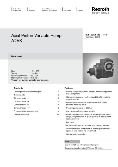
<strong>Axial</strong> <strong>Piston</strong> <strong>Variable</strong> <strong>Pump</strong><br />
<strong>A2VK</strong><br />
Size 12 to 107<br />
Series 1 and 4<br />
Nominal pressure 250 bar<br />
Maximum pressure 315 bar<br />
Version for pumping plastic components<br />
Ordering code for standard program 2<br />
Technical data 3<br />
Dimensions size 12 5<br />
Dimensions size 28 6<br />
Dimensions size 55 7<br />
Dimensions size 107 8<br />
Pressure limiting valve attached 9<br />
General instructions 12<br />
Linear Motion and<br />
Assembly Technologies Pneumatics<br />
Service<br />
Features<br />
– <strong>Variable</strong> axial piston pump for pumping and metering polyurethane<br />
components<br />
– High metering accuracy and reproducibility of the variable<br />
pumped volumes<br />
– Robust manual adjustment via handwheel with integral<br />
precision measuring scale<br />
– Operating pressure up to 250 bar<br />
– Low pulsation of the pumped medium<br />
– <strong>Pump</strong> components are compatible with the pumped media<br />
(polyol, isocyanate) due to special pairings of materials and<br />
sealing elements<br />
– Low-noise<br />
– Excellent volumetric efficiency for high metering accuracy<br />
– Double shaft seals with buffer fluid ports to guarantee safe<br />
operation (and protect the environment)<br />
– With corrosion protection<br />
Note<br />
RE 94001/06.10 1/12<br />
Replaces: 07.04<br />
Size 12 and 28 are in the phase-out program.<br />
Replacement product is the A7VK, see RE 94010.
2/12 <strong>Bosch</strong> <strong>Rexroth</strong> AG <strong>A2VK</strong> Series 1 and 4 RE 94001/06.10<br />
Ordering code for standard program<br />
<strong>Axial</strong> piston unit<br />
<strong>Variable</strong> pump <strong>A2VK</strong><br />
Size<br />
Displacement Vg max in cm 3 12 28 55 107<br />
Control device<br />
s s<br />
Manual adjustment MA<br />
Operating mode<br />
Open circuit O<br />
Closed circuit G<br />
Direction of rotation<br />
Looking onto drive shaft clockwise R<br />
Series<br />
Model<br />
<strong>A2VK</strong> MA G P E – SO2<br />
anti-clockwise L<br />
Size 28-107 1<br />
Size 12 4<br />
Enclosed pump G<br />
Valve attachment<br />
Without valve attached 0<br />
Pressure limiting valve attached 1<br />
Drive shaft<br />
Cylindrical with key P<br />
Swivel angle<br />
One-sided E<br />
Handwheel assembly version<br />
Looking onto drive shaft left side 1<br />
Corrosion-protected version<br />
= Available s = Phase-out program<br />
right side 2<br />
SO2
RE 94001/06.10 <strong>A2VK</strong> Series 1 and 4 <strong>Bosch</strong> <strong>Rexroth</strong> AG 3/12<br />
Technical data<br />
Fluid<br />
The pump pumps and meters fluids for manufacturing polyurethane<br />
(polyol and isocyanate components).<br />
Operating viscosity range<br />
The following limit conditions apply:<br />
ν ________________________________________ 1 mm min 2 /s,<br />
ν _____________________________________ 2000 mm max 2 /s<br />
Please contact us if higher values are required.<br />
Operating temperature range<br />
Optimum operating temperature range t ___________10-50°C<br />
Maximum operating temperature tmax ________________ 80°C<br />
The permitted working temperature depends on the lubricity of<br />
the fluid. The maximum fluid temperature must not be exceeded<br />
even locally (e.g. no more than 5K over the leakage fluid temperature).<br />
Filtering the fluid<br />
The filter should be arranged so that only filtered fluid enters<br />
the pump. The finer the filter, the longer the service life of your<br />
axial piston pump.<br />
We recommend a filter grade ηabs. ≤ _______________125 µm<br />
Operating pressure range<br />
Input<br />
Open circuit:<br />
Max. filling pressure at the port S pmax abs. ___________10 bar<br />
Min. filling pressure at the port S pmin abs. _____________1 bar<br />
The pump must always be filled completely.<br />
Closed circuit:<br />
Leakage fluid pressure pmax abs. ____________________10 bar<br />
Max. intermittent cumulative pressure A + B pmax ___ 250 bar<br />
Output<br />
Maximum pressure at port A or B<br />
(pressure data according to DIN 24312)<br />
Nominal pressure pN ___________________________ 250 bar<br />
Maximum pressure pmax _________________________315 bar<br />
Leakage fluid<br />
Max. leakage fluid pressure pL max __________________10 bar<br />
In the closed circuit, pump ports A and B are separated from<br />
the housing space. The leakage fluid must be removed via port<br />
T1 or T2 using a separate line.<br />
In the open circuit, the suction port S is connected to the<br />
housing space. There is no need for a line for the leakage fluid.<br />
Ports T1 and T2 are plugged. The filling pressure at port S acts<br />
on the shaft sealing ring via the housing space.<br />
The service life of the shaft sealing ring decreases as the<br />
pressure of the leakage fluid or the filling pressure at port S<br />
increases.<br />
Through put flow<br />
Swivel<br />
direction<br />
clockwise<br />
anti-<br />
clockwise<br />
Direction of rotation<br />
“clockwise”<br />
open<br />
circuit<br />
S to B<br />
A plugged<br />
S to A<br />
B plugged<br />
Installation position<br />
closed<br />
circuit<br />
A to B<br />
B to A<br />
Direction of rotation<br />
“anti-clockwise”<br />
open<br />
circuit<br />
S to A<br />
B plugged<br />
S to B<br />
A plugged<br />
closed<br />
circuit<br />
B to A<br />
A to B<br />
Any. The pump must be completely filled with fluid. If installed<br />
with the shaft pointing upwards, the top leakage fluid port must<br />
be connected to the housing for both types of circuit to ensure<br />
that the housing is vented in the vicinity of the bearing.<br />
Preferred installation position: drive shaft horizontal<br />
The adjustment display in the handwheel can only be<br />
guaranteed to work if the adjusting spindle is installed<br />
-30° to +30° from the horizontal.
4/12 <strong>Bosch</strong> <strong>Rexroth</strong> AG <strong>A2VK</strong> Series 1 and 4 RE 94001/06.10<br />
Technical data<br />
Table of values<br />
Size 12 28 55 107<br />
Displacement Vg max cm 3 11.6 28.1 54.8 107<br />
Flow 1 )<br />
at speed n<br />
Power<br />
at ∆p = 250 bar<br />
and speed n<br />
1 ) Includes 3% loss of displacement<br />
Control unit MA<br />
Turning the handwheel turns a self-locking threaded spindle<br />
which steplessly adjusts the pump’s swivel section, and thus<br />
the volumetric flow in the range from Vg 0 to Vg max.<br />
��<br />
��<br />
��<br />
�<br />
�<br />
�<br />
��<br />
��<br />
qv max n = 735 rpm l/min 8.3 20 39.1 76.3<br />
��<br />
��<br />
�<br />
n = 970 rpm l/min 10.9 26.4 51.6 100.7<br />
n = 1450 rpm l/min 16.3 39.5 77.1 150.5<br />
n = 1800 rpm l/min 20.3 49.1 95.7 186.8<br />
Pmax n = 735 rpm kW 3.4 8.3 16.3 31.8<br />
n = 970 rpm kW 4.5 11 21.5 41.9<br />
n = 1450 rpm kW 6.8 16.5 32.1 62.7<br />
n = 1800 rpm kW 8.4 20.4 39.9 77.8<br />
�� ������<br />
Control unit MA 12 28 55 107<br />
Handwheel turns from Vg 0 to Vg max Us 10.6 12.7 16 13.4<br />
Max. handwheel adjustment force Fmax N 70 70 80 120<br />
Mass, approx. (pump with control unit) kg 19 36 64 117<br />
Circuit diagram<br />
closed circuit<br />
Characteristic<br />
��<br />
��<br />
�<br />
� ���<br />
open circuit<br />
��<br />
�<br />
� �����<br />
�<br />
��<br />
��<br />
��<br />
��<br />
�
RE 94001/06.10 <strong>A2VK</strong> Series 1 and 4 <strong>Bosch</strong> <strong>Rexroth</strong> AG 5/12<br />
Dimensions size 12<br />
��<br />
���� ����<br />
�����<br />
��<br />
��<br />
��� �� ��<br />
������������ �� ���<br />
��<br />
���<br />
���<br />
��<br />
��<br />
��<br />
��<br />
( ... ) 1) = open circuit<br />
��<br />
��<br />
��<br />
���������� ��<br />
�� �<br />
��<br />
1 , 2 = handwheel assembly versions<br />
Ports<br />
M6x1; 10 deep<br />
(DIN 13)<br />
�<br />
��<br />
�<br />
�� ��<br />
�����<br />
��<br />
��<br />
����<br />
�<br />
Tightening<br />
torque, max.<br />
A, B Service line ports M22x1.5 4 ) 210 Nm<br />
S Suction port 2 ) G1 1/4 5 ) 720 Nm<br />
T1, T2 Leakage port 3 ) M12x1.5 4 ) 50 Nm<br />
R Air bleed 3 ) M12x1.5 4 ) 50 Nm<br />
U1-U4 Ports for buffer fluid M10x1; 8 deep 4 ) 30 Nm<br />
2 ) plugged in the closed circuit<br />
3 ) plugged<br />
4 ) DIN 3852<br />
5 ) DIN ISO 228<br />
6 ) centering hole to DIN 332<br />
���<br />
��<br />
1<br />
��<br />
2<br />
M8x1.25; 12 deep<br />
(DIN 13)<br />
View X<br />
closed<br />
circuit<br />
View X<br />
open<br />
circuit<br />
Before finalizing your design, request a binding<br />
installation drawing. Dimensions in mm.<br />
���<br />
�<br />
����<br />
���<br />
���<br />
Drive shaft<br />
P Cylinder shaft with key<br />
DIN 6885 – A6x6x25.5<br />
����� �����<br />
�<br />
�<br />
��<br />
��<br />
��<br />
�� ��<br />
�����
6/12 <strong>Bosch</strong> <strong>Rexroth</strong> AG <strong>A2VK</strong> Series 1 and 4 RE 94001/06.10<br />
Dimensions size 28<br />
��<br />
��<br />
����<br />
������<br />
Ports<br />
� �<br />
� �<br />
��<br />
��<br />
��<br />
��<br />
� �<br />
��������� ��<br />
�� � �<br />
� �<br />
� �� ��<br />
���� ���<br />
���<br />
���<br />
�����<br />
����������� �� �<br />
M8x1.25; 11 deep<br />
(DIN 13)<br />
( ... ) 1) = open circuit<br />
1 , 2 = handwheel assembly versions<br />
�<br />
��<br />
�<br />
� �<br />
���<br />
��<br />
����<br />
�<br />
��<br />
Tightening<br />
torque, max.<br />
A, B Service line ports M27x2 4 ) 330 Nm<br />
S Suction port 2 ) G1 1/2 5 ) 960 Nm<br />
T1, T2 Leakage port 3 ) M16x1.5 4 ) 100 Nm<br />
R Air bleed 3 ) M12x1.5 4 ) 50 Nm<br />
U1-U4 Ports for buffer fluid M10x1; 8 deep 4 ) 30 Nm<br />
2 ) plugged in the closed circuit<br />
3 ) plugged<br />
4 ) DIN 3852<br />
5 ) DIN ISO 228<br />
6 ) centering hole to DIN 332<br />
��� ���<br />
1 ���<br />
2<br />
M10x1.5; 15 deep<br />
(DIN 13)<br />
View X<br />
closed<br />
circuit<br />
View X<br />
open<br />
circuit<br />
��<br />
��<br />
Before finalizing your design, request a binding<br />
installation drawing. Dimensions in mm.<br />
���<br />
�<br />
���<br />
���<br />
Drive shaft<br />
P Cylinder shaft with key<br />
DIN 6885 – AS8x7x40<br />
����<br />
�����<br />
����������� �<br />
��<br />
����<br />
��<br />
���<br />
���<br />
�����
RE 94001/06.10 <strong>A2VK</strong> Series 1 and 4 <strong>Bosch</strong> <strong>Rexroth</strong> AG 7/12<br />
Dimensions size 55<br />
��<br />
��<br />
������ ��<br />
��<br />
��<br />
M10x1.5; 12.5 deep<br />
(DIN 13)<br />
�� ��<br />
�� �� ��<br />
�� ���<br />
���<br />
���<br />
��<br />
��<br />
��<br />
��<br />
��<br />
��<br />
���<br />
��<br />
���<br />
���<br />
1 , 2 = handwheel assembly versions<br />
Ports<br />
�<br />
��<br />
��<br />
�<br />
��<br />
�����<br />
���<br />
����<br />
�<br />
��<br />
Tightening<br />
torque, max.<br />
A, B Service line ports M33x2 3 ) 540 Nm<br />
S Suction port 1 ) G2 4 ) 1200 Nm<br />
T1, T2 Leakage port 2 ) M18x1.5 3 ) 140 Nm<br />
R Air bleed 2 ) M12x1.5 3 ) 50 Nm<br />
U1-U4 Ports for buffer fluid M10x1; 8 deep 3 ) 30 Nm<br />
1 ) plugged in the closed circuit<br />
2 ) plugged<br />
3 ) DIN 3852<br />
4 ) DIN ISO 228<br />
5 ) centering hole to DIN 332<br />
���<br />
���<br />
1 ���<br />
2<br />
M16x2;<br />
24 deep<br />
(DIN 13)<br />
View X<br />
closed<br />
circuit<br />
View X<br />
open<br />
circuit<br />
���<br />
���<br />
���<br />
�<br />
Before finalizing your design, request a binding<br />
installation drawing. Dimensions in mm.<br />
���<br />
����<br />
�����<br />
���<br />
Drive shaft<br />
P Cylinder shaft with key<br />
DIN 6885 – AS8x7x43<br />
��������� ��<br />
���<br />
��<br />
��<br />
���<br />
�����<br />
�����<br />
�����
8/12 <strong>Bosch</strong> <strong>Rexroth</strong> AG <strong>A2VK</strong> Series 1 and 4 RE 94001/06.10<br />
Dimensions size 107<br />
120<br />
Ports<br />
78<br />
78<br />
ø160h9<br />
U1<br />
U2<br />
60<br />
74<br />
88<br />
B<br />
30<br />
A<br />
12 90<br />
92 198<br />
238<br />
M12x1.75; 15 deep<br />
(DIN 13)<br />
T1<br />
30<br />
60<br />
584<br />
1 , 2 = handwheel assembly versions<br />
T2<br />
388<br />
412<br />
R<br />
246<br />
155<br />
U3<br />
45<br />
45<br />
ø200<br />
X<br />
U4<br />
8<br />
ø20<br />
M10x1<br />
49<br />
Tightening<br />
torque, max.<br />
A, B Service line ports M42x2 3 ) 720 Nm<br />
S Suction port 1 ) G2 1/2 4 ) 2000 Nm<br />
T1, T2 Leakage port 2 ) M18x1.5 3 ) 140 Nm<br />
R Air bleed 2 ) M12x1.5 3 ) 50 Nm<br />
U1-U4 Ports for buffer fluid M10x1; 8 deep 3 ) 30 Nm<br />
1 ) plugged in the closed circuit<br />
2 ) plugged<br />
3 ) DIN 3852<br />
4 ) DIN ISO 228<br />
5 ) centering hole to DIN 332<br />
View Y<br />
Scale 02:01<br />
308<br />
1 Y<br />
143.5<br />
U3<br />
138.5<br />
2<br />
Y<br />
M16x2; 24 deep<br />
(DIN 13)<br />
View X<br />
closed<br />
circuit<br />
View X<br />
open<br />
circuit<br />
180<br />
180<br />
U4<br />
Before finalizing your design, request a binding<br />
installation drawing. Dimensions in mm.<br />
200<br />
S<br />
236<br />
Drive shaft<br />
P Cylinder shaft with key<br />
DIN 6885 – AS12x8x63<br />
����<br />
�����<br />
����������� ���<br />
��<br />
��<br />
160<br />
150<br />
160<br />
�����
RE 94001/06.10 <strong>A2VK</strong> Series 1 and 4 <strong>Bosch</strong> <strong>Rexroth</strong> AG 9/12<br />
Pressure limiting valve attached<br />
C B1<br />
E<br />
Size C D E F G Service line<br />
port B1 1 )<br />
Tightening<br />
torque, max.<br />
Return<br />
port T3 1 )<br />
D<br />
T3<br />
F<br />
G<br />
Tightening<br />
torque, max.<br />
12 25 109 32 108 131 M22x1.5; 14 deep 210 Nm M18x1.5; 12 deep 140 Nm<br />
28 26.5 121 40 131 156 M27x2; 16 deep 330 Nm M22x1.5; 14 deep 210 Nm<br />
55 31.5 133.5 46 160.5 188.5 M33x2; 18 deep 540 Nm M27x2; 16 deep 330 Nm<br />
107 38.5 174 58 192.5 225 M42x2; 20 deep 720 Nm M33x2; 20 deep 540 Nm<br />
1 ) DIN 3852<br />
Before finalizing your design, request a binding<br />
installation drawing. Dimensions in mm.
10/12 <strong>Bosch</strong> <strong>Rexroth</strong> AG <strong>A2VK</strong> Series 1 and 4 RE 94001/06.10<br />
Notes
RE 94001/06.10 <strong>A2VK</strong> Series 1 and 4 <strong>Bosch</strong> <strong>Rexroth</strong> AG 11/12<br />
Notes
12/12 <strong>Bosch</strong> <strong>Rexroth</strong> AG <strong>A2VK</strong> Series 1 and 4 RE 94001/06.10<br />
General instructions<br />
– The pump <strong>A2VK</strong> is designed for use in an open or closed circuit.<br />
– Configuration, assembly, commissioning of the pump must be performed by trained and qualified personnel.<br />
– The operating and function ports are designed exclusively for connecting fluid lines.<br />
– Tightening torques: The tightening torques specified in this data sheet are maximum values and may not be<br />
ex ceeded (maximum value for screw thread). Manufacturer specifications for the max.<br />
permissible tightening torques of the used fittings must be observed!<br />
For DIN 13 fastening screws we recommend checking the tightening torque individually<br />
according to VDI 2230 Edition 2003.<br />
– The housing temperature rises during and shortly after operation. Take suitable safety precautions (e.g. wear protective clothing).<br />
– Observe the specified data and instructions.<br />
– During maintenance and disposal, please note that the fluids used are potentially harmful to the health. The instructions issued<br />
by the fluid manufacturer must be followed.<br />
<strong>Bosch</strong> <strong>Rexroth</strong> AG<br />
Hydraulics<br />
<strong>Axial</strong> <strong>Piston</strong> Units<br />
Glockeraustrasse 2<br />
89275 Elchingen, Germany<br />
Telephone +49 (0) 73 08 82-0<br />
Fac +49 (0) 73 08 72 74<br />
info.brm-ak@boschrexroth.de<br />
www.boschrexroth.com/axial-piston-pumps<br />
© This document, as well as the data, specifications and other information set<br />
forth in it, are the exclusive property of <strong>Bosch</strong> <strong>Rexroth</strong> AG. It may not be reproduced<br />
or given to third parties without its consent.<br />
The data specified above only serve to describe the product. No statements<br />
concerning a certain condition or suitability for a certain application can be derived<br />
from our information. The information given does not release the user from<br />
the obligation of own judgment and verification. It must be remembered that our<br />
products are subject to a natural process of wear and aging.<br />
Subject to change.