Section 13 - Technical Data - Bosch Rexroth
Section 13 - Technical Data - Bosch Rexroth
Section 13 - Technical Data - Bosch Rexroth

You also want an ePaper? Increase the reach of your titles
YUMPU automatically turns print PDFs into web optimized ePapers that Google loves.
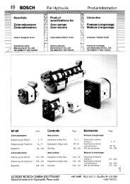
3 842 540 380 (2010.11) TS 5 2.0<br />
<strong>Technical</strong> data<br />
<strong>Technical</strong> data<br />
<strong>Bosch</strong> <strong>Rexroth</strong> AG <strong>13</strong>–1<br />
System specifications F2 <strong>13</strong>-2<br />
Motor data F2 <strong>13</strong>-6<br />
Ordering parameters for SEW motors F2 <strong>13</strong>-10<br />
Conversion table for metric/imperial dimensions F2 <strong>13</strong>-11<br />
Dimensioned drawings F2 <strong>13</strong>-12<br />
1<br />
2<br />
3<br />
4<br />
5<br />
6<br />
7<br />
8<br />
9<br />
10<br />
11<br />
12<br />
<strong>13</strong><br />
14<br />
15<br />
16
<strong>13</strong>–10 <strong>Bosch</strong> <strong>Rexroth</strong> AG<br />
<strong>Technical</strong> data<br />
Ordering parameters for SEW motors<br />
The following ordering information is<br />
required if using gear motors from<br />
SEW-Eurodrive GmbH & Co, Bruchsal:<br />
— Motor type<br />
— Ratio<br />
— Motor mounting, mounting orientation<br />
— Drive output position<br />
— Terminal box position<br />
— Cable entry (Fig. 3)<br />
— Motor voltage/frequency *)<br />
— Thermal class *)<br />
— Motor protection class * )<br />
* ) www.seweurodrive.com<br />
SEW motors motor data<br />
Z<br />
00<strong>13</strong>4833<br />
A<br />
B<br />
TS 5 2.0 3 842 540 380 (2010.11)<br />
Fig. 1 Fig. 2 Fig. 3<br />
400 V/50 Hz 400 V/60 Hz<br />
vN v 1)<br />
i n<strong>13</strong>) n24) MN P5) Type v 1)<br />
i n<strong>13</strong>) n24) MN P5) Type<br />
(m/min) (m/min) (rpm) (rpm) (Nm) (W) SAF37... (m/min) (rpm) (rpm) (Nm) (W) SAF37...<br />
2 2.07 122.94 <strong>13</strong>20 11 91 180 DR63M4 2.07 144.4 1620 11 92 180 DR63M4<br />
4 4.14 55.93 <strong>13</strong>00 22 81 250 DR63L4 4.14 71.44 1600 22 84 250 DR63L4<br />
6 6.03 43.68 <strong>13</strong>80 32 81 370 DRS71S4 6.03 53.83 1700 32 80 370 DRS71S4<br />
9 9.04 28.76 <strong>13</strong>80 48 75 370 DRS71S4 9.04 35.1 1700 48 75 370 DRS71S4<br />
12 11.49 22.5 <strong>13</strong>80 61 73 550 DRS71M4 11.12 28.76 1690 59 75 550 DRS71M4<br />
15 14.32 18.34 <strong>13</strong>80 76 52 550 DRS71M4 14.<strong>13</strong> 22.5 1690 75 73 550 DRS71M4<br />
18 19.41 <strong>13</strong>.39 <strong>13</strong>80 103 49 550 DRS71M4 17.53 18.24 1690 93 52 550 DRS71M4<br />
2 to 7 2)<br />
1.5-7,53 35.1 280-1400 8.0-40 78 370 DRS71S4MM03 1.5-7,53 35.1 280-1400 8.0-40 78 370 DRS71S4MM03<br />
7 to 18 2) 3.95-19,79 <strong>13</strong>.39 280-1400 21-105 49 550 DRS71M4MM05 3.95-19,79 <strong>13</strong>.39 280-1400 21-105 49 550 DRS71M4MM05<br />
1) Transport speeds at other voltages/<br />
frequencies on request.<br />
2) Electronically controlled by a frequency<br />
converter (FC).<br />
3) n1 = motor speed<br />
4) n2 = gear output speed<br />
5) Motor output<br />
Motor mounting orientation, terminal box, cable entry (Fig. 3)<br />
Motor mounting Mounting orientation Drive output Terminal box<br />
MA (Fig. 2) (Fig. 1) (Fig. 1)<br />
R M2 B 0°<br />
L M2 A 180°<br />
AS 5/XH, AS 5/H technical data:<br />
Max. torque limit: 45 Nm (toothed belt) limit<br />
Toothed belt drive gear ratio: 1:1<br />
Flange ø: 120 mm<br />
Drive shaft: SW27 on shaft ø 20<br />
Conveyor roller ø: 60 mm<br />
M2<br />
Z<br />
1<br />
2<br />
X<br />
3
3 842 540 380 (2010.11) TS 5 2.0<br />
<strong>Technical</strong> data<br />
Conversion table for metric/imperial dimensions<br />
Measurement multiply by to get:<br />
<strong>Bosch</strong> <strong>Rexroth</strong> AG <strong>13</strong>–11<br />
Linear millimeters (mm) 0.03937 inches<br />
inches 25.4 millimeters (mm)<br />
kilometers (km) 0.6214 miles<br />
miles 1.6093 kilometers (km)<br />
Area millimeters2 (mm2 ) 0.00155 inches2 inches2 645.16 millimeters2 (mm2 )<br />
Volume centimeters3 (cm3) 0.06102 inches2 inches3 16,387 centimeters3 (cm3 1 cm<br />
)<br />
3 = 1 milliliter (ml)<br />
1000 ml = 1 liter<br />
Acceleration meter/second2 (m/s2 ) 39.37 inch/second2 inch/second2 0.0254 meter/second2 (m/s2 )<br />
Velocity meter/second 3,281 feet/second<br />
feet/second 0.3048 meter/second<br />
Mass kilogram (kg) 2.2046 pounds<br />
pounds 0.4536 kilogram (kg)<br />
Force kilograms-f (kgf) 9,807 Newtons (N)<br />
Newtons (N) 0.10194 kilograms-f (kgf)<br />
pounds-f 4,448 Newtons (N)<br />
Pressure Newtons 0.2248 pounds-f<br />
bar 14.5 PSI<br />
PSI 00.069 bar<br />
Torque Newton meters (Nm) 8,851 pound-inches<br />
pound-inches 0.11298 Newton meters (Nm)<br />
Moment of inertia centimeters4 (cm4 ) 0.02403 inches4 inches4 41,623 centimeters4 (cm4 )<br />
Power kilowatts (kW) 1.34 horsepower (HP)<br />
horsepower (HP) 00.746 kilowatts (kW)<br />
Energy Joules (J) 0.7376 feet/pounds (ft/lbs)<br />
feet/pounds (ft/lbs) 1.3558 Joules (J)<br />
Metric tap/drill specifications<br />
Tap Drill size<br />
M4 × 0.7 2.5 mm<br />
M5 × 0.8 2.5 mm<br />
M6 × 1 2.5 mm<br />
M8 × 1.25 2.5 mm<br />
M12 × 1.75 14.0 mm<br />
M16 × 2 14.0 mm<br />
Temperature<br />
Degrees Celsius<br />
5 × (degrees Fahrenheit – 32)<br />
9<br />
Degrees Fahrenheit<br />
9 × (degrees Celsius) + 32<br />
5<br />
1<br />
2<br />
3<br />
4<br />
5<br />
6<br />
7<br />
8<br />
9<br />
10<br />
11<br />
12<br />
<strong>13</strong><br />
14<br />
15<br />
16
<strong>13</strong>–12 <strong>Bosch</strong> <strong>Rexroth</strong> AG<br />
<strong>Technical</strong> data<br />
Dimensioned drawings<br />
WT 5 workpiece pallet<br />
00<strong>13</strong>2883<br />
b = b WT<br />
l = l WT 37<br />
= =<br />
A Damping element<br />
B Bracket for ID ... data tag<br />
C Stop-gate recess<br />
D Bracket for positioning bushing<br />
E Guide rollers<br />
F2 2-4<br />
l 1<br />
= =<br />
b 1<br />
C<br />
E<br />
TS 5 2.0 3 842 540 380 (2010.11)<br />
b WT l WT m WT F b 1 l 1 No.<br />
(mm) (mm) (kg) (kg) (mm) (mm)<br />
455 455 6.4 150 195 195 3 842 545 254<br />
455 650 8.9 215 195 325 3 842 545 255<br />
650 650 <strong>13</strong>.5 215 325 325 3 842 545 256<br />
650 845 17.2 300 325 520 3 842 545 257<br />
845 845 23.2 300 520 520 3 842 545 258<br />
845 1040 27.2 300 520 715 3 842 545 259<br />
m WT = weight of the workpiece pallet<br />
F = permissible workpiece pallet loading weight on the conveyor medium<br />
D<br />
B<br />
A
3 842 540 380 (2010.11) TS 5 2.0<br />
<strong>Technical</strong> data<br />
WT 5: carrying plates, standard sizes<br />
00<strong>13</strong>2884<br />
F2 2-8<br />
b = b Pl – 4<br />
l = l Pl – 4<br />
= =<br />
l 1<br />
= =<br />
b 1<br />
<strong>Bosch</strong> <strong>Rexroth</strong> AG <strong>13</strong>–<strong>13</strong><br />
b WT l WT d PL * m PL No.<br />
(mm) (mm) (mm) (mm) (kg)<br />
455 455 12.7 0.6 6.9 3 842 545 081<br />
455 650 12.7 0.8 9.9 3 842 545 084<br />
650 650 12.7 0.8 14.3 3 842 545 087<br />
650 845 12.7 1.0 18.6 3 842 545 090<br />
845 845 12.7 1.0 24.2 3 842 545 093<br />
845 1040 12.7 1.2 29.8 3 842 545 096<br />
b WT l WT d PL * m PL No.<br />
(mm) (mm) (mm) (mm) (kg)<br />
455 455 19.05 0.6 10.4 3 842 545 266<br />
455 650 19.05 0.8 14.9 3 842 545 267<br />
650 650 19.05 0.8 21.4 3 842 545 268<br />
650 845 19.05 1.0 27.9 3 842 545 269<br />
845 845 19.05 1.0 36.3 3 842 545 270<br />
845 1040 19.05 1.2 44.7 3 842 545 271<br />
d PL = plate thickness<br />
* = evenness<br />
m PL = plate weight<br />
d PI<br />
11<br />
22,5<br />
11<br />
23,5 H7<br />
4<br />
1<br />
2<br />
3<br />
4<br />
5<br />
6<br />
7<br />
8<br />
9<br />
10<br />
11<br />
12<br />
<strong>13</strong><br />
14<br />
15<br />
16
<strong>13</strong>–14 <strong>Bosch</strong> <strong>Rexroth</strong> AG<br />
<strong>Technical</strong> data<br />
Dimensioned drawings<br />
WT 5: carrying plate, variable dimensions<br />
00<strong>13</strong>2885<br />
b WT<br />
b Pl<br />
WT x l<br />
l WT<br />
�� 2-9<br />
b PL<br />
l Pl<br />
= =<br />
l 1<br />
l PL<br />
d PL<br />
* Nr.<br />
(mm) (mm) (mm) (mm) (mm)<br />
455 x 455 451 ≤ b PL ≤ 650 451 ≤ l PL ≤ 650 12,7 0,6 3 842 998 562<br />
455 x 650 451 ≤ b PL ≤ 650 646 ≤ l PL ≤ 845 12,7 0,8 3 842 998 564<br />
650 x 650 646 ≤ b PL ≤ 845 646 ≤ l PL ≤ 845 12,7 0,8 3 842 998 566<br />
650 x 845 646 ≤ b PL ≤ 845 841 ≤ l PL ≤ 1040 12,7 1,0 3 842 998 568<br />
845 x 845 841 ≤ b PL ≤ 1040 841 ≤ l PL ≤ 1040 12,7 1,0 3 842 998 570<br />
845 x 1040 841 ≤ b PL ≤ 1040 1036 ≤ l PL ≤ 1250 12,7 1,2 3 842 998 572<br />
b WT<br />
WT x l<br />
l WT<br />
bPL PL<br />
lPL PL<br />
dPL PL<br />
* Nr.<br />
(mm) (mm) (mm) (mm) (mm)<br />
455 x 455 451 ≤ b PL ≤ 650 451 ≤ l PL ≤ 650 19,05 0,6 3 842 998 563<br />
455 x 650 451 ≤ b PL ≤ 650 646 ≤ l PL ≤ 845 19,05 0,8 3 842 998 565<br />
650 x 650 646 ≤ b PL ≤ 845 646 ≤ l PL ≤ 845 19,05 0,8 3 842 998 567<br />
650 x 845 646 ≤ b PL ≤ 845 841 ≤ l PL ≤ 1040 19,05 1,0 3 842 998 569<br />
845 x 845 841 ≤ b PL ≤ 1040 841 ≤ l PL ≤ 1040 19,05 1,0 3 842 998 571<br />
845 x 1040 841 ≤ b PL ≤ 1040 1036 ≤ l PL ≤ 1250 19,05 1,2 3 842 998 573<br />
d PL = plate thickness<br />
* = evenness<br />
= =<br />
b 1<br />
d PI<br />
TS 5 2.0 3 842 540 380 (2010.11)<br />
11<br />
22,5<br />
11<br />
23,5 H7<br />
Formula for calculating the weight of a<br />
carrying plate:<br />
m PL (kg) = b PL (mm) x l PL (mm) x d PL (mm)<br />
x 0,0000027 (kg/mm 3 )<br />
4
3 842 540 380 (2010.11) TS 5 2.0<br />
<strong>Technical</strong> data<br />
AS 5/H, AS 5/XH drive modules<br />
00<strong>13</strong>2886<br />
AS 5/XH<br />
AS 5/H<br />
F2 3-4<br />
390<br />
390<br />
160<br />
229 289<br />
318 199<br />
FU<br />
98<br />
98<br />
b = b WT<br />
289<br />
199<br />
b+3<br />
b–10<br />
b+80 50<br />
b+3<br />
b–10<br />
60 33,5<br />
33,5<br />
<strong>Bosch</strong> <strong>Rexroth</strong> AG <strong>13</strong>–15<br />
246<br />
b+80 50<br />
246<br />
376<br />
376<br />
228<br />
318<br />
230<br />
320<br />
AS 5/XH: 3 842 998 532<br />
AS 5/H: 3 842 998 533<br />
1<br />
2<br />
3<br />
4<br />
5<br />
6<br />
7<br />
8<br />
9<br />
10<br />
11<br />
12<br />
<strong>13</strong><br />
14<br />
15<br />
16
<strong>13</strong>–16 <strong>Bosch</strong> <strong>Rexroth</strong> AG<br />
<strong>Technical</strong> data<br />
Dimensioned drawings<br />
AS 5/H-FR, AS 5/XH-FR drive modules<br />
00<strong>13</strong>2887<br />
AS 5/XH-FR<br />
AS 5/H-FR<br />
F2 3-5<br />
390<br />
390<br />
160<br />
229 289<br />
318 199<br />
FU<br />
98<br />
98<br />
b = b WT<br />
289<br />
199<br />
b+3<br />
b–10<br />
b+80 50<br />
b+3<br />
b–10<br />
TS 5 2.0 3 842 540 380 (2010.11)<br />
33,5 33,5<br />
60<br />
246<br />
b+80 50<br />
246<br />
376<br />
376<br />
228<br />
318<br />
230<br />
320<br />
AS 5/XH-FR: 3 842 998 534<br />
AS 5/H-FR: 3 842 998 535
3 842 540 380 (2010.11) TS 5 2.0<br />
<strong>Technical</strong> data<br />
AS 5/OC drive module (Open Center)<br />
00<strong>13</strong>7464<br />
AS 5/OC<br />
DD = 1<br />
AS 5/OC<br />
DD = 3<br />
DD = 1<br />
FU<br />
390<br />
390<br />
160<br />
98<br />
DD = 2<br />
1) DD = 2: Join the drive side without the gear motor to a gear-driven section.<br />
F2 3-6<br />
FU<br />
1)<br />
98<br />
199<br />
199<br />
50<br />
376<br />
246<br />
DD = 3<br />
FU<br />
b+3<br />
b–190<br />
b+80 50<br />
b+3<br />
b–190<br />
60 33,5<br />
33,5<br />
<strong>Bosch</strong> <strong>Rexroth</strong> AG <strong>13</strong>–17<br />
246<br />
b+80 50<br />
246<br />
376<br />
376<br />
318<br />
318<br />
320<br />
320<br />
b = b WT<br />
AS 5/OC: 3 842 998 575<br />
1<br />
2<br />
3<br />
4<br />
5<br />
6<br />
7<br />
8<br />
9<br />
10<br />
11<br />
12<br />
<strong>13</strong><br />
14<br />
15<br />
16
<strong>13</strong>–18 <strong>Bosch</strong> <strong>Rexroth</strong> AG<br />
<strong>Technical</strong> data<br />
Dimensioned drawings<br />
ST 5/XH, ST 5/H conveyor units<br />
00<strong>13</strong>2888<br />
ST 5/XH<br />
ST 5/H<br />
F2 4-3<br />
p 2<br />
p = = = = =<br />
60<br />
l<br />
l<br />
p 2<br />
289<br />
199<br />
98<br />
98<br />
TS 5 2.0 3 842 540 380 (2010.11)<br />
b = b WT<br />
b +3<br />
33,5<br />
b +3<br />
33,5<br />
b-10<br />
b+80 50<br />
ST 5/XH: 3 842 998 521<br />
ST 5/H: 3 842 998 520
3 842 540 380 (2010.11) TS 5 2.0<br />
<strong>Technical</strong> data<br />
ST 5/XH-FR, ST 5/H-FR conveyor units<br />
00<strong>13</strong>2889<br />
ST 5/XH-FR<br />
ST 5/H-FR<br />
F2 4-7<br />
p 2<br />
60<br />
l<br />
l<br />
p = = = = =<br />
p 2<br />
289<br />
199<br />
98<br />
98<br />
b = b WT<br />
<strong>Bosch</strong> <strong>Rexroth</strong> AG <strong>13</strong>–19<br />
b +3<br />
33,5<br />
b +3<br />
33,5<br />
b-10<br />
b+80 50<br />
ST 5/XH-FR: 3 842 998 523<br />
ST 5/H-FR: 3 842 998 522<br />
1<br />
2<br />
3<br />
4<br />
5<br />
6<br />
7<br />
8<br />
9<br />
10<br />
11<br />
12<br />
<strong>13</strong><br />
14<br />
15<br />
16
<strong>13</strong>–2 <strong>Bosch</strong> <strong>Rexroth</strong> AG<br />
<strong>Technical</strong> data<br />
System specifications<br />
Application<br />
The <strong>Rexroth</strong> transfer systems all form<br />
a program of fine-tuned mechanical<br />
components that are used to convey,<br />
separate, and position workpiece pallets.<br />
With these components, you can create<br />
almost any system layout you need.<br />
The systems are primarily used to convey<br />
workpieces (on <strong>Rexroth</strong> workpiece<br />
pallets) to and from manual or automatic<br />
work stations on an assembly line.<br />
Planning<br />
Transfer system planning, setup, initial<br />
start-up and maintenance should only<br />
be done by trained personnel. <strong>Rexroth</strong><br />
offers training courses for this.<br />
Scope of delivery – small parts<br />
The proximity switches, pneumatic<br />
valves, and electrical and pneumatic<br />
installation material that are necessary<br />
for operation are usually not included in<br />
the scope of delivery. These parts are<br />
only preassembled if they guarantee<br />
special functional safety or if installing<br />
them at a later point would require too<br />
much effort.<br />
The notes on the required flow control<br />
valves and check valves in the pneumatic<br />
switching plan (listed in the assembly<br />
and operation instructions) must be<br />
followed.<br />
Notes<br />
Examples<br />
Installation references, pneumatic<br />
switching plans and typical function<br />
processes are described in the catalogs<br />
and assembly instructions. These must<br />
be followed when setting up and initially<br />
operating the system.<br />
CE identification, responsibility<br />
Components that fall under the EC<br />
Machinery Directive are delivered with<br />
the corresponding manufacturer’s<br />
declaration. Overall responsibility for<br />
system safety (declaration of conformity,<br />
CE identification) lies with the system<br />
builder. The references in the assembly<br />
instructions and in the Instructions for<br />
Employees on Safety – 3 842 527 147<br />
must be followed.<br />
Ambient conditions<br />
Environmental conditions - climatic<br />
The transfer systems have been<br />
designed for stationary use in a location<br />
that is protected from the elements.<br />
Operating temperature<br />
+5 to +40°C<br />
–5 to +60°C with 20%<br />
reduced load<br />
Storage temperature<br />
–25°C to +70°C<br />
Relative humidity<br />
5 to 85%, non-condensing<br />
Air pressure<br />
> 84 kPa appropriate for a height<br />
< 1400 m above sea level.<br />
Load values are reduced by 15%<br />
when the system is set up at a location<br />
that is over 1400 m above sea level.<br />
TS 5 2.0 3 842 540 380 (2010.11)<br />
Environmental conditions – biological<br />
Avoid molds, fungi, rodents, and other<br />
vermin.<br />
Environmental conditions – physical<br />
Do not install near sandy or dusty<br />
sources.<br />
Do not install in areas that are regularly<br />
jarred by high forces caused by<br />
e.g. presses, heavy machinery, etc.<br />
Environmental conditions – chemical<br />
Do not install near industrial systems<br />
with chemical emissions.<br />
Materials used<br />
The materials used in the components<br />
are primarily:<br />
— Non-rusting steel or steel protected<br />
against corrosion by a special<br />
surface,<br />
— Brass,<br />
— Cast or malleable aluminum alloy,<br />
— Polyurethane, polyamide, some<br />
with additives to improve electrical<br />
and mechanical characteristics and<br />
UHMW polyethylene.<br />
— NBR or Viton for elastic seals.
<strong>13</strong>–20 <strong>Bosch</strong> <strong>Rexroth</strong> AG<br />
<strong>Technical</strong> data<br />
Dimensioned drawings<br />
ST 5/OC conveyor unit (Open Center)<br />
00<strong>13</strong>7466<br />
ST 5/OC<br />
DD = 1<br />
ST 5/OC<br />
DD = 2<br />
p 2<br />
p = = = = = =<br />
60<br />
F2 4-10<br />
l<br />
l<br />
p 2<br />
98<br />
199<br />
199<br />
98<br />
50<br />
TS 5 2.0 3 842 540 380 (2010.11)<br />
b +3<br />
b-190<br />
b+80<br />
b-190<br />
b+80<br />
b = b WT b+3<br />
33,5<br />
33,5<br />
ST 5/OC: 3 842 998 574<br />
50<br />
50
3 842 540 380 (2010.11) TS 5 2.0<br />
<strong>Technical</strong> data<br />
CU 5/H, CU 5/XH curves<br />
00<strong>13</strong>2893<br />
b 1)<br />
l 1<br />
b+3<br />
l 2<br />
50<br />
65<br />
50 b+80<br />
50<br />
65<br />
F2 5-4<br />
2)<br />
lWT b = b WT<br />
l 4<br />
3)<br />
l1 l 3<br />
l = l WT<br />
CU 5/XH<br />
CU 5/H<br />
(mm) (mm) (mm) (mm) (mm) (mm)<br />
455 455; 650 921.5 382.5 650 917.5<br />
650 650; 845 1149 415 780 1145<br />
845 845; 1040 <strong>13</strong>76.5 447 910 <strong>13</strong>72.5<br />
4)<br />
l2 50<br />
b+3<br />
l 3<br />
5)<br />
l3 CU 5/XH: 3 842 998 526<br />
CU 5/H: 3 842 998 525<br />
l 4<br />
<strong>Bosch</strong> <strong>Rexroth</strong> AG <strong>13</strong>–21<br />
289<br />
199<br />
1) b = track width in direction of<br />
transport<br />
2) lWT = workpiece pallet length<br />
(in direction of transport)<br />
3) l1 = length of main section<br />
4) l2 = length of secondary section<br />
5) l3 = length of secondary section to<br />
center of main section<br />
1<br />
2<br />
3<br />
4<br />
5<br />
6<br />
7<br />
8<br />
9<br />
10<br />
11<br />
12<br />
<strong>13</strong><br />
14<br />
15<br />
16
<strong>13</strong>–22 <strong>Bosch</strong> <strong>Rexroth</strong> AG<br />
<strong>Technical</strong> data<br />
Dimensioned drawings<br />
DI 5/H, DI 5/XH diverters<br />
00<strong>13</strong>2894<br />
l 1<br />
b 1)<br />
50 b+80<br />
50<br />
2)<br />
lWT b+3<br />
b = b WT<br />
l 4<br />
3)<br />
l1 l 3<br />
l = l WT<br />
65<br />
l 2<br />
65<br />
b+3<br />
l 2<br />
50 50<br />
65<br />
l 2<br />
b+80<br />
l 3<br />
DI 5/XH<br />
DI 5/H<br />
(mm) (mm) (mm) (mm) (mm) (mm)<br />
455 455; 650 <strong>13</strong>00 382.5 650 917.5<br />
650 650; 845 1560 415 780 1145<br />
845 845; 1040 1820 447 910 <strong>13</strong>72.5<br />
F2 5-6<br />
4)<br />
l2 5)<br />
l3 DI 5/XH: 3 842 998 529<br />
DI 5/H: 3 842 998 528<br />
l 4<br />
TS 5 2.0 3 842 540 380 (2010.11)<br />
289<br />
8<br />
199<br />
98<br />
1) b = track width in direction of<br />
transport<br />
2) lWT = workpiece pallet length<br />
(in direction of transport)<br />
3) l1 = length of main section<br />
4) l2 = length of secondary section<br />
5) l3 = length of secondary section to<br />
center of main section
3 842 540 380 (2010.11) TS 5 2.0<br />
<strong>Technical</strong> data<br />
JU 5/H, JU 5/XH junctions<br />
00<strong>13</strong>2895<br />
b 1)<br />
l 1<br />
50 b+80<br />
50<br />
F2 5-8<br />
2)<br />
lWT b+3<br />
b = b WT<br />
l 4<br />
3)<br />
l1 l 3<br />
l = l WT<br />
JU 5/XH<br />
JU 5/H<br />
(mm) (mm) (mm) (mm) (mm) (mm)<br />
455 455; 650 <strong>13</strong>00 382.5 650 917.5<br />
650 650; 845 1560 415 780 1145<br />
845 845; 1040 1820 447 910 <strong>13</strong>72.5<br />
65<br />
l 2<br />
4)<br />
l2 65<br />
b+3<br />
l 2<br />
50<br />
50<br />
65<br />
l 2<br />
b+80<br />
l 3<br />
5)<br />
l3 JU 5/XH: 3 842 998 531<br />
JU 5/H: 3 842 998 530<br />
l 4<br />
<strong>Bosch</strong> <strong>Rexroth</strong> AG <strong>13</strong>–23<br />
98 199<br />
8 289<br />
1) b = track width in direction of<br />
transport<br />
2) lWT = workpiece pallet length<br />
(in direction of transport)<br />
3) l1 = length of main section<br />
4) l2 = length of secondary section<br />
5) l3 = length of secondary section to<br />
center of main section<br />
1<br />
2<br />
3<br />
4<br />
5<br />
6<br />
7<br />
8<br />
9<br />
10<br />
11<br />
12<br />
<strong>13</strong><br />
14<br />
15<br />
16
<strong>13</strong>–24 <strong>Bosch</strong> <strong>Rexroth</strong> AG<br />
<strong>Technical</strong> data<br />
Dimensioned drawings<br />
HQ 5 lift transverse unit<br />
b+35<br />
00<strong>13</strong>4848<br />
b HQ<br />
F2 6-4<br />
l HQ<br />
b Q<br />
b L b Q b HQ l HQ l 2<br />
(mm) (mm) (mm) (mm) (mm)<br />
455 455 454 609 382.5<br />
650 650 649 609 415<br />
845 845 844 854 447<br />
650 845 649 854 415<br />
845 1040 844 984 447<br />
l 2<br />
TS 5 2.0 3 842 540 380 (2010.11)<br />
l = lWT bQ = lWT DA 5/200:<br />
DA 5/1000:<br />
146 10<br />
b = bWT bL = bWT HQ 5: 3 842 998 514<br />
152<br />
176<br />
Assembly kit for installing the HQ 5 in the<br />
ST 5/H: no. 3 842 996 226
3 842 540 380 (2010.11) TS 5 2.0<br />
<strong>Technical</strong> data<br />
PE 5 positioning unit<br />
b+35<br />
00<strong>13</strong>2892<br />
b PE<br />
F2 8-3<br />
l PE<br />
b WT l WT b PE l PE<br />
(mm) (mm) (mm) (mm)<br />
455 455; 650 441 605<br />
650 650 636 605<br />
650 845 636 785<br />
845 845 831 785<br />
845 1040 831 980<br />
<strong>Bosch</strong> <strong>Rexroth</strong> AG <strong>13</strong>–25<br />
l = l WT<br />
146 10 4<br />
b = b WT<br />
PE 5: 3 842 998 512<br />
Assembly kit for installing the PE 5 in the<br />
ST 5/H: no. 3 842 996 185<br />
1<br />
2<br />
3<br />
4<br />
5<br />
6<br />
7<br />
8<br />
9<br />
10<br />
11<br />
12<br />
<strong>13</strong><br />
14<br />
15<br />
16
<strong>13</strong>–26 <strong>Bosch</strong> <strong>Rexroth</strong> AG<br />
<strong>Technical</strong> data<br />
Dimensioned drawings<br />
VE 5/200; VE 5/OC-200 stop gates<br />
00<strong>13</strong>7470<br />
F2 9-7<br />
C<br />
=<br />
C<br />
35<br />
= =<br />
35<br />
b -10<br />
A<br />
b -10<br />
35<br />
A<br />
35<br />
=<br />
B<br />
6<br />
B<br />
b = b WT<br />
VE 5/200: 3 842 998 518<br />
b = b WT<br />
VE 5/OC-200: 3 842 998 577<br />
6<br />
TS 5 2.0 3 842 540 380 (2010.11)<br />
A = stop gates<br />
B = 6 mm pushlock-type compressed air<br />
connection<br />
C = position inquiry VE stop blade up:<br />
yes/no
3 842 540 380 (2010.11) TS 5 2.0<br />
<strong>Technical</strong> data<br />
VE 5/D-300; VE 5/OCD-300 stop gates<br />
00<strong>13</strong>7472<br />
F2 9-8<br />
6<br />
B<br />
35<br />
35<br />
A<br />
D<br />
= C<br />
=<br />
35<br />
b -10<br />
C<br />
= =<br />
b -10<br />
35<br />
A<br />
D<br />
6<br />
B<br />
b = b WT<br />
VE 5/D-300: 3 842 998 517<br />
b = b WT<br />
VE 5/OCD-300: 3 842 998 578<br />
<strong>Bosch</strong> <strong>Rexroth</strong> AG <strong>13</strong>–27<br />
A = stop gates<br />
B = 6 mm pushlock-type compressed air<br />
connection<br />
C = position inquiry VE stop blade:<br />
up/down<br />
D = position inquiry VE stop blade,<br />
damper retracted: yes/no<br />
1<br />
2<br />
3<br />
4<br />
5<br />
6<br />
7<br />
8<br />
9<br />
10<br />
11<br />
12<br />
<strong>13</strong><br />
14<br />
15<br />
16
<strong>13</strong>–28 <strong>Bosch</strong> <strong>Rexroth</strong> AG<br />
<strong>Technical</strong> data<br />
Dimensioned drawings<br />
VE 5/D-1000 stop gates<br />
00<strong>13</strong>2922<br />
F2 9-9<br />
35<br />
C<br />
35<br />
= =<br />
b -10<br />
A<br />
D<br />
6<br />
B<br />
b = b WT<br />
VE 5/D-1000: 3 842 998 516<br />
TS 5 2.0 3 842 540 380 (2010.11)<br />
A = stop gates<br />
B = 6 mm pushlock-type compressed air<br />
connection<br />
C = position inquiry VE stop blade:<br />
up/down<br />
D = position inquiry VE stop blade,<br />
damper retracted: yes/no
3 842 540 380 (2010.11) TS 5 2.0<br />
<strong>Technical</strong> data<br />
VE 5/OCD-1000 stop gates<br />
00<strong>13</strong>7474<br />
F2 9-9<br />
6<br />
B<br />
35<br />
C<br />
= =<br />
b -10<br />
35<br />
D<br />
A<br />
b = b WT<br />
VE 5/OCD-1000: 3 842 998 579<br />
<strong>Bosch</strong> <strong>Rexroth</strong> AG <strong>13</strong>–29<br />
A = stop gates<br />
B = 6 mm pushlock-type compressed air<br />
connection<br />
C = position inquiry VE stop blade:<br />
up/down<br />
D = position inquiry VE stop blade,<br />
damper retracted: yes/no<br />
1<br />
2<br />
3<br />
4<br />
5<br />
6<br />
7<br />
8<br />
9<br />
10<br />
11<br />
12<br />
<strong>13</strong><br />
14<br />
15<br />
16
3 842 540 380 (2010.11) TS 5 2.0<br />
<strong>Technical</strong> data<br />
Media resistance<br />
Resistant to many common media used<br />
in production such as water, mineral oil,<br />
grease, and detergents. Contact your<br />
<strong>Rexroth</strong> representative if you have any<br />
doubts about resistance to specific<br />
chemicals, e.g. test oil, doped oils,<br />
aggressive detergents, solvents,<br />
or brake fluid.<br />
Avoid long-term contact with acidic<br />
or basic reacting materials.<br />
Suitability for electrostatically<br />
sensitive areas<br />
Almost all of the components and<br />
parts in <strong>Rexroth</strong> transfer systems are<br />
ESD-compatible or available in an<br />
ESD-compatible design. They can thus<br />
principally be used in ESD protected<br />
areas. We do, however, recommend that<br />
you contact your <strong>Rexroth</strong> representative.<br />
Contamination<br />
Wear may increase dramatically if<br />
the system is contaminated due to<br />
environmental factors, particularly<br />
with abrasive media such as sand and<br />
silicates, but also due to processes<br />
running on the transfer system<br />
(e.g. welding beads, pumice dust, glass<br />
shards, shavings, or lost parts…).<br />
In such cases, maintenance intervals<br />
must be substantially shortened.<br />
Functional safety<br />
Resistance to media and contamination<br />
does not mean that functional safety is<br />
guaranteed in every case.<br />
— Liquids that thicken on evaporation<br />
and are highly viscous or adhesive<br />
(sticky) could lead to a disruption in<br />
function.<br />
— Media with lubricating properties may<br />
reduce the driving power transferred<br />
by friction if they are carried over onto<br />
systems with rollers.<br />
Such cases require special attention<br />
when planning the system and adjusting<br />
the maintenance intervals.<br />
<strong>Bosch</strong> <strong>Rexroth</strong> AG <strong>13</strong>–3<br />
Environmental sustainability, recycling<br />
The materials used are environmentally<br />
sustainable.<br />
and may be recycled or reused<br />
(if components are converted or<br />
replaced). Recyclability is ensured by the<br />
selection of material and the possibility<br />
to take the components apart.<br />
Pneumatic connection data<br />
Oiled or non-oiled, filtered, dry<br />
compressed air.<br />
Operating pressure: 6 bar<br />
Performance data is for an operating<br />
pressure of 6 bar.<br />
Maintenance<br />
The TS components require very little<br />
maintenance. Maintenance instructions<br />
are included in the operating manual.<br />
1<br />
2<br />
3<br />
4<br />
5<br />
6<br />
7<br />
8<br />
9<br />
10<br />
11<br />
12<br />
<strong>13</strong><br />
14<br />
15<br />
16
<strong>13</strong>–30 <strong>Bosch</strong> <strong>Rexroth</strong> AG<br />
<strong>Technical</strong> data<br />
SH 2/U-H switch brackets<br />
00<strong>13</strong>2939<br />
55<br />
33<br />
F2 9-12<br />
39<br />
21,8<br />
35<br />
TS 5 2.0 3 842 540 380 (2010.11)<br />
55,25<br />
SH 2/U-H: 3 842 537 289
<strong>13</strong>–4 <strong>Bosch</strong> <strong>Rexroth</strong> AG<br />
<strong>Technical</strong> data<br />
System specifications<br />
Wear<br />
Wear is caused by the basic principle<br />
of this system and cannot be avoided.<br />
Constructive measures and selection of<br />
the proper materials will help functional<br />
safety last for the lifetime of the system.<br />
However, wear depends on the<br />
operating, maintenance, and ambient<br />
conditions of the system and the location<br />
(resistance, contamination).<br />
Measures to reduce wear<br />
The following measures reduce wear<br />
and the friction caused by it:<br />
— Switch off conveyor sections when<br />
the system is not running, e.g. during<br />
breaks, over night, on the weekend.<br />
— Only select speeds that correspond<br />
with the particular function.<br />
— Minimize the weight of the workpiece<br />
pallet – do not overload workpiece<br />
supports with material.<br />
— Avoid unnecessary accumulation<br />
sections, e.g. by reducing the number<br />
of workpiece pallets.<br />
— Switch off accumulation sections<br />
carrying heavy workpiece pallets as<br />
long as transport is not necessary.<br />
— Especially important: Avoid<br />
contamination by abrasive media or<br />
reduce contamination through regular<br />
cleaning.<br />
Load specifications<br />
Permitted loads apply for conveyor<br />
sections only under the condition that<br />
workpiece pallets with the maximum<br />
permitted weight have accumulated.<br />
Accumulation operation is not permitted<br />
on curves, diverters, switches, or the<br />
positioning unit.<br />
Wear and conveyor speed<br />
Nominal data for the permitted<br />
workpiece pallet weight describe<br />
operation with standard speeds and<br />
normal operating conditions.<br />
Wear on the workpiece pallet wear<br />
pads and the conveyor medium will not<br />
influence system function throughout the<br />
service life.<br />
TS 5 2.0 3 842 540 380 (2010.11)<br />
Loading the workpiece pallet, gravity<br />
center position<br />
Concentric load with a low center<br />
of gravity is generally preferable.<br />
Incorrect load distribution with a high<br />
and/or eccentric gravity center on the<br />
workpiece pallet may have a negative<br />
influence on running and safety.<br />
Pay attention when arranging workpiece<br />
supports and workpieces on the pallet<br />
that the center of gravity of the loaded<br />
workpiece pallet is within the area 1/3<br />
of the length or width from the center<br />
of the workpiece pallet. The maximum<br />
height of the center of gravity over the<br />
conveying level should not exceed 1/2 of<br />
the workpiece pallet length or width.<br />
hs<br />
l wt<br />
1/3<br />
1/3<br />
00127903.eps<br />
b wt
3 842 540 380 (2010.11) TS 5 2.0<br />
<strong>Technical</strong> data<br />
Loading the workpiece pallet,<br />
combination of empty and loaded<br />
Workpiece pallets<br />
When setting up and testing the modular<br />
units, the workpieces pallets should<br />
not all have the same weight on the<br />
conveyor sections, i.e. full and empty<br />
pallets should all come through the<br />
circuit.<br />
Extreme differences in weight may<br />
require special measures to avoid<br />
functional disruptions. This applies,<br />
e.g. to the permitted accumulation length<br />
before stop gates, for the function of<br />
dampers and dampened stop gates.<br />
Function is usually not limited if the<br />
weight ratio is 2:1 between heavy<br />
workpiece pallets (loaded with a<br />
workpiece) and light workpiece pallets<br />
(empty).<br />
Loading the workpiece pallet,<br />
minimum weight<br />
The minimum weight of the workpiece<br />
pallet is generally not relevant. In special<br />
cases, depending on the marginal<br />
conditions, an application-specific<br />
minimum weight may be required for<br />
safe and continuous transport. This can<br />
occur, for example, if switching elements<br />
have to be manually operated (e.g. on a<br />
rocker), or if a lighter workpiece pallet<br />
does not run smoothly when changing<br />
directions. In such unusual cases,<br />
additional weight should be added when<br />
designing the workpiece pallet.<br />
Overloading<br />
Overloading the conveyor sections may<br />
damage the conveying medium and<br />
cause the motor and gears to fail.<br />
When an overload of the pneumatic<br />
components occurs, function cannot be<br />
guaranteed.<br />
Transportation speed, dynamic<br />
influences<br />
When the conveying speed increases,<br />
bumps when changing directions and<br />
the rebound force on the stop gates also<br />
increase. This may require longer settling<br />
periods or shock absorbers before the<br />
next movement.<br />
<strong>Bosch</strong> <strong>Rexroth</strong> AG <strong>13</strong>–5<br />
1<br />
2<br />
3<br />
4<br />
5<br />
6<br />
7<br />
8<br />
9<br />
10<br />
11<br />
12<br />
<strong>13</strong><br />
14<br />
15<br />
16
<strong>13</strong>–6 <strong>Bosch</strong> <strong>Rexroth</strong> AG<br />
<strong>Technical</strong> data<br />
Motor data<br />
Electrical connection conditions<br />
Connection to a 3-phase five-wire<br />
system (L1, L2, L3, N, PE), a connecting<br />
diagram is included in the terminal box.<br />
All motors are equipped with a thermal<br />
contact*), which must be connected to<br />
an overload switch-off.<br />
Drive motors with frequency converters<br />
(FC) can only be operated with<br />
380 V - 500 V voltage.<br />
*) Bi-metal thermal contact,<br />
triggered at 150°C ± 5°C<br />
Resistance thermal contact on request.<br />
Transport and nominal speed v N<br />
The transport speed v N is specified for<br />
the rated output and frequencies of<br />
50 Hz or 60 Hz.<br />
00<strong>13</strong>4837<br />
l = 400 mm<br />
TS 5 2.0 3 842 540 380 (2010.11)<br />
Motor connection with cable/plug (AT=S) and 3A metal industrial plug-in connector<br />
The actual values v vary depending on:<br />
— Tolerance of the standard motors<br />
— Performance range of the motors<br />
— Load on the conveyor section<br />
400 V/50 Hz 400 V/60 Hz<br />
vN v 1)<br />
i n<strong>13</strong>) n24) P5) Type v 1)<br />
i n<strong>13</strong>) n24) P5) Type<br />
(m/min) (m/min) (rpm) (rpm) (W) (m/min) (rpm) (rpm) (W)<br />
AS 5/XH 2 2.10 60.00 670 11 120 60/738 2.53 60.00 804 <strong>13</strong>.4 120 60/738<br />
AS 5/H 4 4.21 60.00 <strong>13</strong>40 22 250 60/714 3.20 60.00 1020 17.0 250 60/716<br />
6 5.39 47.88 <strong>13</strong>70 29 370 37/734 6.47 47.88 1644 34.3 370 37/734<br />
9 8.80 29.33 <strong>13</strong>70 47 370 29/734 10.56 29.33 1644 56.1 370 29/734<br />
12 11.06 23.33 <strong>13</strong>70 59 370 23/734 <strong>13</strong>.28 23.33 1644 70.4 370 23/734<br />
15 <strong>13</strong>.55 19.05 <strong>13</strong>70 72 370 19/734 16.26 19.05 1644 86.3 370 19/734<br />
18 16.59 15.56 <strong>13</strong>70 88 370 15/734 19.15 15.56 1644 105.6 370 15/734<br />
2 – 7 2)<br />
47 500-1780 10.6-37,1 370 47/734+FC 47 500-1780 10.6-37,1 370 47/734+FC<br />
7 – 18 2)<br />
19 200-1820 10.6-95,5 370 19/734+FC 19 200-1820 10.6-95,5 370 19/734+FC<br />
1) Transport speeds at other voltages/<br />
frequencies on request.<br />
2) Electronically controlled by a frequency<br />
converter (FC).<br />
3) n1 = motor speed<br />
4) n2 = gear output speed<br />
5) Motor output<br />
AS 5/XH, AS 5/H technical data:<br />
Max. torque limit: 45 Nm (toothed belt) limit<br />
Toothed belt drive gear ratio: 1:1<br />
Flange ø: 75 mm<br />
Drive shaft: SW27<br />
Conveyor roller ø: 60 mm
3 842 540 380 (2010.11) TS 5 2.0<br />
<strong>Technical</strong> data<br />
Voltage/current consumption<br />
Circuit type ∆ Y ∆ Y Y<br />
Voltage at 50 Hz 200 V 220 V 380 V 500 V<br />
240 V 400 V1) 415 V<br />
Voltage at 60 Hz 208 V 380 V 260 V 440 V 575 V<br />
220 V 400 V 460 V1) Current consumption at rated power<br />
1) Reference voltage for rpm information<br />
F2 <strong>13</strong>-6<br />
2) Power factor<br />
3) Power output at 50 Hz<br />
4) Power output at 60 Hz<br />
5) Not suitable<br />
6) At 400 V<br />
7) 1.8 at 400 V, 1.4 at 500 V<br />
230 V 480 V<br />
240 V<br />
<strong>Data</strong> is only typical and is subject to change.<br />
See motor rating plate for binding data.<br />
<strong>Bosch</strong> <strong>Rexroth</strong> AG <strong>13</strong>–7<br />
(50 Hz) (60 Hz)<br />
I N (A) I N (A) I N (A) I N (A) I N (A) cos ϕ 2) P (W) 3) P (W) 4)<br />
Motor type 714 1.6 0.9 1.4 0.8 0.7 0.7 250 290<br />
716 1.4 0.8 1.2 0.7 0.6 0.73 180 210<br />
734 2.4 1.4 2.1 1.2 1.0 0.69 370 420<br />
738 1.4 0.8 1.2 0.7 0.6 0.51 120 140<br />
FC — 5) 1.8 6) — 5) 1.8/1.4 7) 1.4 1.0 550 550<br />
1<br />
2<br />
3<br />
4<br />
5<br />
6<br />
7<br />
8<br />
9<br />
10<br />
11<br />
12<br />
<strong>13</strong><br />
14<br />
15<br />
16
<strong>13</strong>–8 <strong>Bosch</strong> <strong>Rexroth</strong> AG<br />
<strong>Technical</strong> data<br />
Motor data<br />
Motor connection with cable/plug (HAN = 1)<br />
Circuit diagram<br />
00123164<br />
X1–1 X1–1<br />
L1 1 1 1<br />
U1<br />
L2 2 2 2<br />
V1<br />
L3 3 3 3<br />
W1<br />
TW1 4 4 5<br />
TW1<br />
TW2 5 5 6<br />
TW2<br />
PE PE PE<br />
PE<br />
PE<br />
2<br />
7 x 1,5 mm<br />
Cable according to VDE 0282 part 810,<br />
e.g.:<br />
— Lapp-Öl-Flex 7* x 1.5 mm 2<br />
— HO7RN-F 7* x 1.5 mm 2<br />
— YSLY-JZ 7* x 1.5 mm 2<br />
* Wire no. 4 is cut off.<br />
Connection list<br />
Green/yellow<br />
Connection terminals motor 3~ Wire no. Pin no. Code<br />
U1 1 1 L1<br />
V1 2 2 L2<br />
W1 3 3 L3<br />
TW1 5 4 Thermo<br />
TW2 6 5 Thermo<br />
PE PE PE<br />
Plug<br />
00<strong>13</strong>4838<br />
00<strong>13</strong>4839<br />
TS 5 2.0 3 842 540 380 (2010.11)<br />
PE<br />
Socket<br />
U1 V1 W1<br />
3 ~<br />
TW1<br />
TW2<br />
M<br />
ϑ ><br />
5<br />
6<br />
7<br />
3<br />
4<br />
2<br />
1<br />
4<br />
3<br />
2<br />
1<br />
5<br />
6<br />
7
3 842 540 380 (2010.11) TS 5 2.0<br />
<strong>Technical</strong> data<br />
Frequency converter (FC) accessories<br />
In order to operate a drive with a<br />
frequency converter (FC), the user must<br />
provide the minimum wiring (FTerminal<br />
connection plan) for the internal and<br />
external power supply.<br />
FC terminal connection, standard I/O module<br />
The frequency converter is supplied with<br />
a standard I/O module. The frequency<br />
converter function can be expanded with<br />
an I/O module or bus module.<br />
Internal power supply External power supply<br />
00112105<br />
<strong>Bosch</strong> <strong>Rexroth</strong> AG <strong>13</strong>–9<br />
Further available modules:<br />
– Application I/O<br />
– System bus (CAN)<br />
– PROFIBUS DP<br />
GND2 GND2<br />
GND1 GND1 GND1<br />
GND1<br />
+5V +20V +5V +20V<br />
X3 62 7 8 9 7 20 28 E1 E2 E3 E4 39 A1 59<br />
X3 62 7 8 9 7 20 28 E1 E2 E3 E4 39 A1 59<br />
AOUT1 AIN1<br />
DIGOUT1 AOUT1 AIN1<br />
DIGOUT1<br />
7 8 9 7 8 9<br />
0 … +5V<br />
*)<br />
1k … 10k 1k … 10k<br />
Minimum wiring required for operation<br />
---*)--- Additional wiring to change the direction of rotation<br />
0 … +5V<br />
–<br />
+<br />
24 V ext.<br />
( + 12 V DC – 0 %<br />
…<br />
+ 30 V DC + 0 %<br />
max. 120mA)<br />
1<br />
2<br />
3<br />
4<br />
5<br />
6<br />
7<br />
8<br />
9<br />
10<br />
11<br />
12<br />
<strong>13</strong><br />
14<br />
15<br />
16