Local Solutions for Individual Customers Worldwide - Oil Solutions
Local Solutions for Individual Customers Worldwide - Oil Solutions
Local Solutions for Individual Customers Worldwide - Oil Solutions

Create successful ePaper yourself
Turn your PDF publications into a flip-book with our unique Google optimized e-Paper software.
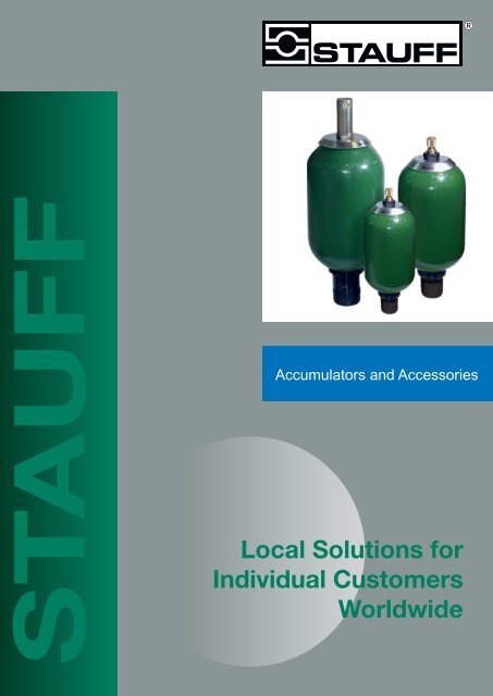
STAUFF<br />
Accumulators and Accessories<br />
<strong>Local</strong> <strong>Solutions</strong> <strong>for</strong><br />
<strong>Individual</strong> <strong>Customers</strong><br />
<strong>Worldwide</strong>
Walter Stauffenberg GmbH & Co. KG<br />
P.O.Box 1745 · D-58777 Werdohl<br />
Im Ehrenfeld 4 · D-58791 Werdohl<br />
Tel. : + 49 (0) 2392 916-0<br />
Fax: + 49 (0) 2392 2505<br />
e-mail: sales@stauff.com<br />
Internet: http://www.stauff.com<br />
Australia:<br />
Stauff Corporation (Pty.) Ltd.<br />
P.O. Box 227<br />
24-26 Doyle Avenue, Unanderra<br />
Wollongong, N.S.W.<br />
AUS-2526 Unanderra<br />
Tel. : + 61 2 42 71 18 77<br />
Fax: + 61 2 42 71 84 32<br />
Brazil:<br />
Stauff Brasil Ltda.<br />
Avenida Gupe 10.767<br />
Galpa˜ o 2, Bloco A<br />
WT – Empresarial Parque Castello Branco<br />
BRA-Barueri – SP<br />
CEP: 06422-120<br />
Tel: +55 1147899020<br />
Fax: +55 1147899021<br />
China:<br />
Stauff International Trading (Shanghai) Co., Ltd.<br />
Shangdian Mansion, Pudong<br />
331, Binzhou Road<br />
CHN-200126 Shanghai<br />
Tel. : + 86 21 58 45 65 60<br />
Fax: + 86 21 58 45 66 80<br />
France:<br />
Stauff s.a.<br />
230, Avenue du Grain d’Or<br />
Z.I. de Vineuil-Blois Sud<br />
F-41354 Vineuil-cedex<br />
Tel. : + 33 2 54 50 55 50<br />
Fax: + 33 2 54 42 29 19<br />
India:<br />
Stauff India Pvt. Ltd.<br />
Gat. No. 2340<br />
Pune-Nagar Road, Wagholi<br />
IND-Pune - 412207<br />
Tel. : + 91 20 705 19 90<br />
Fax: + 91 20 705 19 89<br />
Italy:<br />
Stauff Italia s.r.l.<br />
Via Pola 21/23<br />
I-20034 Birone di Giussano<br />
Tel. : + 39 0362 31 21 13<br />
Fax: + 39 0362 33 55 36<br />
Japan:<br />
Ohtsuka Tec. Co. Ltd.<br />
1-7-19 Minami Shinagawa<br />
Shinagawa-Ku<br />
JPN-Tokyo 140<br />
Tel. : + 81 3 34 72 12 01<br />
Fax: + 81 3 34 72 12 09<br />
Canada:<br />
Stauff Canada Ltd.<br />
866 Milner Avenue<br />
CAN-Scarborough, Ontario M1B 5N7<br />
Tel. : + 1 416 282 46 08<br />
Fax: + 1 416 282 30 39<br />
USA:<br />
Stauff Corporation<br />
7 Wm. Demarest Place<br />
USA-Waldwick, N.J. - 07463<br />
Tel. : + 1 201 444 78 00<br />
Fax: + 1 201 444 78 52<br />
United Kingdom:<br />
Stauff UK<br />
332, Cole<strong>for</strong>d Road<br />
Darnall<br />
GBR-Sheffield, S 9 5 P H<br />
Tel. : + 44 1142 518 518<br />
Fax: + 44 1142 518 519<br />
2<br />
Distributor<br />
<strong>Oil</strong> <strong>Solutions</strong><br />
PO Box 653 Castlemaine 3450<br />
Phone 0421 336 009<br />
Fax 03 9012 4332<br />
sales@oilsolutions.com.au<br />
www.oilsolutions.com.au<br />
Stauff Hydraulic Accessories<br />
Breathers<br />
Diffusers<br />
Flow Indicators<br />
Level Gauges<br />
Pressure Gauges<br />
Spin On Filters<br />
Suction Strainers<br />
Valves<br />
The STAUFF hydraulic accessories program has been<br />
carefully designed to offer a range of components suited to the<br />
demands of building hydraulic systems in most industrial and<br />
mobile applications.<br />
Whether you require simple filler breathers or precise electrical<br />
level switches, flow control valves or complete filter units; the<br />
STAUFF accessories range should provide you with the choice<br />
you need.<br />
At Stauff we are aware of the ongoing development and<br />
innovation within the hydraulic industry. We strive to keep up<br />
with and further develop the latest technology and to bring the<br />
benefit of any such improvements directly to the customer.<br />
Additionally we are always prepared to consider custom built<br />
products, if you have a special need.<br />
We ensure that your most urgent requirements are met by<br />
keeping a large and comprehensive stock in Australia<br />
These products are subject at all times to our DIN ISO 9001<br />
Quality Management Systems.
CONTENTS<br />
2<br />
Accumulators and Accessories<br />
PAGE<br />
Introduction .......................................................................................................................................3<br />
Material Options & Features ..........................................................................................................4,5<br />
Bladder Accumulators - STBA -<br />
Dimensions .......................................................................................................................................6<br />
Ordering Codes ................................................................................................................................7<br />
Diaphragm Accumulators - STDA -<br />
Dimensions .......................................................................................................................................8<br />
Ordering Codes ................................................................................................................................9<br />
Safety Blocks - STASB -<br />
General In<strong>for</strong>mation and Ordering Code ........................................................................................10<br />
Bladders - STB -<br />
Dimensions ..................................................................................................................................... 11<br />
Ordering Codes ................................................................................................................................7<br />
Anti-Extrusion Rings (AER) ............................................................................................................ 11<br />
Accessories<br />
Accumulator Adaptors ....................................................................................................................10<br />
Clamps and Brackets .....................................................................................................................12<br />
Charging Kit ....................................................................................................................................13<br />
Services and Sizing<br />
Precharging Procedure ..................................................................................................................14<br />
Maintenance, Disassembly and Reassembly .....................................................................15, 16, 17<br />
Accumulators Sizing Table <strong>for</strong> Storage Applications ......................................................................18
Introduction<br />
Accumulators and Accessories<br />
Accumulators provide a means of regulating the per<strong>for</strong>mance of a hydraulic system. They are suitable <strong>for</strong> storing<br />
energy under pressure, absorbing hydraulic shock, dampening pump pulsation and fl ow fl uctuations. Bladder or<br />
diaphragm accumulators provide excellent gas and fl uid separation ensuring dependable per<strong>for</strong>mance, maximum<br />
effi ciency, and long service life.<br />
Why use an Accumulator?<br />
• Improves your system effi ciency • Accepted world wide<br />
• Supplements your pump fl ow • High/ low temperature tolerance<br />
• Supplies extra power in an emergency • Extremely safe (cannot be disassembled under pressure)<br />
• Compensates <strong>for</strong> any system leakage • Quick response<br />
• Absorbs hydraulic shocks • Wide range of compounds <strong>for</strong> a variety of fl uids<br />
Accumulator Function<br />
The design of the Stauff accumulator makes use of the difference in the compressibility between a gas (nitrogen) and<br />
a liquid (hydraulic fl uids). The bladder contained in the shell is pre-charged with nitrogen gas to a pressure determined<br />
by the system pressure.<br />
After pre-charging, the work can be split into three steps.<br />
Step 1. When the hydraulic fl uid enters the accumulator, the nitrogen contained in the bladder is compressed and<br />
its pressure is increased.<br />
Step 2. The compression of the bladder stops when the pressure of the fl uid and nitrogen are equal (balanced).<br />
During this step the bladder is not subject to any abnormal mechanical stress.<br />
Step 3. On demand, as system pressure falls, the accumulator’s stored fl uid is returned to the system under<br />
pressure applied by the compressed nitrogen. On completion of the hydraulic system functions, the<br />
accumulator reverts to step 1.<br />
3
Material Options and Features<br />
4<br />
Main<br />
Components<br />
Shell<br />
Bladder<br />
<strong>Oil</strong> Port<br />
Assembly<br />
Accumulators and Accessories<br />
Standard<br />
Material<br />
• Chrome - Molybdenum<br />
Alloy Steel, (SA372)<br />
• All Sizes Comply with<br />
AS1210 Materials<br />
Specifi cations<br />
• Low temperature Buna-N<br />
(NBR)<br />
Material<br />
Options<br />
Consult Stauff<br />
Viton - (V)<br />
EPR - (E)<br />
Hi-Temp Buna (HBR)<br />
Consult Stauff <strong>for</strong><br />
other options<br />
• AISI 4130 material spec. Consult Stauff<br />
Bladder Accumulator Features Maximum Flow Rates<br />
• Meets AS1210 and AS4343 specifi cations<br />
• 4 –1 design factor at normal operating pressures.<br />
• Also available with <strong>for</strong>eign certifi cates (upon request)<br />
• Interchangeable with most competitor’s units.<br />
• All standard accumulators available from stock.<br />
Features<br />
• Seamless shell construction<br />
• Documentation to AS4343<br />
provided<br />
• Available with Foreign<br />
or Domestic Certifi cates<br />
(Consult Stauff)<br />
• 1 piece fully enclosed<br />
moulded bladder<br />
• With moulded steel valve<br />
stems<br />
• Wide range of operating<br />
temperatures<br />
• Proven design and reliability<br />
• Port options available, refer<br />
to ordering code<br />
Size (litres)<br />
Max. Recommended Flow<br />
LPM<br />
1 & 2.5 336<br />
4 564<br />
10 - 57 1176
Material Options and Features<br />
5<br />
1. Shell<br />
Bladder accumulator shells are made from chromemolybdenum<br />
alloy steel (SA372) with <strong>for</strong>ged ends<br />
<strong>for</strong> maximum strength. All sizes comply with AS1210<br />
material specifi cations, and documentation to AS4343<br />
are provided.<br />
Accumulators and Accessories<br />
2. Bladder<br />
Stauff bladders are manufactured from the most<br />
advanced elastomers which are capable of meeting<br />
a wide range of systems requirements. Bladders are<br />
offered in a variety of compounds to meet a, wide range<br />
of fl uids and operating temperatures. Standard material<br />
is low temperature Buna –N (NBR).<br />
3. Bladder Stems<br />
All bladder accumulators, sizes 4 litre and larger, are<br />
fi tted as standard with two-piece bladder stems with<br />
replaceable gas valve cartridge <strong>for</strong> ease of serviceability.<br />
4<br />
1<br />
2<br />
4. Port Assemblies<br />
Standard oil service ports are made from high-strength<br />
alloy steel <strong>for</strong> maximum durability.<br />
5. Fluid Ports<br />
BSPP(standard), NPT and Split Flange Adapters are<br />
available (See page 10). Bleeder ports (plugged) are<br />
included as standard on sizes 4 litre and larger.<br />
6. Gas Valve<br />
All accumulators are fi tted with a gas valve <strong>for</strong> ease of<br />
gas pre-charging. 4 litre and larger units are equipped<br />
with a cored gas valve cartridge<br />
(ISO-4570-8V1) <strong>for</strong> ease of maintenance. For safety, the<br />
gas valve will vent if unscrewed.<br />
6<br />
3<br />
5
6<br />
Accumulators and Accessories<br />
Stauff Bladder Accumulator Dimensions and Specifi cations<br />
Nominal<br />
Capacity<br />
(Litres)<br />
Max.<br />
W.P.<br />
(bar)<br />
Dimensions<br />
Net<br />
Weight<br />
A<br />
mm<br />
B<br />
mm<br />
C<br />
mm<br />
D<br />
BSPF<br />
F<br />
Bleed Plug<br />
Kg.<br />
1.1 400 117 321 55 G3/4” N/A 5.7<br />
2.5 400 118 522 54 G3/4” N/A 10<br />
4 345 168 446 65 G1 1/4” Hex 19 a/f 14<br />
10 210 222 585 103 G2” Hex 19 a/f 27<br />
20 210 222 891 103 G2” Hex 19 a/f 42<br />
25 210 222 1041 103 G2” Hex 19 a/f 55<br />
37 210 222 1428 103 G2” Hex 19 a/f 66<br />
50 210 222 1933 103 G2” Hex 19 a/f 92<br />
57 345 229 2003 103 G2” Hex 19 a/f 125
Accumulators and Accessories<br />
Stauff Bladder Accumulators Ordering Codes<br />
Model Code<br />
STBA - Stauff Bladder Accumulator<br />
STB - Bladder only<br />
Type<br />
O - <strong>Oil</strong> Service Bladder (Standard)<br />
W - Water Service Bladder (Optional)<br />
Other approvals on request<br />
Size<br />
Code<br />
Capacity<br />
Litres<br />
011 1.1<br />
025 2.5<br />
040 4<br />
10 10<br />
20 20<br />
25 25<br />
37 37<br />
50 50<br />
57 available in T style only 57<br />
Bladder Material<br />
NBR - Low Temp. Buna-N (Standard) 4 - 57L (-15 to 80˚C)<br />
HBR - High Temp Buna-N (Optional) (0 - 130˚C)<br />
V - Viton (Optional) (-20 to 140˚C)<br />
E - EPR (Optional) (-40 to 120˚C)<br />
Pressure Rating<br />
P3 - 3000 PSI / 210 Bar (Standard) 10 - 50L<br />
P5 - 5000 PSI / 345 Bar (Standard) 4 & 57L<br />
P6 - 6000 PSI / 400 Bar (Standard) 1.1 & 2.5L<br />
Fluid Port Connection<br />
B - BSPF Threaded (Std) 1.1 - 57L<br />
F - Code 62 Split Flange (Optional) 4 - 57L<br />
Available with Split Flange Adaptor **<br />
** Not available on water service<br />
Style<br />
B - Bottom Repairable (Standard)<br />
T - Top Repairable (Optional)<br />
Design Code<br />
1 - Standard (Australian Standard) AS 1210<br />
* - Special design No. to be assigned<br />
STBA - O - 011 - HBR - P3 - B - B - 1<br />
STB - O - 011 - HBR<br />
7
8<br />
Part No.<br />
Accumulators and Accessories<br />
Stauff Diaphragm Accumulators Dimensions and Specifi cations<br />
• Non-repairable diaphragm accumulator<br />
• Compression ratio of 8:1<br />
• Electron beam welded steel shell<br />
• Standard nitrile rubber high strength diaphragm<br />
• European certifi cation - CE<br />
• Optional M28x1.5 gas connection<br />
Volume<br />
Litres<br />
Pressure<br />
Bar<br />
Charging<br />
Thread<br />
Connection<br />
Dimensions (mm) Weight<br />
kg<br />
A B C D<br />
STDA - 032 - NBR - P3 - B - N - 1 0.32 210 G1⁄4” G1⁄2” 168 20 32 95 1.8<br />
STDA - 050 - NBR - P3 - B - N - 1 0.5 210 G1⁄4” G1⁄2” 180 22 41 106 2.1<br />
STDA - 075 - NBR - P3 - B - N - 1 0.75 210 G1⁄4” G1⁄2” 197 22 41 123 3<br />
STDA - 100 - NBR - P1 - B - N - 1 1 200 G1⁄4” G1⁄2” 208 22 41 136 3.6<br />
*<br />
*New 1/4” BSP gas valve<br />
connection <strong>for</strong> easy use with<br />
Stauff charging kit #STA-CK-1
Accumulators and Accessories<br />
Stauff Diaphragm Accumulators Ordering Code<br />
Model Code<br />
STDA - Stauff Diaphragm Accumulator<br />
Size<br />
Code<br />
Capacity<br />
Litres<br />
032 0.32<br />
050 0.5<br />
075 0.75<br />
100 1<br />
Diaphragm Material<br />
NBR - Low temp Buna - N (Standard) -15 to 80˚C<br />
Pressure Rating<br />
P1 - 2900 PSI/200 Bar (Standard) 1L<br />
P3 - 3000 PSI/210 Bar(Standard) 0.32,0.5,0.75L<br />
Fluid Port Connection<br />
B - G1/2 BSPF (Standard)<br />
Style<br />
N - Non Repairable (Standard)<br />
Design Code<br />
1 - Standard (Certifi ed European - CE)<br />
* - Special design No. to be assigned<br />
STDA - 032 - NBR - P3 - B - N - 1<br />
9
Safety Blocks<br />
10<br />
P<br />
Stauff Code<br />
Accumulators and Accessories<br />
• Constructed from hi-tensile steel<br />
• Provides manual isolation (ball valve) of the accumulator from the circuit<br />
• Factory set pressure relief valve<br />
• Manual integrated valve <strong>for</strong> fl uid dump to tank<br />
• CETOP connection to circuit. BSPP male fl ange adaptor on accumulator side<br />
• Stauff Test 20 coupling supplied <strong>for</strong> sampling or pressure monitoring<br />
• Safety blocks are also available with an electric dump valve option (AC/DC).<br />
Price on application<br />
• A range of sealing materials available<br />
Bore<br />
mm<br />
Isolation<br />
Accumulator<br />
Connection<br />
Recommeded Series<br />
Weight<br />
kg<br />
STASB-NG*-M-1-7-350 16 manual BSPM 1 1/4” 4 litre - 350 bar 5.6<br />
STASB-NG*-M-1-7-210 24 manual BSPM 2” (10 to 50 litre) - 210 bar 12.1<br />
STASB-NG*-M-1-7-350<br />
* Available in sizes 10, 20 & 32<br />
24 manual BSPM 2” (10 to 57 litre) - 345 bar 12.1<br />
Accumulator Adaptors<br />
T<br />
Description Stauff Code<br />
2” BSPP Plug with O-Ring STAP-0-32<br />
Reducing Bush 2” BSPPM x 1/2” BSPPF STRB-32-08<br />
Reducing Bush 2” BSPPM x 3/4” BSPPF STRB-32-12<br />
Reducing Bush 2” BSPPM x 1” BSPPF STRB-32-16<br />
2” Bonded Washer ATB036<br />
1/2” Bonded Washer ATB025<br />
3/4” Bonded Washer ATB027<br />
1” Bonded Washer<br />
SAE Flange Inserts with Captive Seals<br />
ATB030<br />
1/2”SAE Code 61 x 1/2” BSPPM STFI-3-0808M<br />
1/2” SAE Code 62 x 1/2” BSPPM STFI-6-0808M<br />
3/4” SAE Code 61 x 3/4” BSPPM STFI-3-1212M<br />
3/4” SAE Code 62 x 3/4 “ BSPPM STFI-6-1212M<br />
11/4” SAE Code 62 x 11/4” BSPPM<br />
SAE Flanges<br />
STFI-6-2020M<br />
Code 61, 1/2” Split Flange Pair SFC308<br />
Code 61 , 3/4” Split Flange Pair SFC312<br />
Code 61 , 11/4 “ Split Flange Pair SFC320<br />
Code 61, 2” Split Flange Pair SFC332<br />
Code 62, 1/2” Split Flange Pair SFC608<br />
Code 62, 3/4” Split Flange Pair SFC 612<br />
Code 62, 11/4” Split Flange Pair SFC 620
Bladder Dimension Tables<br />
Accumulators and Accessories<br />
Stauff offer a wide range of bladder materials to suit most applications. Please consult Stauff <strong>for</strong> details of bladder<br />
compatibility, with fl uid and fl uid temperature.<br />
Table 1 gives the range of bladder materials available with their corresponding working temperature when handling<br />
non-aggressive fl uids.<br />
Table 2 can be used to distinguish bladder capacities by overall dimensions. For other bladder materials consult<br />
Stauff.<br />
H<br />
D<br />
Interchangeability<br />
Anti Extrusion Ring Assembly<br />
Table 1<br />
Stauff Code Bladder Material<br />
Temperature Range<br />
from ˚C to ˚C<br />
NBR Low Temperature Buna-N(Standard) -15 80<br />
HBR High Temperature Buna-N 0 130<br />
V Fluorocarbon(Viton) -20 140<br />
E Ethylene Propylene (EPR) -40 120<br />
Table 2 Bladder kit<br />
Accumulator<br />
Capacity (l)<br />
Nominal<br />
Dimension<br />
H mm<br />
Dimension<br />
D mm<br />
0.16 154 41<br />
0.6 132 73<br />
1.1 147 91<br />
2.5 335 100<br />
4.0 203 142<br />
10.0 283 198<br />
20.0 610 198<br />
37.0 1128 198<br />
50.0 1603 198<br />
57.0 1703 198<br />
Stauff bladders are fully interchangeable with common European brands.<br />
• Anti extrusion ring (AER) assembly includes the moulded anti extrusion<br />
ring with split ring, fl uid port (or top plug) O-ring and back-up ring<br />
& bleed plug bonded seal <strong>for</strong> 4 to 57 litre.<br />
• <strong>Oil</strong> service AER supplied in nitrile carbon steel split ring (standard).<br />
For water service, AER incorporates a stainless steel split ring.<br />
Stauff Part No. Accumulator Size<br />
Connection to<br />
Accumulator BSPM<br />
STB-AER-01 1.1, 2.5L G3/4”<br />
STB-AER-02 4L G1 1/4”<br />
STB-AER-03 10 - 57L G2”<br />
Always quote full Part No. e.g.<br />
STB-O-011-NBR, capacity, Nitrile<br />
Rubber, 1/4” BSP.<br />
The kit comprises of :<br />
- Bladder<br />
- Gas valve<br />
- Lock nut<br />
- Fluid port ‘O’-Ring<br />
- Back up ring<br />
- Protective Cap*<br />
- Bleed plug seal*<br />
*4L capacity and above only<br />
Anti-extrusion ring assembly supplied<br />
separately, refer below.<br />
11
Clamps and Brackets<br />
Saddle Clamps<br />
Support Brackets<br />
12<br />
Accumulators and Accessories<br />
• Saddle clamps manufactured from mild steel with zinc<br />
plated fi nish<br />
• Rubber strips are made from nitrile<br />
• Support brackets manufactured from mild steel with zinc<br />
plated fi nish<br />
• Cushion rings made from nitrile<br />
4 litre<br />
10 - 57 litre<br />
Saddle Clamps Stauff Part Number<br />
1 to 3 litre AMP114<br />
4 litre AMP170<br />
10 to 57 litre AMP228<br />
Support Brackets Stauff Part Number<br />
4 litre BB120R<br />
10 to 57 litre BB170R
Charging Kit #STA-CK-1<br />
Accumulators and Accessories<br />
To maintain optimum per<strong>for</strong>mance in hydraulic systems employing accumulators, it is recommended that the gas<br />
pre-charge pressure be checked regularly. A loss in the gas pre-charge pressure will cause a drop in the system<br />
effi ciency and may cause damage to the accumulator bladder, diaphragm or piston.<br />
The charging kit allows hydro-pneumatic accumulators, whether bladder type, diaphragm type or piston type, to be<br />
charged with nitrogen to the desired pressure. For this purpose, the kit is connected to a commercially available<br />
nitrogen cylinder by a fl exible hose.<br />
The kit can also be used by technicians to check the current gas pre-charge pressure. The control valve incorporates<br />
a pressure gauge to permit direct pressure readings as well as a check valve to prevent back fl ow in the case of<br />
low pressures in the nitrogen cylinder. A manual bleed valve allows excess pressure to be reduced to the desired<br />
operating pre-charge level.<br />
- Pressure gauge is a safety pattern type to AS1349-1986<br />
The kit has adaptors to connect the hose to the nitrogen cylinder as well as adaptors to connect the control valve to the<br />
accumulator.<br />
SAA 10143 SAA 50019<br />
SAAGAS531 SAA 50510<br />
Note: Pictures not to scale.<br />
● Other adaptors available upon request.<br />
Order Code Description<br />
STA -CK -1<br />
Comprising of:<br />
Accumulator Charge Kit<br />
SAA50019 0.302 x 32 TPI adaptor<br />
SAA10143 7.8” UNF adaptor<br />
SAA50510 ¼” ISO 228 adaptor<br />
SAAGAS531 Type 50 - ¼” BSPT bottle adaptor<br />
SAA2069 Valve<br />
SAA2069T Valve tool<br />
SAAPC2156/250 Charging/pre - loading/gauge set<br />
SMS20/M ¼-2000AGAS Hose assembly - 2m<br />
- Optional: 0-17000 kPa outlet nitrogen regulator. Code SAR017000<br />
- Stauff recommend the use of nitrogen gas only <strong>for</strong><br />
pre-charging of accumulators.<br />
- Always wear protective safety glasses.<br />
SAA 2069<br />
SAA 2069T<br />
13
Precharging Procedure<br />
General In<strong>for</strong>mation<br />
14<br />
Accumulators and Accessories<br />
• Prior to commissioning a hydraulic system, any accumulators in the system should have their pre-charge<br />
pressure checked and adjusted.<br />
• The condition of the accumulator is primarily determined by periodic checking of the pre-charge pressure.<br />
• Hydraulic Accumulators are pressure vessels and only qualifi ed personnel should per<strong>for</strong>m maintenance.<br />
• Drain all fl uid completely from accumulator be<strong>for</strong>e per<strong>for</strong>ming any maintenance.<br />
• DO NOT weld or braze directly on accumulator shell.<br />
• DO NOT use automotive type valve cores as high pressure accumulator gas valves.<br />
• The most accurate pre-charge readings can only be taken when fl uid pressure is at zero.<br />
• Always observe the maximum working pressure and operating temperature ranges.<br />
Pre-charging Bladder Accumulators<br />
A Isolate the accumulator from the system, open the drain valve and make sure hydraulic fl uid pressure is zero.<br />
B Remove gas valve protection cap and valve cap from the accumulator.<br />
C To charge the accumulator, use a charging hose and gauge assembly from the Stauff Charging Kit # STA-CK-1<br />
rated <strong>for</strong> 250 bar maximum.<br />
D Be<strong>for</strong>e using the charging assembly (Figure 1.) make sure that valve A is completely open (counter-clockwise),<br />
and that bleed valve B (Figure 1.) is closed.<br />
E Connect the charging unit to the gas fi ll valve on the accumulator by means of knurled cap D (Figure 1.).<br />
F Fit the gas bottle adaptor (included in Stauff charging kit) to the nitrogen bottle, make sure that the gas valve on<br />
the nitrogen bottle is closed (see Figure 2.) then attach gas hose to the gas bottle adaptor on the nitrogen bottle.<br />
G Connect the other end of gas hose to the Stauff test coupling C (Figure 1.), after taking off its cap.<br />
H Turn valve A (Figure 1.) clockwise to the point where resistance is felt or pressure is registered on the<br />
gauge(only if there is an existing pre-charge).<br />
I SLOWLY open valve on nitrogen bottle (Figure 2.) and allow the gas to fl ow to the accumulator.<br />
J When the pressure in the accumulator is slightly higher than is required, close the valve on the nitrogen bottle.<br />
K Open valve A (Figure 1.) (counter-clockwise) and reduce the pressure in the gas hose and charging assembly to<br />
zero by means of bleed valve B (Figure 1.).<br />
L Remove hose from non-return Stauff test coupling C (Figure 1.) and replace cap.<br />
M Close the bleed valve B (Figure 1.) and wait a few minutes <strong>for</strong> pressure to stabilise.<br />
N Screw valve A (Figure 1.) clockwise until pressure can be read on gauge. This should be slightly higher than the<br />
required pressure.<br />
O Adjust pressure by means of bleed valve B (Figure 1.), then unscrew valve A (Figure 1.), counterclockwise.<br />
Open valve B (fi gure 1) then remove charging unit.<br />
P Replace gas valve cap and protective cap on accumulator. Accumulator is now ready <strong>for</strong> use.<br />
B<br />
A<br />
D<br />
C<br />
- Safety pattern gauge.<br />
Figure 1 Figure 2<br />
NOTE: Allow accumulator to rest about 10-15 minutes after gas pre-charging. This will allow gas temperature to adjust<br />
and equalize. Recheck gas pre-charge pressure and adjust if necessary. Check accumulator gas valve <strong>for</strong> any leaks<br />
with soapy water. Always wear safety glasses.
Maintenance<br />
Accumulators and Accessories<br />
General In<strong>for</strong>mation<br />
The condition of the accumulator is primarily determined by periodic checking of gas pre-charge pressure. Only<br />
qualifi ed personnel should per<strong>for</strong>m any maintenance on accumulators. Nitrogen gas pre-charge pressure should<br />
be checked at least once during the fi rst week of operation to ensure that no leak has developed. The pre-charge<br />
pressure and ambient temperature should be recorded at installation and checking done at the same temperature if<br />
possible. If there is no loss of gas pre-charge pressure, it should be rechecked in approximately 4 months. Thereafter,<br />
it should be checked annually. Check pre-charge if the system is acting sluggishly. If pre-charge is low, check gas<br />
valve <strong>for</strong> leakage and recharge.<br />
Bladder Accumulators<br />
1 Use appropriate valving in the hydraulic system to discharge all hydraulic fl uid from accumulator.<br />
2 To check or adjust pre-charge pressure, HYDRAULIC PRESSURE MUST BE REDUCED TO ZERO.<br />
Pre-charge pressure should be checked periodically.<br />
3 Charging and checking should be done with an accumulator charge kit similar to Stauff Part # STA-CK-1.<br />
4 Remove gas valve protection cap and valve cap as per pre-charge procedure instructions (B) on page 14<br />
5 Attach gauge assembly to accumulator gas valve.<br />
6 Make sure bleed valve B (Figure 1.) is closed, depress gas valve core gently by turning valve A (Figure 1.)<br />
clockwise. Gas pressure can now be read on gauge.<br />
7 To reduce pressure, open bleed valve B (Figure 1.) carefully, allowing gas to escape until desired pressure is<br />
obtained. It the pre-charging pressure is less than required, refer to the pre-charging procedure on page 14<br />
B<br />
A<br />
Figure 1<br />
D<br />
C<br />
- Safety pattern gauge.<br />
NOTE: Allow accumulator to rest about 10-15 minutes after gas pre-charging. This will allow gas temperature<br />
to adjust and equalize. Recheck gas pressure and adjust if necessary. Check accumulator gas valve <strong>for</strong> any<br />
leaks with soapy water.<br />
The kit has adaptors to connect the hose to the nitrogen cylinder as well as adaptors to connect<br />
the charging/pre-loading/gauge set to the accumulator.<br />
- Stauff recommend the use of nitrogen gas only <strong>for</strong><br />
pre-charging of accumulators.<br />
- Always wear protective safety glasses.<br />
15
Disassembly Instructions<br />
Bladder Type<br />
Remove protective cap<br />
Remove complete gas valve<br />
or gas valve core only<br />
Undo lock ring and remove<br />
fl ange washer<br />
Remove the fl uid port and<br />
bladder<br />
16<br />
1<br />
4<br />
7<br />
10<br />
Accumulators and Accessories<br />
NOTE: It is good practice to disassemble accumulators in a clean area<br />
to keep all parts free of <strong>for</strong>eign matter.<br />
Remove gas valve cap<br />
2<br />
5<br />
Remove locknut and metal label<br />
8<br />
Push fl uid port inside of shell<br />
and remove o-ring and back up<br />
ring<br />
Release nitrogen from the<br />
accumulator using Stauff<br />
charge kit #STA-CK-1<br />
Remove bleed plug<br />
(2 different models shown)<br />
3<br />
6<br />
9<br />
Squeeze the anti extrusion<br />
ring(AER) through the opening
Reassembly Instructions<br />
Bladder Type<br />
Neatly fold the bladder<br />
(logitudinally) and squeeze it<br />
inside the shell through the fl uid<br />
end. Locate the gas valve and<br />
push it through the opening at<br />
the gas end<br />
Pull the fl uid port through the<br />
AER. Assemble o-ring, backup<br />
ring, fl ange washer and locking<br />
ring (in that order)<br />
Tighten the bleed plug<br />
1<br />
4<br />
7<br />
Accumulators and Accessories<br />
NOTE: It is good practice to assemble accumulators in a clean area to<br />
keep all parts free of <strong>for</strong>eign matter.<br />
Remove the gas valve.<br />
Squeeze the bladder to<br />
discharge air from it. Lubricate<br />
the inside of the shell by turning<br />
it around on its axis. Use the<br />
process fl uid or similar liquid<br />
Ensure that the fl uid port is<br />
centred<br />
2<br />
5<br />
8<br />
Mount the metal plate. Tighten<br />
the locking nut (on the gas side)<br />
and fi t the gas valve or gas<br />
valve core<br />
Pace the fl uid port inside the<br />
shell (poppet fi rst). Fold and<br />
place it inside the shell so that<br />
metal components are located<br />
on the shell opening<br />
Tighten the locking ring<br />
3<br />
6<br />
NOTE:<br />
The steps outlined in the<br />
procedures above show the<br />
suggested sequence of events<br />
to carry out maintenance on<br />
accumulators utilising widely<br />
accepted general engineering<br />
fi tting practices and are not<br />
meant to be of a technical<br />
nature.<br />
These procedures may vary<br />
according to accumulator types<br />
17
Sizing Chart <strong>for</strong> Storage Applications<br />
Pressure<br />
Ratio<br />
P3/P1≤5<br />
Above volumes in litres discharged between P3/P2<br />
18<br />
Accumulators and Accessories<br />
The chart below is designed as a quick guide only <strong>for</strong> sizing of accumulators. It does not take into account actual<br />
isothermal or adiabatic conditions. For accurate system design requirements consult your Stauff Offi ce.<br />
STANDARD BLADDER ACCUMULATORS<br />
BLADDER ACCUMULATORS<br />
P3/P2 OB OF 11 O3 O4 10 20 28 37 50/54 57<br />
TRANSFER BARRIER WITH 50L GAS<br />
BACK-UP BOTTLE (BUB) FITTED<br />
28+ 1<br />
BUB<br />
37+ 1<br />
BUB<br />
37+ 2<br />
BUB<br />
54+ 1<br />
BUB<br />
54+ 1<br />
BUB P3/P2<br />
1.05 0.005 0.018 0.035 0.08 0.12 0.29 0.57 0.78 1.07 1.49 1.6 2.2 2.46 3.87 2.87 4.28 1.05<br />
1.10 0.01 0.035 0.066 0.14 0.22 0.34 1.09 1.49 2.03 2.84 3.03 4.18 4.69 7.37 5.49 8.16 1.1<br />
1.15 0.015 0.049 0.094 0.21 0.31 0.78 1.55 2.12 2.9 4.04 4.31 5.96 6.73 10.56 7.88 11.73 1.15<br />
1.20 0.019 0.063 0.12 0.26 0.39 0.98 1.97 2.69 3.68 5.13 5.48 7.58 8.6 10.06 14.97 1.2<br />
1.25 0.022 0.074 0.143 0.31 0.47 1.17 2.35 3.2 4.39 6.12 6.53 9.06 10.2 11.94 17.76 1.25<br />
1.30 0.026 0.086 0.149 0.36 0.54 1.35 2.69 3.68 5.03 7.02 7.49 11.91 13.94 1.3<br />
1.35 0.029 0.096 0.183 0.4 0.6 1.5 3.01 4.11 5.62 7.84 8.37 13.11 15.35 1.35<br />
1.40 0.032 0.104 0.201 0.44 0.66 1.65 3.29 4.51 6.16 8.6 9.17 16.77 1.4<br />
1.45 0.034 0.113 0.217 0.47 0.71 1.78 3.56 4.87 6.65 9.28 9.9 18.09<br />
1.50 0.036 0.121 0.231 0.5 0.76 1.9 3.8 5.2 7.11 9.98 10.58 19.33<br />
1.55 0.038 0.128 0.245 0.53 0.81 2.01 4.03 5.51 7.53 10.5 11.2 Above volumes in litres dischrged between P3/P2<br />
1.60 0.041 0.135 0.258 0.56 0.85 2.12 4.23 5.79 7.89 11.04 11.78<br />
HOW TO USE CHART ABOVE<br />
1.65 0.042 0.141 0.27 0.59 0.89 2.21 4.43 6.05 8.27 11.54 12.31<br />
1.70 0.044 0.146 0.28 0.61 0.92 2.3 4.6 6.3 8.6 12.01 12.81<br />
1. Use above chart in same way as left but<br />
limiting volume discharged to that shown, so<br />
1.75<br />
1.80<br />
0.046<br />
0.047<br />
0.152<br />
0.157<br />
0.29<br />
0.3<br />
0.63<br />
0.65<br />
0.95<br />
0.98<br />
2.38<br />
2.46<br />
4.77<br />
4.92<br />
6.52<br />
6.73<br />
8.91<br />
9.2<br />
12.44<br />
12.84<br />
13.27<br />
13.7<br />
that V1-V3 does not exceed 0.80 of actual<br />
accumulator shell volume.<br />
The corresponding pressure ratio is seen<br />
1.85 0.048 0.161 0.31 0.67 1 2.53 5.06 6.93 9.47 13.21 14.09<br />
under P3/P2 column.<br />
1.90 0.049 0.165 0.32 0.69 1.04 2.6 5.2 7.11 9.71 13.56 14.46 HOW TO USE THE CHART LEFT<br />
1.95 0.051 0.169 0.325 0.71 1.06 2.66 5.32 7.28 9.95 13.88 14.81<br />
Problem: What Size of Accumulator will<br />
2.00 0.052 0.173 0.331 0.72 1.09 2.72 5.44 7.44 10.17 14.19 15.14 discharge 1.4L of liquid between 140bar and<br />
2.10 0.054 0.179 0.344 0.75 1.13 2.83 5.65 7.73 10.56 14.74 15.72<br />
120bar.<br />
2.20 0.056 0.186 0.355 0.77 1.17 2.92 5.84 7.98 10.91 15.23 16.24<br />
140<br />
1. P3/P2 = 1.17<br />
120<br />
2.30 0.057 0.191 0.365 0.8 1.2 3 6 8.21 11.22 15.66 16.7 2. Find the value of P3/P2 which is equal<br />
2.40<br />
2.50<br />
0.059<br />
0.06<br />
0.195<br />
0.2<br />
0.374<br />
0.382<br />
0.82<br />
0.83<br />
1.23<br />
1.26<br />
3.07<br />
3.14<br />
6.18<br />
6.28<br />
8.41<br />
8.58<br />
11.49<br />
11.74<br />
16.04<br />
16.38<br />
17.11<br />
17.47<br />
to or next lowest to 1.17. In this case the<br />
value is 1.15.<br />
3. Select accumulator reference equal to or<br />
2.60 0.061 0.203 0.389 0.85 1.28 3.2 6.39 8.74 11.95 16.68 17.79 next greater to 1.4L from the values located<br />
in the row 1.15 i.e. 1.55 Project upwards<br />
2.70 0.062 0.207 0.395 0.86 1.3 3.25 6.5 8.88 12.15 16.95 18.07 and read off accumulator reference i.e. 20.<br />
2.80 0.063 0.21 0.401 0.87 1.32 3.29 6.59 9.01 12.32 17.19 18.33<br />
NOTES<br />
2.90 0.064 0.212 0.406 0.88 1.34 3.34 6.67 9.12 12.42 17.41 18.56<br />
3.00 0.065 0.215 0.411 0.89 1.35 3.37 6.75 9.22 12.61 17.6 18.77<br />
P3 = Maximum system pressure<br />
P2 = Minimum permitted system pressure<br />
3.20 0.066 0.219 0.419 0.91 1.38 3.44 6.88 9.4 12.85 17.94 19.12 P1 = 90% of P2<br />
3.40 0.067 0.222 0.425 0.92 1.4 3.49 6.98 9.54 13.04 18.2 19.41<br />
Volumes delivered based on<br />
P1V1 = P3V3 = Isothermal Compression<br />
3.60<br />
3.80<br />
0.068<br />
0.069<br />
0.224<br />
0.227<br />
0.43<br />
0.434<br />
0.94<br />
0.95<br />
1.41<br />
1.43<br />
3.53<br />
3.57<br />
7.06<br />
7.13<br />
9.65<br />
9.75<br />
13.2<br />
13.33<br />
18.42<br />
18.6<br />
19.64<br />
19.83<br />
P3V3n = P2V2n = Adiabatic Expansion<br />
where n = 1.4<br />
4.00 0.07 0.228 0.437 0.96 1.44 3.59 7.18 9.82 13.43 18.74 19.98<br />
4.50 0.075 0.231 0.443 0.97 1.46 3.64 7.28 9.45 13.61 18.98 20.24
NOTES<br />
Accumulators and Accessories<br />
19
STAUFF<br />
Australia<br />
HEAD OFFICE<br />
SYDNEY<br />
MELBOURNE<br />
24 - 26 Doyle Avenue<br />
27B Davis Road<br />
3B 14 - 16 White Street<br />
UNANDERRA NSW 2526<br />
WETHERILL PARK<br />
OAKLEIGH EAST VIC 3166<br />
P.O.Box 227<br />
NSW 2164<br />
P.O. Box 453<br />
UNANDERRA NSW 2526<br />
P.O. Box 7180<br />
MULGRAVE VIC 3170<br />
Ph: (02) 4271 1877<br />
WETHERILL PARK DC<br />
Ph: (03) 9543 5411<br />
Fax: (02) 4271 8432<br />
NSW 2164<br />
Fax: (03) 9543 5422<br />
E-mail: info@stauff.com.au<br />
Ph: (02) 9725 2733<br />
http://www.stauff.com.au<br />
Fax: (02) 9725 2744<br />
BRISBANE<br />
ADELAIDE<br />
463 Boundary Road<br />
1/3 Endeavour Drive<br />
RICHLANDS QLD 4077<br />
PORT ADELAIDE SA 5015<br />
P.O. Box 20<br />
P.O. Box 208<br />
RICHLANDS QLD 4077<br />
PORT ADELAIDE SA 5015<br />
Ph: (07) 3217 0444<br />
Ph: (08) 8341 2260<br />
Fax: (07) 3217 0300<br />
Fax: (08) 8341 1604<br />
New Zealand<br />
AUCKLAND<br />
Unit D 103 Harris Road<br />
EAST TAMAKI<br />
P.O. Box 58517<br />
GREENMOUNT<br />
Ph: (09) 271 4812<br />
Fax: (09) 271 4832<br />
E-mail: sales@stauff.co.nz<br />
http://www.stauff.com<br />
Distributed by:<br />
STA-AAA-0505AUS E & OE
Quality<br />
Endorsed<br />
Company<br />
ISO 9002 Lic 3765<br />
Standards Australia<br />
In-line<br />
FLOW MONITORS<br />
&<br />
CONTROLLERS<br />
Quality and Service<br />
worldwide
A<br />
In-Line Flow Monitors<br />
Stauff’s “FLOWTELL” in-line flow monitors and controllers offer a range of rugged flow rate gauges that<br />
are accurate and economical and are the perfect instruments <strong>for</strong> fixed in-line monitoring or <strong>for</strong> use as<br />
service tools <strong>for</strong> system commissioning.<br />
“FLOWTELL” employs the well-established and reliable ‘variable area orifice’ measurement method<br />
together with a unique ‘sharp edge technology’ that ensures low pressure drops and high tolerance<br />
levels to changes in viscosity, resulting in repeatable flow rate measurements <strong>for</strong> both liquids and gases.<br />
The product range is suitable <strong>for</strong> measuring Hydraulic <strong>Oil</strong>s, Water and Air or Gas mediums and includes<br />
models <strong>for</strong> Phosphate Ester. A special range is also available <strong>for</strong> High Temperature applications.<br />
“FLOWTELL”’ is also available with the option of field-adjustable single or twin switches <strong>for</strong> High and<br />
Low flow rate alarms, or as a Transmitter giving a 4 - 20mA signal <strong>for</strong> system control capability.<br />
To suit varying system demands, “FLOWTELL” monitors are available in a choice of materials comprising<br />
Aluminium, Brass or Stainless Steel with wetted parts materials to suit the fluid type.<br />
“FLOWTELL” is capable of working in any plane and is read against the Dual Scale on the outer sleeve<br />
by the external magnetically coupled non-invasive annular cursor.<br />
PERFORMANCE SPECIFICATIONS<br />
Measuring Accuracy: better than 4% Full Scale<br />
Repeatability: 1% of Full Scale<br />
Flow Range: Fluids 0.5 to 550 l/min (0.05 to 150 GPM)<br />
Gases 1.5 to1300 scfm (0.5 to 600 l/sec)<br />
Normal Viscosity Range: 1 to 150 cSt (mm 2 /sec)<br />
Working Pressures: Alu. & Brass 240 bar<br />
St. Steel 410 bar<br />
Temperature Range: Standard 116°C<br />
High Temp. 204°C (Ultra high on request - 315°C)<br />
Pressure Differentials: Refer to ∆P graphs on Page 3<br />
Standard Calibration: <strong>Oil</strong>: 40 cSt and 0.873 SG<br />
Water: tap water at 20°C and 1.0 SG<br />
Gas: air at 21°C and 7 bar<br />
Enclosure Rating: IP 65<br />
Electric Specifications:<br />
Flow Rate Alarm SPDT switch 10A 250VAC<br />
0.5A 125VDC<br />
0.25A 250VDC<br />
3A 125VAC bulb load<br />
Flow Rate Transmitter Power 12 - 35 VDC<br />
Output4 - 20mA, 0 -5 VDC, 1 - 5 VDC<br />
Over-current protection self-limiting at 35mA<br />
Resolution 10bit (0.1%)<br />
Isolation Inherently isolated from the process<br />
Response Time < 100 milliseconds<br />
2
Part Number Build <strong>for</strong> Ordering<br />
∆P - bar<br />
∆P - bar<br />
1.0<br />
0.8<br />
0.6<br />
0.4<br />
0.2<br />
0<br />
2.0<br />
1.75<br />
1.5<br />
1.25<br />
1.0<br />
0.75<br />
0.5<br />
0.25<br />
Port Sizes 3/8", 1/2"<br />
1<br />
7.5<br />
1 2<br />
In-Line Flow Monitors<br />
Type Material Pressure Fluid Port Size Scale<br />
FT B A 6 H 3 20<br />
2<br />
15 22.5<br />
5<br />
Type<br />
B Fluid Monitor<br />
G Gas Monitor<br />
H High Temp.<br />
M Single Switch<br />
N Twin Switch<br />
P Phosphate Est.<br />
R Transmitter<br />
Materials<br />
A Aluminium<br />
B Brass<br />
S Stainless Steel<br />
Pressure<br />
4 600psi (Gas, Alu. & Brass)<br />
5 1000psi (Gas, Stain. Steel)<br />
6 3500psi (Fluids, Alu. & Brass)<br />
7 6000psi (Fluids, Stain. Steel)<br />
Fluid Medium<br />
A Air / Gas<br />
H <strong>Oil</strong> / Hyd. Fluid<br />
W Water<br />
5<br />
30 37.5 45 52.5<br />
Flow Rate - l/min<br />
Port Sizes 3/8", 1/2"<br />
0 25 50 75 100 125 150<br />
Flow Rate - l/sec<br />
10<br />
10<br />
60<br />
∆∆∆∆∆P curves at 40cSt. – Fluid Monitors<br />
∆P - bar<br />
1.0<br />
0.82<br />
0.66<br />
0.5<br />
0.35<br />
0.18<br />
0<br />
Port Sizes 3/4", 1"<br />
20<br />
15<br />
38 75 115 150<br />
Flow Rate - l/min<br />
∆∆∆∆∆P curves at 7 bar. – Gas Monitors<br />
∆P - bar<br />
1.7<br />
1.5<br />
1.0<br />
0.5<br />
Port Sizes 3/4", 1"<br />
15<br />
20<br />
0 40 80 120 160 200 240<br />
Flow Rate l/sec<br />
3<br />
30<br />
25<br />
Scale Port Size Flow Range Flow Range<br />
BSPP Fluids Air<br />
25<br />
30<br />
40<br />
40<br />
GPM l/min SCFM l/sec<br />
01 3/8” 0.05 - 1 0.5 - 4 1.5 - 12 0.5 - 5.5<br />
02 3/8” 0.2 - 2 1 - 8 4 - 23 2 - 10<br />
05 1/2” 0.5 - 5 2 - 19 5 - 50 2.5 - 25<br />
10 1/2” 1 - 10 4 - 38 10 - 100 5 - 45<br />
15 3/4” 1 - 15 4 - 56 15 - 150 8 - 56<br />
20 3/4” 2 - 20 0 - 75 20 - 215 10 - 100<br />
25 3/4” 2 - 25 10 - 100 20 - 250 10 - 120<br />
30 1” 3 - 30 10 - 115 30 - 330 15 - 140<br />
40 1” 4 - 40 15 - 150 30 - 400 15 - 190<br />
50 1¼” 5 - 50 20 - 190 30 - 470 15 - 220<br />
75 1¼” 8 - 75 30 - 280 30 - 750 20 - 350<br />
88 1¼” 10 - 100 50 - 375 150 - 900 75 - 425<br />
99 1½” 20 - 150 10 - 550 150 - 1300 70 - 600<br />
∆P (bar)<br />
∆P - bar<br />
2.0<br />
1.73<br />
1.4<br />
1.0<br />
0.7<br />
Port Sizes 1¼", 1½"<br />
75<br />
0.35<br />
0 75 150<br />
50<br />
225 300 375 455 530 600<br />
Flow Rate - l/min<br />
2.0<br />
1.5<br />
1.0<br />
0.5<br />
0<br />
Port Sizes<br />
1 3/8” BSPP<br />
2 1/2” BSPP<br />
3 3/4” BSPP<br />
4 1” BSPP<br />
5 1¼” BSPP<br />
6 1½” BSPP<br />
Port Sizes 1¼", 1½"<br />
50<br />
75<br />
88<br />
88<br />
99<br />
A<br />
99<br />
100 200 300 400 500 600<br />
Flow Rate l/sec
PHYSICAL DETAILS<br />
Monitor Switch Alarm / Transmitter<br />
A<br />
D L<br />
Port Size “D” “L”<br />
3/8”, 1/2” 48 167<br />
3/4”, 1” 60 182<br />
1¼”,1½” 90 258<br />
MATERIAL SPECIFICATIONS<br />
Body Material<br />
L<br />
Port Size “L” “B” “W” “A”<br />
3/8”, 1/2” 167 101 56 47<br />
3/4”, 1” 182 114 75 47<br />
1¼”,1½” 258 135 47 47<br />
Aluminium Brass Stainless Steel<br />
Wetted Components<br />
Casing, Ports & Cone Aluminium Brass Stainless Steel<br />
Seals Buna-N Buna-N Viton with Teflon backup<br />
Transfer Magnet Teflon coated Alnico Teflon Coated Alnico Teflon Coated Alnico<br />
Floating Disc Stainless Steel Stainless Steel Stainless Steel<br />
Other Internal Parts Stainless Steel Stainless Steel Stainless Steel<br />
Non-wetted Components<br />
(Flow Monitors)<br />
Window Tube Polycarbonate Polycarbonate Polycarbonate<br />
Window Seals<br />
(Transmitters and Alarms)<br />
Buna-N Buna-N Buna-N<br />
Enclosure & cover Aluminium Aluminium Aluminium<br />
Seals Buna-N Buna-N Buna-N<br />
Window Pyrex Pyrex Pyrex<br />
DIN connector Polyamide Polyamide Polyamide<br />
N.B. (1) The outer polycarbonate window tube is a replaceable part in case damage or scratching<br />
makes visibility difficult. Contact Stauff <strong>for</strong> specific part numbers.<br />
(2) A digital readout is available <strong>for</strong> use with the transmitter to permit remote flow readings.<br />
STAUFF CORPORATION PTY LTD<br />
HEAD OFFICE<br />
24 - 26 Doyle Avenue<br />
UNANDERRA NSW 2526<br />
P.O. Box 227<br />
UNANDERRA NSW 2526<br />
Tel. (02) 4271 1877<br />
Fax.(02) 4271 8432<br />
E-mail: sales@stauff.com.au<br />
http://www.stauff.com<br />
ADELAIDE<br />
1/3 Endeavour Drive<br />
PORT ADELAIDE SA 5015<br />
P.O. Box 208<br />
PORT ADELAIDE SA 5015<br />
Tel. (08) 8341 2260<br />
Fax.(08) 8341 1604<br />
In-Line Flow Monitors<br />
Additional diagnostic equipment available from Stauff<br />
BRISBANE<br />
463 Boundary Road<br />
RICHLANDS QLD 4077<br />
P.O. Box 20<br />
RICHLANDS QLD 4077<br />
Tel. (07) 3217 0444<br />
Fax.(07) 3217 0300<br />
MELBOURNE<br />
3B 14 - 16 White Street<br />
OAKLEIGH EAST VIC 3166<br />
P.O. Box 453<br />
MULGRAVE VIC 3170<br />
Tel. (03) 9543 5411<br />
Fax.(03) 9543 5422<br />
W<br />
SYDNEY<br />
27B Davis Road<br />
WETHERILL PARK<br />
NSW 2164<br />
P.O. Box 7180<br />
WETHERILL PARK DC<br />
NSW 2164<br />
Tel. (02) 9725 2733<br />
Fax.(02) 9725 2744<br />
A<br />
B<br />
Proudly distributed by<br />
STAUFF CORPORATION<br />
(NZ) LTD<br />
AUCKLAND<br />
STAUFF CORP (NZ) Ltd<br />
Unit J 150 Harris Road<br />
EAST TAMAKI<br />
P.O. Box 58517<br />
GREENMOUNT<br />
Tel. (09) 271 4812<br />
Fax. (09) 271 4832<br />
E-mail: sales@stauff.co.nz<br />
S-FT 0802