combustion in a ramjet combustor with cavity flame holder kavi̇te ...
combustion in a ramjet combustor with cavity flame holder kavi̇te ...
combustion in a ramjet combustor with cavity flame holder kavi̇te ...

You also want an ePaper? Increase the reach of your titles
YUMPU automatically turns print PDFs into web optimized ePapers that Google loves.
Isı Bilimi ve Tekniği Dergisi, 30, 2, 57-68, 2010<br />
J. of Thermal Science and Technology<br />
©2010 TIBTD Pr<strong>in</strong>ted <strong>in</strong> Turkey<br />
ISSN 1300-3615<br />
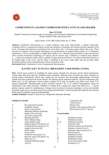
COMBUSTION IN A RAMJET COMBUSTOR WITH CAVITY FLAME HOLDER<br />
Onur TUNÇER<br />
İstanbul Technical University Faculty of Aeronautics and Astronautics Department of Aeronautical Eng<strong>in</strong>eer<strong>in</strong>g<br />
Maslak, İstanbul 34469, tuncero@itu.edu.tr<br />
(Geliş Tarihi: 10. 09. 2009, Kabul Tarihi: 08. 12. 2009)<br />
Abstract: Combustion characteristics <strong>in</strong> a <strong>ramjet</strong> <strong>combustor</strong> <strong>with</strong> <strong>cavity</strong> <strong>flame</strong>-<strong>holder</strong> is studied numerically.<br />
Combustor follows a constant area isolator section and comprises of hydrogen fuel <strong>in</strong>jected sonically upstream of the<br />
<strong>cavity</strong>. Secondary fuel <strong>in</strong>jection is performed at the <strong>cavity</strong> back wall. A diverg<strong>in</strong>g section follows the <strong>cavity</strong>. These<br />
concepts are utilized <strong>in</strong> many designs. Simulations were performed for an entrance Mach number of 1.4. Stagnation<br />
temperature is 702 K, correspond<strong>in</strong>g to a flight Mach number of 3.3. Detailed chemical k<strong>in</strong>etics is taken <strong>in</strong>to account<br />
<strong>with</strong> a reaction mechanism compris<strong>in</strong>g of 9 species and 25 reaction steps. Turbulence is modeled us<strong>in</strong>g Menter's<br />
shear stress transport model, which is suitable for high speed <strong>in</strong>ternal flows. It is observed that <strong>flame</strong> anchors at<br />
the lead<strong>in</strong>g edge of the <strong>cavity</strong>, and the <strong>flame</strong> is stabilized <strong>in</strong> the <strong>cavity</strong> mode rather than the jet-wake mode.<br />
Simulation captures all the essential features of the react<strong>in</strong>g flow field.<br />
Keywords:Ramjet, Combustion, Cavity, Computational fluid dynamics<br />
KAVİTE ALEV TUTUCULU BİR RAMJET YAKICISINDA YANMA<br />
Özet: Alev<strong>in</strong> kavite yardımı ile tutulduğu bir <strong>ramjet</strong> yanma odasında alev davranışı sayısal olarak <strong>in</strong>celenmiştir.<br />
Yanma odası sabit kesit alanlı bir izolatörün hemen ardındadır. Hidrojen yakıtı kaviten<strong>in</strong> akış yukarı yönünde ses<br />
hızında enjekte edilmektedir. İk<strong>in</strong>cil yakıt enjeksiyonu ise kaviten<strong>in</strong> arka duvarından sağlanmaktadır. Kaviten<strong>in</strong><br />
ardında kesit alanı genişleyen bir kesim bulunur. Bu yaklaşım birçok tasarımda kullanılır. Sayısal hesaplamalar giriş<br />
Mach sayısı 1.4 iç<strong>in</strong> yapılmıştır. Durma noktası sıcaklığı 702 K olup, bu koşullar uçuş Mach sayısı olarak 3.3’e<br />
karşılık gelmektedir. Hesaplamalarda ayrıntılı kimyasal k<strong>in</strong>etik 9 tür ve 25 tepkime basamağından oluşan bir<br />
mekanizma ile göz önüne alınmıştır. Türbülans ise yüksek hızlı iç akışlar iç<strong>in</strong> uygun olan Menter’<strong>in</strong> kayma<br />
gerilimi taşınımı modeli ile modellenmiştir. Sonuçta alev<strong>in</strong> kaviten<strong>in</strong> ön kenarına tutunduğu ve alev<strong>in</strong> jet ardındaki<br />
anafordan ziyade kavite içeris<strong>in</strong>de kararlı hale geldiği gözlemlenmiştir. Sayısal hesaplamalar tepkimeli akış alanının<br />
bütün önemli özellikler<strong>in</strong>i açığa çıkartabilmektedir.<br />
Anahtar Kelimeler: Ramjet, Yanma, Kavite, Hesaplamalı akışkanlar d<strong>in</strong>amiği<br />
NOMENCLATURE<br />
A Pre-exponential constant<br />
a1<br />
Modell<strong>in</strong>g constant<br />
C Species concentration<br />
D Molecular diffusion coefficient<br />
D Depth of the <strong>cavity</strong> [m]<br />
Ea<br />
Activation energy [cal]<br />
F1, F2 Blend<strong>in</strong>g functions<br />
h Static enthalpy [J/kg]<br />
H Total enthalpy [J/kg]<br />
J Diffused species flux [kg/(m 2 .s)]<br />
k Turbulent k<strong>in</strong>etic energy [m 2 /s 2 ]<br />
L Length of the <strong>cavity</strong> [m]<br />
M Mach number<br />
P Pressure [Pa]<br />
Pk<br />
Production term [kg/(m.s 3 )]<br />
Rk,m<br />
Reaction source term [kg/(m 3 .s)]<br />
S Stra<strong>in</strong> rate [s -1 ]<br />
Sct<br />
Turbulent Schmidt number<br />
t Time [s]<br />
57<br />
T Temperature [K]<br />
u Velocity [m/s]<br />
x Distance [m]<br />
y Distance to the nearest surface [m]<br />
Mass fraction of the m th species<br />
Ym<br />
Greek Symbols<br />
α Modell<strong>in</strong>g constant<br />
β *<br />
Modell<strong>in</strong>g constant<br />
β1, β2 Modell<strong>in</strong>g constants<br />
δij<br />
Kronecker delta<br />
λ Thermal conductivity [W/(m.K)]<br />
µ Dynamic viscosity [N.s/m 2 ]<br />
νt<br />
K<strong>in</strong>ematic eddy viscosity [m 2 /s]<br />
ρ Density [kg/m 3 ]<br />
σk<br />
Modell<strong>in</strong>g constant<br />
σω Modell<strong>in</strong>g constant<br />
Φ Modell<strong>in</strong>g constant<br />
ω Inverse time scale of eddy<br />
dissipation, [s -1 ]
Subscripts<br />
i, j, k, l Directions<br />
eff Effective<br />
ign Ignition<br />
m m th species<br />
0 Stagnation<br />
Superscripts<br />
- Time averaged value<br />
~ Favre averaged value<br />
INTRODUCTION<br />
Supersonic air breath<strong>in</strong>g propulsion systems are crucial<br />
for the demands of today's defense <strong>in</strong>dustry and future's<br />
high speed civilian transportation vehicles. On the other<br />
hand, as a direct consequence of high flow speeds, time<br />
necessary for <strong>in</strong>jection, mix<strong>in</strong>g, and subsequent<br />
<strong>combustion</strong> is m<strong>in</strong>imal, and is typically around 1 ms<br />
(Benyakar and Hanson, 2001). This poses significant<br />
challenges <strong>in</strong> the design of such propulsion systems.<br />
In order to successfully develop advanced air breath<strong>in</strong>g<br />
propulsion systems capable of high speed flight it is<br />
necessary to understand the fundamentals of mix<strong>in</strong>g and<br />
<strong>combustion</strong> processes <strong>with</strong><strong>in</strong> the <strong>combustor</strong>. Flame<br />
stabilization <strong>in</strong> high speed flows is a significant<br />
challenge that needs to be overcome. Studies performed<br />
primarily <strong>in</strong> the United States have demonstrated that<br />
“<strong>cavity</strong>” <strong>flame</strong> <strong>holder</strong>s could effectively be used both<br />
for <strong>ramjet</strong> and sc<strong>ramjet</strong> <strong>combustor</strong>s. The idea beh<strong>in</strong>d is<br />
that the <strong>cavity</strong> traps a strong and stable vortex <strong>with</strong><strong>in</strong><br />
and thereby provides favorable conditions for ignition<br />
(free radicals and temperature) result<strong>in</strong>g <strong>in</strong> a much<br />
decreased ignition delay time.<br />
Figure 1. Schematic View of the Combustor (Dimensions <strong>in</strong><br />
mm, Not to Scale).<br />
Cavity is a basic flow configuration that attracts both<br />
fundamental and practical <strong>in</strong>terest of researchers. A<br />
<strong>cavity</strong> is characterized by strong <strong>in</strong>ternal oscillations<br />
that are driven by the shear layer <strong>in</strong>stability (Benyakar<br />
and Hanson, 2001). Cold flow studies reveal that <strong>cavity</strong><br />
flows can be categorized <strong>in</strong>to two ma<strong>in</strong> regimes<br />
depend<strong>in</strong>g on the length to depth ratio of the<br />
<strong>cavity</strong>. Cavities hav<strong>in</strong>g a length to depth ratio of<br />
are often termed as ``open'' s<strong>in</strong>ce the<br />
upper shear layer re-attaches at the <strong>cavity</strong> back wall. On<br />
the other hand for small length to depth ratios<br />
cavities are called “closed” s<strong>in</strong>ce the<br />
separated free shear layer re-attaches the lower wall.<br />
Another aspect of <strong>cavity</strong> flows are the velocity and<br />
pressure fluctuations they exhibit. Experimental work<br />
58<br />
due to Zhang (1990) has shown that open cavities<br />
demonstrate either longitud<strong>in</strong>al or spanwise<br />
fluctuations. Some of these fluctuations are large<br />
bandwidth low amplitude typical of turbulent flows<br />
whereas some others have large amplitudes at dist<strong>in</strong>ct<br />
frequencies that depend on <strong>cavity</strong> geometry and external<br />
flow conditions. These are due to the acoustics of the<br />
<strong>cavity</strong>.<br />
Ignition and <strong>flame</strong> hold<strong>in</strong>g are the other important<br />
aspects of an <strong>in</strong>jection system that need to be taken <strong>in</strong>to<br />
account dur<strong>in</strong>g the design (Sung et al., 1999). Once the<br />
mixture is lit, the efficiency of <strong>combustion</strong> is directly<br />
related to the effectiveness of mix<strong>in</strong>g. Should there be<br />
enough free radicals to susta<strong>in</strong> <strong>combustion</strong>, it is<br />
considered that ignition is successful even though there<br />
might not be an appreciable amount of heat release<br />
(Benyakar and Hanson, 2001). In case there exists<br />
favorable conditions for ignition, the ignition length<br />
depends on the ignition delay time as<br />
, where denotes the flow speed of the<br />
medium. Therefore the ignition length necessary for<br />
high speed supersonic flows is much longer than<br />
conventional subsonic flows. It is for this very reason<br />
that the ma<strong>in</strong> goal of the <strong>flame</strong> <strong>holder</strong> <strong>in</strong> <strong>ramjet</strong>s and<br />
sc<strong>ramjet</strong>s is to provide a pool for free radicals <strong>in</strong> order<br />
to reduce the ignition delay time.<br />
There are a number of fuel <strong>in</strong>jection strategies<br />
recommended <strong>in</strong> the open literature for supersonic<br />
<strong>combustion</strong> (Abbitt et al., 1993; Hartfield, et al., 1994;<br />
Rigg<strong>in</strong>s et al., 1995; Rigg<strong>in</strong>s and Vitt, 1995; Fuller, et<br />
al., 1998). They all commonly focus on rapid near field<br />
mix<strong>in</strong>g. They unanimously rely on the generation of<br />
strong counter-rotat<strong>in</strong>g vortices propagat<strong>in</strong>g alongside<br />
the flow. As a consequence fuel air mix<strong>in</strong>g is enhanced<br />
<strong>in</strong> both small and large scales. On the other hand<br />
existence of good mix<strong>in</strong>g alone is not sufficient for a<br />
<strong>flame</strong> to be susta<strong>in</strong>ed all by itself.<br />
In this paper, numerical react<strong>in</strong>g flow field simulation<br />
of a <strong>ramjet</strong> <strong>combustor</strong> <strong>with</strong> <strong>cavity</strong> <strong>flame</strong> <strong>holder</strong> is<br />
presented. Geometry of the <strong>combustor</strong> is consistent <strong>with</strong><br />
the experimental work of Micka and Driscoll (2009). A<br />
schematic view is presented <strong>in</strong> Figure 1. A 402.50 mm<br />
long constant are isolator is utilized before the entry <strong>in</strong><br />
order to isolate the shock waves from the <strong>combustor</strong>.<br />
Cross section of the isolator is a rectangle that is 25.4<br />
mm wide <strong>in</strong> the out of plane direction <strong>with</strong> respect to<br />
Figure 1 and 38.1 mm high as shown <strong>in</strong> the<br />
aforementioned figure. A 12.7 mm deep and 50.8 mm<br />
long <strong>cavity</strong> section follows the isolator. Ma<strong>in</strong> fuel is<br />
<strong>in</strong>jected 44.5 mm upstream of this <strong>cavity</strong>. As the ma<strong>in</strong><br />
fuel jet <strong>in</strong>teracts <strong>with</strong> the oncom<strong>in</strong>g supersonic flow a<br />
bow shock is produced. Consequently the upstream<br />
boundary layer separates, thereby provid<strong>in</strong>g a region<br />
<strong>with</strong><strong>in</strong> which the boundary layer and jet fluids mix<br />
subsonically just upstream of the jet exit. In addition at<br />
the <strong>cavity</strong> back wall 6.0 mm high from the <strong>cavity</strong> floor a<br />
secondary fuel <strong>in</strong>jector is placed whose task is to<br />
provide more favorable conditions <strong>in</strong>side the <strong>cavity</strong> <strong>in</strong>
order to assist <strong>in</strong> <strong>flame</strong> hold<strong>in</strong>g. Just after the <strong>cavity</strong> a<br />
349 mm long diverg<strong>in</strong>g section follows. This section<br />
provides the area enlargement necessary to prevent<br />
thermal chok<strong>in</strong>g.<br />
When numerically solv<strong>in</strong>g chemically react<strong>in</strong>g flows,<br />
the accuracy of the chemical k<strong>in</strong>etic mechanism is yet<br />
another issue that cannot be overlooked through<br />
unphysical over-simplify<strong>in</strong>g assumptions such as quasi<br />
steady-state reaction assumptions. Especially for high<br />
speed react<strong>in</strong>g flows, characteristic time scales for the<br />
fluid flow are ever so much closer to the characteristic<br />
time scales associated <strong>with</strong> <strong>combustion</strong>. Combustion<br />
mechanism proceeds only as fast as the slowest<br />
oxidation step <strong>with</strong><strong>in</strong> the mechanism. Therefore, for<br />
these high-speed react<strong>in</strong>g flows <strong>with</strong><strong>in</strong> <strong>ramjet</strong>/sc<strong>ramjet</strong><br />
<strong>combustor</strong>s, Damköhler numbers are much smaller <strong>in</strong><br />
comparison to other <strong>combustion</strong> systems such as gas<br />
turb<strong>in</strong>e <strong>combustor</strong>s where<strong>in</strong> typical flow speeds are on<br />
the order of Mach 0.2 or so. For example Liu et al.<br />
(2006) used reduced chemical k<strong>in</strong>etic mechanisms for<br />
<strong>cavity</strong> stabilized ethylene-air <strong>flame</strong>s to predict <strong>flame</strong><br />
stability limits <strong>in</strong> supersonic flows based on<br />
experimental study. They have used 3, 10 and 15 step<br />
reduced chemical k<strong>in</strong>etic mechanisms respectively. In<br />
conclusion their results show that 15-step reduced<br />
model predicts experimental data much better than the 3<br />
and 10-step models. Therefore the importance of<br />
<strong>in</strong>clud<strong>in</strong>g accurate chemical k<strong>in</strong>etics is demonstrated.<br />
Based on this observation, <strong>in</strong> this paper when model<strong>in</strong>g<br />
hydrogen oxidation, extensive care is taken to <strong>in</strong>clude<br />
all important reactions and species so as to get accurate<br />
results. More detail about the reaction mechanism is<br />
provided <strong>in</strong> the follow<strong>in</strong>g section.<br />
MATHEMATICAL MODELLING<br />
It is possible to describe the flow <strong>with</strong><strong>in</strong> the <strong>ramjet</strong><br />
<strong>combustor</strong> as a chemically react<strong>in</strong>g, s<strong>in</strong>gle phase, multispecies<br />
flow. Then the govern<strong>in</strong>g equations for such a<br />
flow are Navier-Stokes equations coupled <strong>with</strong><br />
species conservation equations <strong>with</strong> be<strong>in</strong>g the number<br />
of species considered. In order to solve the flow the<br />
follow<strong>in</strong>g set of equations need to be solved<br />
simultaneously. Discretization and solution schemes are<br />
later discussed at the end of this section.<br />
Conservation Equations<br />
Here the set of conservation equations (mass,<br />
momentum, species and energy) that need to be<br />
accounted for are presented.<br />
Global cont<strong>in</strong>uity equation for compressible flow can be<br />
written as <strong>in</strong> Eq. 1 us<strong>in</strong>g tensor notation.<br />
Similarly the momentum equation is written as <strong>in</strong> Eq. 2,<br />
(1)<br />
59<br />
where,<br />
(2)<br />
In Eq. 3 is a modell<strong>in</strong>g parameter referred to as<br />
eddy viscosity. Its calculation is further discussed <strong>in</strong><br />
turbulence modell<strong>in</strong>g section.<br />
The follow<strong>in</strong>g n<strong>in</strong>e species are considered <strong>with</strong><strong>in</strong> the<br />
flow field; N2, H, H2, O, O2, OH, H2O, HO2 and H2O2.<br />
For each species, Eq. 4 needs to be solved separately.<br />
Chemical source term appear<strong>in</strong>g <strong>in</strong> this equation is<br />
obta<strong>in</strong>ed from the k<strong>in</strong>etic model. Turbulent Schmidt<br />
number is taken as 1.0.<br />
(3)<br />
(4)<br />
Conservation of energy equation is provided <strong>in</strong> Eq. 5<br />
<strong>with</strong> viscous dissipation be<strong>in</strong>g neglected. Turbulent<br />
Prandtl number is also assumed to be unity like the<br />
Schmidt number. Species enthalpies are computed us<strong>in</strong>g<br />
Jo<strong>in</strong>t Army Navy Air Force (JANAF) thermodynamic<br />
tables (Stull and Prophet, 1971).<br />
Us<strong>in</strong>g ideal gas law Eq. 6 as the equation of state,<br />
conservation equations can now be closed. Here<br />
is the gas constant of the mixture.<br />
Turbulence Modell<strong>in</strong>g<br />
(5)<br />
(6)<br />
In order to model eddy viscosity and other turbulent<br />
parameters, a turbulence model is necessary. For this<br />
purpose Menter's SST (shear stress transport)<br />
model is utilized (Menter, 1994). This particular model<br />
is suitable for high speed <strong>in</strong>ternal flows such as the one<br />
studied here (Javed and Chakraborty, 2006).<br />
Montgomery et al. (2003) and Liu et al. (2006) also<br />
used this model to <strong>in</strong>vestigate similar high speed<br />
react<strong>in</strong>g flows for <strong>ramjet</strong>/sc<strong>ramjet</strong> <strong>combustor</strong>s. Tam et<br />
al. (1999) used this turbulence model to jets <strong>in</strong><br />
supersonic cross flows. This is precisely the case for the<br />
ma<strong>in</strong> fuel jet <strong>in</strong>jection <strong>in</strong> the present paper. Furthermore,
experimental evidence about the validity of this model<br />
and comparison <strong>with</strong> other models is provided by Tong<br />
and Luke (2004). On the other hand, a known drawback<br />
of this model is that it tends to exaggerate turbulence<br />
levels <strong>in</strong> regions <strong>with</strong> large normal stra<strong>in</strong>, such as<br />
stagnation regions or regions of high acceleration. Yet<br />
this tendency is not as severe as it is <strong>in</strong> the orig<strong>in</strong>al<br />
underly<strong>in</strong>g model.<br />
The SST turbulence model is derived by blend<strong>in</strong>g the<br />
model applied to the <strong>in</strong>ner region of the turbulent<br />
boundary layer <strong>with</strong> a high Reynolds number form of<br />
the turbulence model (Shih et al., 1995) by<br />
transform<strong>in</strong>g it <strong>in</strong>to and variables which are applied<br />
to the outer portion of the turbulent boundary layer<br />
(Menter, 1994). A weight of is first assigned to the<br />
<strong>in</strong>ner model, while a weight of is<br />
applied to the outer high Reynolds number model.<br />
This approach <strong>in</strong>corporates advantages of each model<br />
<strong>in</strong>to the new SST model. Derivation of the model<br />
equations are skipped and the f<strong>in</strong>al form of the transport<br />
equations for the turbulent k<strong>in</strong>etic energy , and <strong>in</strong>verse<br />
time scale of eddy dissipation are provided <strong>in</strong> Eq. 7<br />
and <strong>in</strong> Eq. 8 respectively.<br />
The production term appear<strong>in</strong>g <strong>in</strong> the above<br />
equations is given <strong>in</strong> Eq. 9.<br />
(7)<br />
(8)<br />
(9)<br />
Coefficients of this new model are a l<strong>in</strong>ear comb<strong>in</strong>ation<br />
of the correspond<strong>in</strong>g coefficients of the orig<strong>in</strong>al<br />
underly<strong>in</strong>g models. Therefore these new coefficients are<br />
obta<strong>in</strong>ed simply as <strong>in</strong> Eq. 10.<br />
(10)<br />
All modell<strong>in</strong>g constants are listed <strong>in</strong> Table 1 for<br />
convenience.<br />
60<br />
Table 1. Modell<strong>in</strong>g Constants for the SST Turbulence<br />
Model.<br />
5/9<br />
0.44<br />
3/40<br />
0.0828<br />
0.09<br />
2<br />
1<br />
2<br />
0.856<br />
By us<strong>in</strong>g a limiter function for the formulation of eddy<br />
viscosity the proper transport behavior to predict<br />
separation is obta<strong>in</strong>ed as per Eq. 11. The value of<br />
constant equals to .<br />
<strong>with</strong>,<br />
(11)<br />
(12)<br />
is also a blend<strong>in</strong>g function like , whose purpose is<br />
to conf<strong>in</strong>e the limiter to the wall boundary layer s<strong>in</strong>ce<br />
the underly<strong>in</strong>g assumptions are <strong>in</strong>correct for free shear<br />
flows. <strong>in</strong> Eq. 13 is an <strong>in</strong>variant measure of stra<strong>in</strong><br />
rate.<br />
(13)<br />
Blend<strong>in</strong>g functions determ<strong>in</strong>e the success of this<br />
method. They depend both on the distance to the nearest<br />
surface and also on the flow variables. First blend<strong>in</strong>g<br />
function is provided <strong>in</strong> Eq. 14.<br />
where,<br />
<strong>with</strong>,<br />
Second blend<strong>in</strong>g function is provided <strong>in</strong> Eq.17.<br />
where,<br />
(14)<br />
(15)<br />
(16)<br />
(17)<br />
(18)
Table 2. K<strong>in</strong>etic data for the reaction mechanism (units are <strong>in</strong> cm,mol,s,K,cal).<br />
Reaction A n Reference<br />
1. 1.0 0.0 Warnatz, 1984<br />
2. 1.0 0.0 Tsang et al.,1986<br />
3. 2.70 6260 Natarajan et al., 1987<br />
4. 0.0 0.0 Warnatz, 1984<br />
5. 2.0 4000 Tsang et al., 1986<br />
6. 0.86 0.0 Frenklach et al., 1992<br />
7. 1.24 0.0 Davidson et al., 1996<br />
8. 0.760 0.0 Frenklach et al., 1992<br />
9. 1.24 0 Davidson et al., 1996<br />
10. 0.6707 17041 Yu et al., 1994<br />
11. 1.0 0 Warnatz, 1984<br />
12. 0.6 0 Frenklach et al., 1992<br />
13. 1.25 0 Frenklach et al., 1992<br />
14. 2.0 0 Tsang et al., 1986<br />
15. 0 671 Dixon Lewis, 1987<br />
16. 0 1068 Warnatz, 1984<br />
17. 0 635 Warnatz, 1984<br />
18. 2 5200 Tsang et al., 1986<br />
19. 0 3600 Warnatz, 1984<br />
20. 1.51 3430 Michael et al., 1988<br />
21. 0.370 0 Zellner et al., 1988<br />
0.9 1700<br />
22. 2.4 2110 Woolridge et al., 1994<br />
23. 0 500 Keyser, 1988<br />
0 427<br />
0 29410<br />
24. 0 1630 Hippler et al., 1990<br />
0 12000<br />
25. 0 17330 Hippler et al., 1995<br />
Third Body Efficiencies<br />
a. ,<br />
b. ,<br />
c. ,<br />
d. ,<br />
e. ,<br />
f. ,<br />
Troe Parameters for f<br />
, ,<br />
,<br />
Combustion Modell<strong>in</strong>g<br />
In a multi-reaction environment, the challenge is often<br />
to def<strong>in</strong>e the m<strong>in</strong>imum number of reactions necessary to<br />
represent the important characteristics of the <strong>flame</strong>.<br />
Here on the other hand an extensive set of reactions is<br />
used <strong>in</strong> order to resolve all the important <strong>in</strong>termediate<br />
species and free radicals as they play an important role<br />
<strong>in</strong> the ignition/ext<strong>in</strong>ction mechanism. Combustion<br />
mechanism used to model hydrogen <strong>combustion</strong><br />
consists of 25 reactions <strong>with</strong> 9 species. A list of<br />
reactions and associated parameters are presented <strong>in</strong><br />
Table 2. This reaction mechanism is a subset of GRI 3.0<br />
61<br />
mechanism (Smith et al., 1999). Nitrogen gas (N2) is<br />
<strong>in</strong>ert and therefore does not participate<br />
<strong>in</strong> any reaction, although it affects the rates of some<br />
reactions act<strong>in</strong>g as a third body.<br />
(19)<br />
K<strong>in</strong>etic rate of change of a species is described by an<br />
Arrhenius rate expression. The source term for each<br />
species is ultimately determ<strong>in</strong>ed from the summation of<br />
the change <strong>in</strong> that particular species from all<br />
contribut<strong>in</strong>g reactions. Other forms may be more<br />
appropriate depend<strong>in</strong>g upon the reaction. It is quite
common to have concentration dependencies for gas<br />
species other than those <strong>in</strong>volved <strong>in</strong> the reaction (Javed<br />
and Chakraborty, 2006).<br />
Numerical Schemes and Computational Grid<br />
Compressible Navier-Stokes equations, together <strong>with</strong><br />
the energy and phase equations, are solved us<strong>in</strong>g<br />
OpenFOAM. OpenFOAM is a C++ code library of<br />
classes for writ<strong>in</strong>g CFD codes (Jasak, 2007). These<br />
equations are discretized us<strong>in</strong>g the f<strong>in</strong>ite volume<br />
method, where the doma<strong>in</strong> is divided <strong>in</strong>to cells.<br />
Integration of the dependent variables over each cell,<br />
together <strong>with</strong> the application of Gauss theorem,<br />
generates a set of discretized equations <strong>with</strong> the<br />
divergence terms represented as fluxes across the cell<br />
faces, are evaluated us<strong>in</strong>g appropriate <strong>in</strong>terpolation<br />
schemes; here a l<strong>in</strong>ear <strong>in</strong>terpolation is utilized. Time<br />
<strong>in</strong>tegration is carried out us<strong>in</strong>g SUNDIALS libraries<br />
(H<strong>in</strong>dmarsh v.d., 2005) developed at Lawrence<br />
Livermore National Laboratory. Robustness of the ODE<br />
solver allows tak<strong>in</strong>g large time steps. At least an order<br />
of magnitude speed up is observed when compared to<br />
built-<strong>in</strong> ODE solver libraries of OpenFOAM. This cuts<br />
computation time considerably. Follow<strong>in</strong>g the<br />
procedure of Rhie and Chow (1983), discretisation of<br />
the term is left; a Poisson equation is constructed,<br />
and the equation set solved sequentially us<strong>in</strong>g the<br />
result<strong>in</strong>g PISO (pressure implicit splitt<strong>in</strong>g operator)<br />
algorithm (Issa, 1986). Solution is performed implicitly<br />
by matrix <strong>in</strong>version us<strong>in</strong>g “<strong>in</strong>complete Cholesky<br />
conjugate gradient” methods.<br />
Figure 2. Computational Grid <strong>in</strong> the Vic<strong>in</strong>ity of the Cavity<br />
Region (Not to Scale).<br />
While simulat<strong>in</strong>g wave dom<strong>in</strong>ated high Mach number<br />
flows such as the one <strong>in</strong>vestigated here, it is necessary<br />
to have appropriate boundary conditions that do not<br />
reflect waves. Walls naturally reflect waves, while <strong>in</strong>lets<br />
and outlets should not be reflective. Therefore at the<br />
outlet a wave transmissive boundary condition is used <strong>in</strong><br />
accordance <strong>with</strong> Po<strong>in</strong>sot and Lele (1992) and the farfield<br />
pressure is specified to be atmospheric. At the<br />
<strong>in</strong>lets temperature and total pressure are specified and<br />
velocities are computed from these specifications. This<br />
approach assures proper treatment of boundary<br />
conditions also assur<strong>in</strong>g conservation of mass <strong>with</strong><strong>in</strong> the<br />
computational doma<strong>in</strong> as well. For the turbulent k<strong>in</strong>etic<br />
energy boundary condition at the air <strong>in</strong>let turbulence<br />
<strong>in</strong>tensity is assumed. Inverse time scale of eddy<br />
dissipation is also chosen accord<strong>in</strong>gly <strong>with</strong> the<br />
characteristic length scale of turbulence at the <strong>in</strong>let. In<br />
order to ensure numerical stability, the solution of the<br />
62<br />
non-react<strong>in</strong>g flow is fed as the <strong>in</strong>itial condition to the<br />
react<strong>in</strong>g flow solver. As for the ma<strong>in</strong> fuel <strong>in</strong>jection<br />
location the upstream total pressure is specified high<br />
enough such that flow is choked at the <strong>in</strong>jection site as<br />
desired. Moreover, for the <strong>cavity</strong> backwall <strong>in</strong>jection site,<br />
the <strong>in</strong>jection velocity is specified as the boundary<br />
condition.<br />
In order to start the reaction, enthalpy of certa<strong>in</strong> ignition<br />
sites (two or three locations <strong>in</strong> the vic<strong>in</strong>ity of the <strong>flame</strong><br />
hold<strong>in</strong>g <strong>cavity</strong>) are multiplied by a factor greater than<br />
one (typically 1.5), if the temperature at that ignition<br />
site is below 2000 K, for a certa<strong>in</strong> duration until the<br />
<strong>flame</strong> is self-susta<strong>in</strong><strong>in</strong>g. This approach emulates a spark<br />
at that ignition cite. Rais<strong>in</strong>g the temperature directly<br />
often results <strong>in</strong> errors <strong>with</strong> the JANAF thermo-dynamics<br />
database as the temperature can <strong>in</strong>stantaneously go<br />
above the upper limit for the curve-fitt<strong>in</strong>g polynomial,<br />
therefore enthalpy is used as a proxy.<br />
A total of 0.15 million grid po<strong>in</strong>ts were used for<br />
simulations <strong>with</strong> f<strong>in</strong>er mesh <strong>in</strong> the <strong>cavity</strong> and upstream<br />
fuel <strong>in</strong>jection locations. Computational grid is twodimensional<br />
and is sufficient to capture the essential<br />
features of the flowfield such as the flow re-circulation<br />
<strong>in</strong> the <strong>cavity</strong>, shock reflections <strong>with</strong><strong>in</strong> the <strong>combustor</strong><br />
and the bow shock produced due to ma<strong>in</strong> fuel <strong>in</strong>jection.<br />
Grid structure at the vic<strong>in</strong>ity of the <strong>cavity</strong> is shown <strong>in</strong><br />
Figure 2. Note the ref<strong>in</strong>ed mesh structure <strong>in</strong>side the<br />
<strong>cavity</strong>.<br />
NUMERICAL RESULTS<br />
Air <strong>with</strong> a mass flow rate of enters the isolator<br />
section at a Mach number of 1.4. Stagnation<br />
temperature of the air enter<strong>in</strong>g the <strong>combustor</strong> is .<br />
Flow condition <strong>in</strong>vestigated is tabulated <strong>in</strong> Table 3.<br />
Especially at low to moderate flight Mach numbers,<br />
such as the flow condition <strong>in</strong>vestigated here, the<br />
temperature of the <strong>in</strong>com<strong>in</strong>g air is not sufficient to<br />
ignite the fuel all by itself. With these conditions a<br />
preferential location <strong>with</strong> a favorable equivalence ratio,<br />
temperature, pressure and velocity must exist such that<br />
the fuel can ignite. A rich radical pool is conta<strong>in</strong>ed <strong>in</strong><br />
this very region that is crucial <strong>in</strong> <strong>flame</strong> hold<strong>in</strong>g.<br />
Hydrogen (H2) is selected as the fuel due to its reduced<br />
characteristic <strong>combustion</strong> times. Fuel <strong>in</strong>jection is split<br />
<strong>in</strong>to two locations <strong>in</strong> order to aid <strong>in</strong> <strong>flame</strong> hold<strong>in</strong>g <strong>in</strong>side<br />
the <strong>cavity</strong>. Ma<strong>in</strong> fuel at a flow rate of is <strong>in</strong>jected<br />
sonically from the lower wall 44.5 mm upstream of the<br />
<strong>cavity</strong> lead<strong>in</strong>g edge. 33% of the total fuel flow is<br />
<strong>in</strong>jected at the <strong>cavity</strong> back wall to atta<strong>in</strong> a more<br />
desirable equivalance ratio <strong>in</strong>side the <strong>cavity</strong>. Fuel is<br />
<strong>in</strong>jected at a temperature of . Note that the flow at<br />
the upstream <strong>in</strong>jection port is choked. This is typically<br />
the case <strong>in</strong> many <strong>ramjet</strong>/sc<strong>ramjet</strong> <strong>combustor</strong>s as it easily<br />
allows to ma<strong>in</strong>ta<strong>in</strong> a constant fuel flow rate.
Table 3. Flow Parameters for Air and Hydrogen.<br />
Air Hydrogen Hydrogen<br />
(Upstream) (Cavity)<br />
3.4 0.002 0.001<br />
702 300 300<br />
1.4 1.0 0.5<br />
0.8 3.9 3.9<br />
The react<strong>in</strong>g flow field <strong>in</strong> the <strong>ramjet</strong> <strong>combustor</strong> has<br />
been simulated by solv<strong>in</strong>g two-dimensional Navier-<br />
0.975<br />
0.87<br />
1.08<br />
1.185<br />
1.185<br />
1.395<br />
1.08<br />
1.605<br />
1.5<br />
1.29<br />
1.605<br />
1.5<br />
1.395<br />
1.395<br />
63<br />
Stokes equations <strong>with</strong> shear stress transport (SST)<br />
turbulence model us<strong>in</strong>g open source CFD software<br />
OpenFOAM (Jasak, 2007). Other open source<br />
numerical libraries, such as SUNDIALS (H<strong>in</strong>dmarsh et<br />
al., 2005) for the <strong>in</strong>tegration of ord<strong>in</strong>ary differential<br />
equations (ODEs), are also used for the solution.<br />
Detailed chemistry <strong>with</strong> 9 species and 25 reaction steps<br />
is taken <strong>in</strong>to account for the <strong>combustion</strong> of hydrogen<br />
fuel.<br />
1.29<br />
1.185<br />
1.08<br />
1.29<br />
-50 0 50 100<br />
X (mm)<br />
Figure 3. Pressure Distribution near the Cavity Region (Pressures <strong>in</strong> MPa)<br />
Figure 3 demonstrates the qualitative features of the<br />
flow field through pressure distribution. Appearance of<br />
a bow shock due to upstream fuel <strong>in</strong>jection is also seen.<br />
Due to this bow shock upstream boundary layer<br />
separates from the lower wall and as a consequence of<br />
this separation a region <strong>with</strong><strong>in</strong> which the boundary layer<br />
fluid (air) mixes <strong>with</strong> the jet fluid (fuel) subsonically<br />
just near the <strong>in</strong>jection location is formed. It is also<br />
known that an oblique shock wave jet <strong>in</strong>teraction<br />
enhances mix<strong>in</strong>g between supersonic airflow and<br />
gaseous fuel through the vorticity generated by the<br />
barocl<strong>in</strong>ic torque. This <strong>in</strong> turn has immediate<br />
ramification on the jet spread<strong>in</strong>g rate and due to<br />
enhanced mix<strong>in</strong>g <strong>combustion</strong> efficiency is also<br />
enhanced as well. Formation of another shock wave at<br />
the <strong>cavity</strong> trail<strong>in</strong>g edge, where the flow beg<strong>in</strong>s<br />
expand<strong>in</strong>g, is also clearly visible from Figure 3. This<br />
shock wave at the trail<strong>in</strong>g edge is due to the flow reattachment<br />
and is therefore often referred to as the reattachment<br />
shock. In this particular case the reattachment<br />
shock is a rather strong one. In general while<br />
design<strong>in</strong>g <strong>ramjet</strong>/sc<strong>ramjet</strong> <strong>combustor</strong>s this re-attachment<br />
shock is sought to be made as weak as possible <strong>in</strong> order<br />
to obta<strong>in</strong> maximum thrust from the propulsion device.<br />
Shock reflections are also clearly seen from this figure.<br />
These are due to the supersonic nature of the flow.<br />
Surface pressure distribution at the top surface is plotted<br />
<strong>in</strong> Figure 4. Pressure distribution is demonstrated for<br />
both react<strong>in</strong>g and non-react<strong>in</strong>g cases <strong>in</strong> order to allow<br />
comparison between these cases.<br />
Solid l<strong>in</strong>e represents the react<strong>in</strong>g flow case whereas the<br />
dashed one represent<strong>in</strong>g the non-react<strong>in</strong>g case. Pressure<br />
rise due to <strong>combustion</strong> at the <strong>cavity</strong> lead<strong>in</strong>g edge (where<br />
the <strong>flame</strong> anchors) is evident from this plot. Pressure<br />
drop gradually towards the <strong>combustor</strong> exit after this<br />
0.975<br />
0.975<br />
0.87<br />
sudden rise. Flow enthalpy also rises due to heat added<br />
through <strong>combustion</strong>. This enthalpy obta<strong>in</strong>ed from<br />
<strong>combustion</strong> <strong>in</strong> a propulsion device is used to accelerate<br />
the flow <strong>in</strong> order to provide thrust, which is the ultimate<br />
goal.<br />
Pressure (MPa)<br />
2.0<br />
1.8<br />
1.5<br />
1.3<br />
1.0<br />
0.8<br />
0.5<br />
0.3<br />
0.87<br />
Non-react<strong>in</strong>g<br />
React<strong>in</strong>g<br />
0.0<br />
-400 -300 -200 -100 0 100 200 300 400<br />
X (mm)<br />
Figure 4. Pressure Distribution Along the Top Surface.<br />
The flow situation under <strong>in</strong>vestigation <strong>in</strong> this <strong>ramjet</strong><br />
<strong>combustor</strong> is a wave dom<strong>in</strong>ated flow. Not only it is a<br />
high Mach number flow, but there is also chemical<br />
reaction <strong>in</strong>volved. Shock and boundary layer<br />
<strong>in</strong>teractions as mentioned earlier are also quite<br />
important for a flow condition like the one that is under<br />
<strong>in</strong>vestigation. Therefore <strong>in</strong>vestigat<strong>in</strong>g Figure 3 and<br />
Figure 4 together it can be said that this numerical<br />
simulation tool has an acceptable level performance <strong>in</strong><br />
captur<strong>in</strong>g the important aspects of such a flow<br />
condition. Obviously the specification of correct<br />
boundary conditions for pressure is necessary. These
conditions must make physical sense. Otherwise<br />
numerical accuracy will be lost or yet the convergence<br />
of the numerical method cannot be guaranteed at all.<br />
First at the <strong>in</strong>let a total pressure boundary condition was<br />
specified rather then directly specify<strong>in</strong>g the velocity<br />
profile. Velocities are <strong>in</strong>directly computed from the total<br />
pressure. At the exit a wave transmissive boundary<br />
condition is used. Zero gradient conditions are imposed<br />
at the walls.<br />
Temperature distribution <strong>in</strong> the <strong>combustor</strong> is plotted <strong>in</strong><br />
Figure 5. This figure provides some useful <strong>in</strong>sight about<br />
the <strong>flame</strong> hold<strong>in</strong>g mode, whether the <strong>flame</strong> is stabilized<br />
<strong>in</strong> the jet wake of the upstream <strong>in</strong>jection location or it is<br />
stabilized <strong>in</strong> the <strong>cavity</strong> region. Temperature gradient <strong>in</strong><br />
755<br />
1073<br />
64<br />
this figure is a rather clear <strong>in</strong>dicator for the location of<br />
the <strong>flame</strong> front. Flame front can be characterized by a<br />
sudden jump <strong>in</strong> the temperature. It is clear that <strong>cavity</strong><br />
stabilization mode is dom<strong>in</strong>ant for this case, <strong>with</strong> only a<br />
fraction of the fuel burn<strong>in</strong>g <strong>in</strong> the jet wake and much of<br />
it be<strong>in</strong>g ignited <strong>with</strong> the aid of <strong>cavity</strong>. Note that <strong>cavity</strong><br />
back wall <strong>in</strong>jection also plays a very important role <strong>in</strong><br />
this by provid<strong>in</strong>g a favorable equivalence ratio <strong>in</strong>side<br />
the <strong>cavity</strong>. Further discussion about the location of the<br />
<strong>flame</strong> front and <strong>flame</strong> stabilization mode is provided<br />
while expla<strong>in</strong><strong>in</strong>g the distribution of hydroxyl radicals,<br />
which is a much more accurate <strong>in</strong>dicator of heat release<br />
rather than temperature alone.<br />
2027<br />
2345<br />
2027<br />
1391 1709<br />
755<br />
1073<br />
-50 0 50 100<br />
X (mm)<br />
0.20.4<br />
1.2<br />
1.2<br />
Figure 5. Temperature Distribution near the Cavity (Temperatures <strong>in</strong> K).<br />
0.0 0.2 0.4 0.6 0.8 1.0 1.2 1.4 1.6 1.8 2.0<br />
1<br />
0.8<br />
0.8<br />
1.2<br />
1<br />
1.8<br />
0.2 0.4<br />
-200 -100 0 100 200 300 400<br />
X (mm)<br />
S<strong>in</strong>ce the ma<strong>in</strong> fuel <strong>in</strong>jection is performed from the<br />
<strong>combustor</strong> wall much of the air enter<strong>in</strong>g <strong>in</strong>to the<br />
<strong>combustor</strong> does not participate <strong>in</strong> the reaction. In order<br />
to burn of hydrogen of air is sufficient.<br />
Therefore the overall equivalence ratio is calculated as<br />
for the present flow configuration. Mix<strong>in</strong>g region<br />
and the location where the reaction takes place accounts<br />
for a rather small fraction of the entire flow field. This<br />
can be considered as a serious drawback of such an<br />
<strong>in</strong>jection scheme. It also puts a significant amount of<br />
cool<strong>in</strong>g load on the wall.<br />
Figure 6. Mach Number Distribution <strong>with</strong><strong>in</strong> the Combustor.<br />
100 m/s<br />
-5<br />
Y (mm)<br />
-10<br />
1.4 1.6<br />
-15 0 10 20 30 40 50<br />
X (mm)<br />
0.6<br />
Figure 7. Velocity Field <strong>with</strong><strong>in</strong> the Cavity Region.<br />
Figure 6 shows the Mach number distribution <strong>with</strong><strong>in</strong> the<br />
<strong>combustor</strong>. As temperature and species concentration<br />
varies form one po<strong>in</strong>t to another <strong>with</strong><strong>in</strong> the flow field so<br />
does the speed of sound. Therefore <strong>in</strong> order to compute<br />
the local Mach number the variation <strong>in</strong> the local speed<br />
of sound must be taken <strong>in</strong>to account. As seen <strong>in</strong> Figure
6 ma<strong>in</strong> airflow enters the isolator section at a Mach<br />
number of 1.4. When the airflow reaches the ma<strong>in</strong> fuel<br />
<strong>in</strong>jection location a sudden drop <strong>in</strong> the Mach number<br />
occurs due to the bow shock. Fuel mix<strong>in</strong>g and<br />
subsequent <strong>combustion</strong> occurs at subsonic Mach<br />
numbers. S<strong>in</strong>ce the <strong>combustion</strong> occurs subsonically this<br />
is a <strong>ramjet</strong> <strong>combustor</strong> although much of the flow field is<br />
<strong>in</strong> the supersonic regime. Mach numbers are quite low<br />
<strong>in</strong> the <strong>cavity</strong> region as should be yet supersonic speeds<br />
are present just outside the shear layer. Figure 8 clearly<br />
illustrates this. The 349 mm long diverg<strong>in</strong>g section that<br />
follows the <strong>cavity</strong> prevents thermal chok<strong>in</strong>g of the flow.<br />
Flow accelerates as the area <strong>in</strong>creases until it reaches a<br />
Mach number of 2.0 at the exit of the <strong>combustor</strong>.<br />
Detailed calculations about the <strong>cavity</strong> drag and sk<strong>in</strong><br />
friction are yet to be performed, however it can be said<br />
that this device provides positive thrust.<br />
Figure 7 shows the flow structure <strong>in</strong>side the <strong>flame</strong><br />
hold<strong>in</strong>g <strong>cavity</strong>. The presence of a strong and wide<br />
elliptically shaped re-circulation zone is quite obvious<br />
by just look<strong>in</strong>g at the velocity vectors <strong>in</strong>side the <strong>flame</strong><br />
hold<strong>in</strong>g <strong>cavity</strong>. Flow streaml<strong>in</strong>es are also shown <strong>in</strong><br />
Figure 9. A wide elliptical re-circulation zone can also<br />
be seen from this figure. This region provides favorable<br />
conditions <strong>in</strong> terms of temperature, free radicals (such<br />
as H and OH) and equivalence ratio <strong>in</strong> order to<br />
cont<strong>in</strong>uously ignite the oncom<strong>in</strong>g fresh reactants.<br />
In Figure 8 axial velocity distribution along the length<br />
of the <strong>cavity</strong> is shown. Shortly after the <strong>cavity</strong> lead<strong>in</strong>g<br />
edge ( ) strong negative velocities are present<br />
<strong>in</strong>side the <strong>cavity</strong> due to the presence of a re-circulation<br />
region. Flow velocities are subsonic <strong>in</strong>side the <strong>cavity</strong><br />
yet just above the shear layer supersonic speeds are<br />
present. This can be seen at both and<br />
locations. As the flow proceeds along the<br />
<strong>cavity</strong> re-circulation becomes gradually (<strong>in</strong> the sense of<br />
negative velocity magnitude) stronger and loses its<br />
strength near the trail<strong>in</strong>g edge.<br />
Y (mm)<br />
40<br />
35<br />
30<br />
25<br />
20<br />
15<br />
10<br />
5<br />
0<br />
-5<br />
-10<br />
-100 0 100 200 300 400 500 600<br />
U (m/s)<br />
x/L=0<br />
x/L=0.4<br />
x/L=0.8<br />
x/L=1.0<br />
Figure 8. Velocity Distribution Along the Length of the<br />
Cavity.<br />
As mentioned earlier <strong>in</strong> this article, the <strong>cavity</strong> aids <strong>in</strong><br />
<strong>flame</strong> hold<strong>in</strong>g by provid<strong>in</strong>g a rich radical pool. In order<br />
65<br />
to support this argument and to trace the <strong>flame</strong> front <strong>in</strong><br />
Figure 10 distribution of hydroxyl (OH) radical<br />
concentration is shown <strong>in</strong> the vic<strong>in</strong>ity of the <strong>flame</strong><br />
hold<strong>in</strong>g <strong>cavity</strong> region. Figure 10 is provided <strong>with</strong> a<br />
pseudo-color scale <strong>with</strong> black tones <strong>in</strong>dicat<strong>in</strong>g lowest<br />
concentrations and white tones <strong>in</strong>dicat<strong>in</strong>g the highest.<br />
Hydroxyl radicals first beg<strong>in</strong> to form shortly<br />
downstream of the ma<strong>in</strong> fuel <strong>in</strong>jection. This is the<br />
location where the <strong>combustion</strong> <strong>in</strong>itiates. Also note that<br />
from the Mach number distribution shown <strong>in</strong> Figure 6<br />
<strong>combustion</strong> at this <strong>in</strong>itiation site is tak<strong>in</strong>g place at<br />
subsonic. The heat release at this location on the other<br />
hand, along <strong>with</strong> the bow shock (due to fuel <strong>in</strong>jection)<br />
causes a strong pre-<strong>combustion</strong> shock to form which<br />
Y (mm)<br />
-5<br />
-10<br />
-15<br />
0 10 20 30 40 50<br />
X (mm)<br />
-20 Figure 9. Streaml<strong>in</strong>es Inside the Cavity.<br />
is quite evident from both Figure 3 and Figure 4, and the<br />
rest of the heat release occurs at subsonic speeds (hence<br />
operation is <strong>in</strong> <strong>ramjet</strong> mode rather than sc<strong>ramjet</strong> mode)<br />
<strong>with</strong><strong>in</strong> the <strong>cavity</strong> and <strong>with</strong><strong>in</strong> the shear layer formed due<br />
to the presence of the <strong>cavity</strong>. The high rate of heat<br />
release <strong>in</strong>side the <strong>cavity</strong> is evident form hydroxyl<br />
radical distribution. Look<strong>in</strong>g at Figure 10 it could be<br />
concluded that much of the <strong>combustion</strong> occurs near the<br />
<strong>cavity</strong> lead<strong>in</strong>g edge, just at the location near the recirculation<br />
bubble. Moreover, high rate of heat release is<br />
also observed just <strong>in</strong> the vic<strong>in</strong>ity of <strong>cavity</strong> back wall<br />
<strong>in</strong>jection site. Cavity back wall <strong>in</strong>jection is crucial for<br />
<strong>flame</strong> hold<strong>in</strong>g as it provides favorable equivalence ratio<br />
conditions and contributes to free radicals <strong>with</strong><strong>in</strong> the<br />
<strong>cavity</strong>. Dur<strong>in</strong>g simulations, it is observed that <strong>with</strong>out<br />
the <strong>cavity</strong> back wall <strong>in</strong>jection the <strong>flame</strong> is not self<br />
susta<strong>in</strong><strong>in</strong>g. This alone <strong>in</strong>dicates the importance of <strong>cavity</strong><br />
fuel <strong>in</strong>jection.<br />
RESULTS AND DISCUSSION<br />
In order to design an advanced airbreath<strong>in</strong>g propulsion<br />
system that is capable of susta<strong>in</strong><strong>in</strong>g supersonic flight<br />
<strong>with</strong><strong>in</strong> the atmosphere, it is crucial to ga<strong>in</strong> a full <strong>in</strong>sight<br />
<strong>in</strong>to the mix<strong>in</strong>g and <strong>combustion</strong> phenomena <strong>in</strong>side the<br />
<strong>combustor</strong>. Achiev<strong>in</strong>g efficient <strong>combustion</strong> is very<br />
much so dependent on produc<strong>in</strong>g homogeneous fuel/air<br />
mixture rapidly across the whole <strong>combustor</strong>. Flow field<br />
and <strong>flame</strong> hold<strong>in</strong>g mechanism <strong>in</strong> a <strong>ramjet</strong> <strong>combustor</strong><br />
<strong>with</strong> a <strong>cavity</strong> <strong>flame</strong> <strong>holder</strong> has been <strong>in</strong>vestigated<br />
numerically by solv<strong>in</strong>g two dimensional Navier-Stokes<br />
equations <strong>with</strong> shear stress transport (SST) turbulence<br />
model utiliz<strong>in</strong>g an open-source CFD software. Chemical<br />
k<strong>in</strong>etics are modeled by a multi-step mechanism.<br />
Therefore <strong>flame</strong> speeds and ignition delays are<br />
accurately taken <strong>in</strong>to account. It would not at all be<br />
realistic to carry out these computations while<br />
overlook<strong>in</strong>g important chemical affects. Full coupl<strong>in</strong>g
etween chemistry and the flow field needs to be taken<br />
<strong>in</strong>to consideration.<br />
-40 -30 -20 -10 0 10<br />
X (mm)<br />
20 30 40 50 60<br />
Figure 10. Hydroxyl Radical Distribution Near the Cavity.<br />
The stagnation temperature considered here corresponds<br />
to a flight Mach number of 3.3. From the flow,<br />
temperature and radical distribution it is evident that the<br />
<strong>combustion</strong> occurs as a <strong>flame</strong> rather than the autoignition<br />
of the fuel. Furthermore, it is observed that the<br />
<strong>flame</strong> is successfully stabilized by the <strong>cavity</strong> <strong>with</strong> the<br />
aid of some <strong>cavity</strong> back wall fuel <strong>in</strong>jection. For this<br />
flow condition <strong>cavity</strong> back wall <strong>in</strong>jection is crucial for<br />
<strong>flame</strong> hold<strong>in</strong>g as <strong>with</strong>out the aid of back wall <strong>in</strong>jection<br />
the <strong>flame</strong> is not self-susta<strong>in</strong><strong>in</strong>g. Therefore us<strong>in</strong>g a <strong>cavity</strong><br />
as a <strong>flame</strong> <strong>holder</strong> is a viable solution for <strong>ramjet</strong><br />
<strong>combustor</strong>s. Numerical data confirms this observation<br />
as well. Furthermore the <strong>cavity</strong> <strong>flame</strong> hold<strong>in</strong>g mode<br />
observed <strong>in</strong> this paper numerically is <strong>in</strong> qualitative<br />
agreement <strong>with</strong> the <strong>flame</strong> hold<strong>in</strong>g mode observed by<br />
Micka and Driscoll (2009) experimentally. Inclusion of<br />
an accurate and detailed chemical k<strong>in</strong>etic model by no<br />
doubt aided <strong>in</strong> achiev<strong>in</strong>g this agreement. Although<br />
computational cost is tremendously higher when solv<strong>in</strong>g<br />
detailed chemistry the accuracy of <strong>flame</strong> stability<br />
prediction justifies the cost. Inaccurate chemistry on the<br />
other hand can easily provide the propulsion eng<strong>in</strong>eer<br />
<strong>with</strong> falsify<strong>in</strong>g results.<br />
Flame anchors at the lead<strong>in</strong>g edge of the <strong>cavity</strong> shear<br />
layer and spreads <strong>in</strong>to the ma<strong>in</strong> flow. Numerical data<br />
suggests that the reaction zone occupies only a small<br />
fraction of the flow field. Consequently not all the<br />
oxygen supplied by the ma<strong>in</strong> airstream enter<strong>in</strong>g the<br />
<strong>combustor</strong> can participate the reaction. S<strong>in</strong>ce wall<br />
<strong>in</strong>jection is used for the ma<strong>in</strong> fuel much of the air does<br />
not participate <strong>in</strong> the reaction. This might cause<br />
excessive thermal load<strong>in</strong>g at the lower wall. Injection<br />
<strong>with</strong> a pylon could be considered as an alternative to<br />
avoid this situation. Further studies are also required to<br />
design an optimal <strong>cavity</strong> shape for <strong>flame</strong> hold<strong>in</strong>g.<br />
Ideally a <strong>cavity</strong> would not only susta<strong>in</strong> a stable but at<br />
the same time should have m<strong>in</strong>imum drag penalty.<br />
It is observed that the numerical simulation effectively<br />
captures all the essential features of the react<strong>in</strong>g flowfield.<br />
In conclusion the open-source software can be<br />
used as an effective design tool for the development of<br />
<strong>ramjet</strong> <strong>combustor</strong>s.<br />
ACKNOWLEDGEMENTS<br />
Support received from ITU-ROTAM research center is<br />
gratefully acknowledged.<br />
66<br />
REFERENCES<br />
Abbitt, J. D., Segal, C., McDaniel, J.C., Krauss, R.H.,<br />
Whitehurst, R.B., “Experimental Supersonic Hydrogen<br />
Combustion Employ<strong>in</strong>g Staged Injection Beh<strong>in</strong>d a<br />
Rearward Fac<strong>in</strong>g Step”, Journal of Propulsion and<br />
Power, 9, 472-479, 1993.<br />
Ben-Yakar, A., Hanson, R. K., “Cavity Flame Holders<br />
for Ignition and Flame Stabilization <strong>in</strong> Sc<strong>ramjet</strong>s: An<br />
Overview”, J. Propulsion and Power, 17, 869-877,<br />
2001.<br />
Davidson, D. F., Petersen, E. L., Rohrig, M., Hanson,<br />
R.K., Bowman, C.T., “Measurement of the Rate<br />
Coefficient of for M=Ar and<br />
N2 at High Pressures”, 26 th Symposium (Int'l.) on<br />
Combustion, 481-488, 1996.<br />
Dixon-Lewis, G., “Complex Chemical Reactions<br />
Systems. Mathematical Modell<strong>in</strong>g and Simulation”, J.<br />
Warnatz, W. Jager, Eds., Spr<strong>in</strong>ger-Verlag, Berl<strong>in</strong>, 1987.<br />
Frenklach, M., Wang, H., Rab<strong>in</strong>owitz, M.<br />
J.,”Optimization and Analysis of Large Chemical<br />
K<strong>in</strong>etic Mechanisms Us<strong>in</strong>g the Solution Mapp<strong>in</strong>g<br />
Method - Combustion of Methane”, Prog. Energy<br />
Combust. Sci., 18, 47-73, 1992.<br />
Fuller, R. P., Wu, P., Nejad, A. S., Schetz, J. A.,<br />
"Comparison of Physical and Aerodynamic Ramps as<br />
Fuel Injectors <strong>in</strong> Supersonic Flow", Journal of<br />
Propulsion and Power, 14, 135-145, 1998.<br />
Hartfield, R. J.,Hollo, S. D., McDaniel, J.<br />
C.,”Experimental Investigation of a Supersonic Swept<br />
Ramp Injector Us<strong>in</strong>g Laser Induced Fluorescenc”,<br />
Journal of Propulsion and Power, 10, 129-135, 1994.<br />
H<strong>in</strong>dmarsh, A. C., Broen, P. N., Grant, K. E.,Lee, S. L.,<br />
Serban, R., Shumaker, D. E., Woodward, C. S.,<br />
“SUNDIALS: Suite of Nonl<strong>in</strong>ear and<br />
Differential/Algebraic Equation Solvers”, ACM<br />
Transactions on Mathematical Software, 31, 363-396,<br />
2005.<br />
Hippler, H., Neunaber, H., Troe, J., “Shock Wave<br />
Studies of the Reactions<br />
and<br />
Between 930 and 1680 K”,<br />
J. Chem. Phys., 103, 3510-3516, 1995.<br />
Hippler, H., Troe, J., Willner, J., “Shock Wave Study of<br />
the Reaction Confirmation<br />
of a Rate Constant M<strong>in</strong>imum Near 700 K”, J. Chem.<br />
Phys., 93, 1755-1760, 1990.<br />
Issa, R. I., “Solution of the Implicitly Discretized Fluid<br />
Flow Equations by Operator-Splitt<strong>in</strong>g”, J. Comp. Phys.,<br />
62, 40-65, 1986.
Jasak, H., http://www.openfoam.org, 2007.<br />
Javed, A., Chakraborty, D., “Numerical Simulation of<br />
Supersonic Combustion of Pylon Injected Hydrogen<br />
Fuel <strong>in</strong> Sc<strong>ramjet</strong> Combustor”, IE(I) Journal-AS, 87, 1-6,<br />
2006.<br />
Keyser, L. F., “K<strong>in</strong>etics of the Reaction<br />
from 254 K to 382 K”, J.<br />
Phys. Chem., 92, 1193-1200, 1988.<br />
Liu, J., Tam, C. J., Lu, T., Law, C. K., “Simulations of<br />
Cavity Stabilized Flames <strong>in</strong> Supersonic Flows Us<strong>in</strong>g<br />
Reduced Chemical K<strong>in</strong>etic Mechanisms”, 42 nd<br />
AIAA/ASME/SAE/ASEE Jo<strong>in</strong>t Propulsion Conference<br />
and Exhibit, Sacramento, California, AIAA Paper No:<br />
2006-4862, 2006.<br />
Menter, F. R., “Two-Equation Eddy-Viscosity<br />
Turbulence Models for Eng<strong>in</strong>eer<strong>in</strong>g Applications”, AIAA<br />
Journal, 32, 269-289, 1994.<br />
Michael, J. V., Sutherland, J. W., “Rate-Constant for the<br />
reaction of H <strong>with</strong> H2O and OH <strong>with</strong> H2 by the Flash-<br />
Photolysis Shock-Tube Technique Over the Temperature<br />
Range 1246-2297 K”, J. Physical Chemistry, 92, 3853-<br />
3857, 1988.<br />
Micka, D. J., Driscoll, J. F., “Combustion Characteristics<br />
of a Dual-Mode Sc<strong>ramjet</strong> Combustor <strong>with</strong> Cavity<br />
Flame<strong>holder</strong>'”, Proceed<strong>in</strong>gs of the Combustion Institute,<br />
32, 2397-2404, 2009.<br />
Montgomery, J. M., Zhao, W., Adams, B. R., Eklund,<br />
D.R., Chen, J.Y., “Supersonic Combustion Simulations<br />
Us<strong>in</strong>g Reduced Chemical K<strong>in</strong>etic Mechanisms and<br />
ISAT”, AIAA Computational Fluid Dynamics<br />
Conference, Orlando, Florida, AIAA Paper No: 2003-<br />
3547, 2003.<br />
Natarajan, K., Roth, P., ”High Temperature Rate<br />
Coefficient of O( 3 P) <strong>with</strong> H2 Obta<strong>in</strong>ed by the Resonance<br />
Absorption of O and H Atoms”, Combustion and Flame,<br />
70, 267-279, 1987.<br />
Po<strong>in</strong>sot, T. J., Lele, S. K., “Boundary Conditions for<br />
Direct Simulations of Compressible Viscous React<strong>in</strong>g<br />
Flows”, J. of Computational Physics, 101, 1992, 104-<br />
129, 1992.<br />
Rhie, C., Chow, W., “A Numerical Study of the<br />
Turbulent Flow Past an Isolated Airfoil <strong>with</strong> Trail<strong>in</strong>g<br />
Edge Separation”, AIAA Journal, 21, 1225-1232, 1983.<br />
Rigg<strong>in</strong>s, D. W., McCl<strong>in</strong>ton, C. R., Rogers, R. C.,<br />
Bittner, R. D., “Investigation of Sc<strong>ramjet</strong> Injection<br />
Strategies for High Mach Number Flows”, Journal of<br />
Propulsion and Power, 11, 409-418, 1995.<br />
Rigg<strong>in</strong>s, D. W., Vitt, P. H., “Vortex Generation and<br />
Mix<strong>in</strong>g In Three Dimensional Supersonic Combustors”,<br />
Journal of Propulsion and Power, 11, 419-426, 1995.<br />
67<br />
Shih, T. H., Liou, W. W., Shabbir, A., Tang, Z., Zhu, J.,<br />
“A New Eddy Viscosity Model for High Reynolds<br />
Number Turbulent Flows”, Computers and Fluids, 24,<br />
227-238, 1995.<br />
Smith, G. P., Golden, D. M., Frenklach, M. Moriarty,<br />
N.W., Eiteneer, B., Goldenberg, M., Bowman, C. T.,<br />
Hanson, R. K. Song, S., Gard<strong>in</strong>er, W. C. Jr., Lissianski,<br />
V. V., Q<strong>in</strong>, Z., GRI-Mech 3.0,<br />
http://www.me.berkeley.edu/gri_mech/, 1999.<br />
Stull, D.R. , Prophet, H., “JANAF Thermodynamic<br />
Tables”, 2 nd Edition, US Government Pr<strong>in</strong>t<strong>in</strong>g Office,<br />
Wash<strong>in</strong>gton DC, 1971.<br />
Sung, C. J., Li, J. G., Yu, G., Law, C. K., “Influence of<br />
Chemical K<strong>in</strong>etics on the Self-Ignition of a Model<br />
Supersonic Hydrogen-Air Combusto”, AIAA Journal,<br />
37, 208-214, 1999.<br />
Tam, C. J., Baurle, R. A., Gruber, M. R., “Numerical<br />
Study of a Supersonic Cross Flow”, 35 th<br />
AIAA/ASME/SAE/ASEE Jo<strong>in</strong>t Propulsion Conference<br />
and Exhibit, Los Angeles, California, AIAA Paper No:<br />
1999-2254, 1999.<br />
Tong, X. L., Luke, E., “Turbulence Models and Heat<br />
Transfer <strong>in</strong> Nozzle Flows”, AIAA Journal, 42, 2391-<br />
2393, 2004.<br />
Tsang, W., Hampson, R. F., “Chemical K<strong>in</strong>etic Database<br />
for Combustion Chemistry 1. Methane and Related<br />
Compounds”, J. Physical and Chemical Reference Data,<br />
15, 1087-1279, 1986.<br />
Warnatz, J., “Rate Coefficients <strong>in</strong> the C/H/O System”,<br />
Combustion Chemistry, edited by W.C. Gard<strong>in</strong>er,<br />
Spr<strong>in</strong>ger, 197, 1984.<br />
Wooldridge, M. S., Hanson, R.K., Bowman, C.T., “A<br />
Shock Tube Study of<br />
Reaction”, International Journal of Chemical K<strong>in</strong>etics,<br />
26, 389-401, 1994.<br />
Yu, C. L., Frenklach, M., Masten, D. A., Hanson, R. K.,<br />
Bowman, C. T., “Re-exam<strong>in</strong>ation of Shock-Tube<br />
Measurements of The Rate Coefficients of<br />
“, J. Phys. Chem., 98, 4770-4771,<br />
1994.<br />
Zellner, R. E., Ewig, F., Paschke, R., Wagner, H. G.,<br />
“Pressure and Temperature Dependence of the Gas<br />
Phase Recomb<strong>in</strong>ation of Hydroxyl Radicals”, J. Phys.<br />
Chem., 92, 4184-4190, 1988.<br />
Zhang, X., Edwards, J. A., “An Investigation of<br />
Supersonic Oscillatory Cavity Flows Driven by Thick<br />
Shear Layer”, Aeronautical Journal, 355-364, 1990.
ONUR TUNÇER was born <strong>in</strong> İzmir <strong>in</strong> 1979. He graduated from İzmir Science Branch<br />
High School <strong>in</strong> 1997. In 2001 he recevied his BS degree <strong>in</strong> mechanical eng<strong>in</strong>eer<strong>in</strong>g from<br />
Middle East Technical University. He obta<strong>in</strong>ed his PhD degree <strong>in</strong> the same field from<br />
Louisiana State University <strong>in</strong> 2006. Currently he is an assistant professor at İstanbul<br />
Technical University Department of Aeronautical Eng<strong>in</strong>eer<strong>in</strong>g.<br />
68