ice formation around a horizontal tube in a rectangular vessel
ice formation around a horizontal tube in a rectangular vessel
ice formation around a horizontal tube in a rectangular vessel

You also want an ePaper? Increase the reach of your titles
YUMPU automatically turns print PDFs into web optimized ePapers that Google loves.
INTRODUCTIONCool thermal energy storage is a technology that shiftselectricity demand from on-peak period to off-peakhours, reduc<strong>in</strong>g peak demand. It also reduces electricitybills due to use of electricity for cool<strong>in</strong>g dur<strong>in</strong>g theperiods when electricity pr<strong>ice</strong>s are lower (Hasna<strong>in</strong>,1998). These systems utilize a storage medium to storecool<strong>in</strong>g produced dur<strong>in</strong>g off-peak hours. The storedenergy is later used dur<strong>in</strong>g peak hours to meet an aircondition<strong>in</strong>gor process-cool<strong>in</strong>g load. Various mediasuch as chilled water, <strong>ice</strong>, or phase-change-materialscan be used to store energy (Dorgan and Elleson, 1993).Ice cool thermal energy storage systems are oftenclassified as static or dynamic, accord<strong>in</strong>g to the way <strong>ice</strong>is delivered to the storage tank. In dynamic systems, <strong>ice</strong>is produced outside the storage tank and removed fromthe <strong>ice</strong>-mak<strong>in</strong>g surface cont<strong>in</strong>uously (D<strong>in</strong>cer, 2002). Instatic systems, an <strong>ice</strong>-mak<strong>in</strong>g pipe is <strong>in</strong>stalled <strong>in</strong> thestorage tank where <strong>ice</strong> is formed and later melted. Iceon-coilsystems produce <strong>ice</strong> outside a coil. The <strong>ice</strong> maybe melted us<strong>in</strong>g either an external melt<strong>in</strong>g system,which melts <strong>ice</strong> from the outer side, or an <strong>in</strong>ternalmelt<strong>in</strong>g system (D<strong>in</strong>cer, 2002).Understand<strong>in</strong>g of the solid-liquid phase change heattransfer phenomena <strong>around</strong> cyl<strong>in</strong>drical <strong>tube</strong>s is neededfor design of efficient <strong>ice</strong>-on-coil cool thermal energystorage systems. Sasaguchi et al. (1997) studied thesolidification <strong>around</strong> a s<strong>in</strong>gle and two vertically spacecyl<strong>in</strong>ders <strong>in</strong> a fixed volume. In their study, pure waterwas used as the work<strong>in</strong>g fluid and the non-Bouss<strong>in</strong>esqmodel was utilized to simulate the buoyancy drivenflow. Sasaguchi et al. (1997) <strong>in</strong>vestigated effect of the<strong>in</strong>itial water temperature on the transient cool<strong>in</strong>g ofwater <strong>around</strong> a cyl<strong>in</strong>der <strong>in</strong> a <strong>rectangular</strong> enclosure.Inteman and Kazmierczak (1997) studied heat transferand <strong>ice</strong> <strong>formation</strong>s deposited upon staggered and an <strong>in</strong>l<strong>in</strong>e<strong>tube</strong> bank configuration. The first part of the studyfocuses on the global aspects of the phase changephenomenon and the second part of the study cont<strong>in</strong>uesthe analysis by <strong>in</strong>vestigat<strong>in</strong>g the convectionphenomenon close-up. A review of researches on avariety of water freez<strong>in</strong>g and <strong>ice</strong> melt<strong>in</strong>g problems wasgiven by Fukusako and Yamada (1993). Habeebullah(2007) <strong>in</strong>vestigated growth rate of <strong>ice</strong> on the outside ofcooled copper <strong>tube</strong>s. Ice <strong>formation</strong> <strong>around</strong> anisothermally cooled <strong>horizontal</strong> cyl<strong>in</strong>der and effect ofnatural convection were studied by Cheng et al. (1988).A similar work on <strong>ice</strong> <strong>formation</strong> and heat transfer withwater flow <strong>around</strong> cooled cyl<strong>in</strong>ders was reported byHirata and Matsui (1990). Stampa and Nieckle (2005)studied numerically the growth of an <strong>ice</strong> layer formedoutside a vertical <strong>tube</strong>, <strong>in</strong>side an annular cavity. Ismailet al. (2000) presented a numerical model for thesolidification of phase change material <strong>around</strong> aradially f<strong>in</strong>ned <strong>tube</strong> with a constant <strong>in</strong>ner walltemperature. In their study, numerical experiments wereperformed to <strong>in</strong>vestigate the effects of the number off<strong>in</strong>s, f<strong>in</strong> thickness, f<strong>in</strong> material, aspect ratio of <strong>tube</strong>arrangement and <strong>tube</strong> wall temperature. Erek et al.(2005) studied numerically and experimentally thesolidification <strong>around</strong> the <strong>horizontal</strong> radially f<strong>in</strong>ned <strong>tube</strong>by consider<strong>in</strong>g fully developed velocity profile <strong>in</strong> the<strong>tube</strong>. Effect on cold thermal energy storage of heattransfer fluid <strong>in</strong>let temperature, flow rate, f<strong>in</strong> densityand f<strong>in</strong> size were <strong>in</strong>vestigated by Kayansayan and Acar(2006). They experimentally tested a total of seven <strong>tube</strong>configurations <strong>in</strong>clud<strong>in</strong>g a bare <strong>tube</strong>. Milon and Braga(2003) developed an experimental apparatus to<strong>in</strong>vestigate the supercool<strong>in</strong>g phenomenon of water<strong>in</strong>side cyl<strong>in</strong>drical capsules used for cool thermal energystorage process. They <strong>in</strong>vestigated supercool<strong>in</strong>g periodof the water and the nucleation temperature for differentheat transfer fluid temperatures. Sparrow and Broadbent(1983) <strong>in</strong>vestigated freez<strong>in</strong>g of an <strong>in</strong>itially superheatedor nonsuperheated liquid <strong>in</strong> a cooled vertical <strong>tube</strong>.Measurements were made which yielded <strong>in</strong><strong>formation</strong>about the freez<strong>in</strong>g front and the frozen mass, about thevarious energy components extracted from the <strong>tube</strong>.Sparrow and Bahrami (1980) performed experiments todeterm<strong>in</strong>e the natural convection heat flux distributionon the faces of isothermal circumferential f<strong>in</strong>s affixed toa <strong>horizontal</strong> cooled <strong>tube</strong>. Sparrow and Hsu (1981)solved the conjugate phase change convection problemwhich results when a coolant passes through a <strong>tube</strong>situated <strong>in</strong> a liquid phase-change medium. It wasreported that, there is generally axial variation of thesolid thickness along the <strong>tube</strong> because of the <strong>in</strong>crease <strong>in</strong>the coolant temperature as it warms up along the length.Although thermal energy storage systems for cool<strong>in</strong>gwere first used commercially <strong>in</strong> the 1940s and havega<strong>in</strong><strong>in</strong>g popularity <strong>in</strong> the USA and Europe <strong>in</strong> recentyears, application of these systems are very limited <strong>in</strong>Turkey. Although there has been an <strong>in</strong>terest <strong>in</strong> thesesystems <strong>in</strong> recent years, barriers still exist <strong>in</strong> Turkeyregard<strong>in</strong>g the application of these systems; such systemsare not well known, they are relatively expensivebecause storage tanks are imported and they arenotorious for troublemak<strong>in</strong>g.Büyükalaca et al. (2003) designed and constructed an<strong>ice</strong>-on-coil type <strong>ice</strong> storage tank and air-conditionedtwo rooms located <strong>in</strong>side the Laboratories ofMechanical Eng<strong>in</strong>eer<strong>in</strong>g Department of ÇukurovaUniversity, Adana, Turkey. General view of the <strong>ice</strong>storage based air-condition<strong>in</strong>g system is shown <strong>in</strong>Figure 1. The system can be operated both under fullstorageand partial storage load level<strong>in</strong>g operat<strong>in</strong>gstrategies. The experimental system <strong>in</strong>cluded an aircooledwater chiller, an <strong>ice</strong> storage tank,<strong>in</strong>terconnect<strong>in</strong>g pip<strong>in</strong>g, controllers (two and three wayvalves), measur<strong>in</strong>g equipment, and data collectionsystem. The ethylene glycol-water solution of 30 %concentration by weight was used as the heat transferfluid.338 m long, polyethylene coil pipe with 16 mm outsidediameter and 2 mm thickness was divided <strong>in</strong>to 26 partsand each part (13 m long) was wounded to form a coil.76
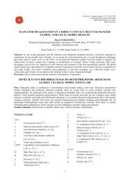
Exp.valveCondenserEvaporatorComp.Three-waymix<strong>in</strong>g valveManometerTCBDAIce tankRotometerCirculationpumpGlycolwatertankWaterTest <strong>tube</strong>Figure 1. Schematic view of experimental test rigThe coils were placed <strong>in</strong>to a circular polyethylene tankhav<strong>in</strong>g a diameter of 1 m and an overall height of 1.5 m.Charg<strong>in</strong>g and discharg<strong>in</strong>g tests were carried out todeterm<strong>in</strong>e the performance of the system constructed.The experiments of Fertelli et al. (2006 and 2008)showed that mechanisms observed dur<strong>in</strong>g the <strong>ice</strong><strong>formation</strong> (supercool<strong>in</strong>g, nucleation, and dendritic <strong>ice</strong><strong>formation</strong>) are very important parameters for systemperformance and they should be <strong>in</strong>vestigated <strong>in</strong> detail.A parallel experimental system was constructed tounderstand solid-liquid phase change heat transferphenomena <strong>around</strong> a <strong>tube</strong>.In this study, phase change phenomena <strong>around</strong> a<strong>horizontal</strong> <strong>tube</strong> were <strong>in</strong>vestigated both experimentallyand analytically. An experimental <strong>in</strong>vestigation wascarried at three different heat transfer fluid <strong>in</strong>lettemperatures <strong>in</strong> order to study the dynamic behavior of<strong>ice</strong> layer <strong>formation</strong> on <strong>tube</strong>. A mathematical model wasalso developed the heat transfer process for phasechange phenomenon <strong>around</strong> a <strong>horizontal</strong> <strong>tube</strong>.EXPERIMENTAL SYSTEMAs seen <strong>in</strong> Figure 1, experimental unit consists of a test<strong>tube</strong> for <strong>ice</strong> <strong>formation</strong>, an air-cooled water chiller unit, apump, pip<strong>in</strong>g, control valves and measurement system.To simulate the conditions <strong>in</strong> <strong>ice</strong>-on-coil type <strong>ice</strong>storage tank, the test <strong>tube</strong> is made of polyethylene pipewith 16 mm outside diameter, 2 mm thickness and 4 mlong. It was placed <strong>in</strong>side a <strong>rectangular</strong> <strong>vessel</strong> of 64 mmwide, 75 mm high and 4000 mm long. The <strong>vessel</strong> wasbuilt from transparent acryclic plates of 4 mm thick, tobe able to take photographs of solidification process<strong>around</strong> the <strong>tube</strong>. The <strong>vessel</strong> was filled with tap water toa depth of 50 mm and <strong>in</strong>sulated from all sides <strong>in</strong>clud<strong>in</strong>gits cover, by 5 cm thick elastomeric rubber foam layerto reduce the heat transfer through the walls.Ethylene glycol-water solution was used as the heattransfer fluid. It is cooled <strong>in</strong> the evaporator of the aircooledwater chiller unit and pumped to the test sectionpass<strong>in</strong>g through a valve, which is used for flow rateadjusment, and a rotameter. Temperature of theethylene glycol-water solution enter<strong>in</strong>g <strong>in</strong>to the testsection was kept constant at the desired level us<strong>in</strong>g acontrol system, which is constituted of motorized twoand three way valves and temperature sensors. Flowrate of the transfer fluid was measured us<strong>in</strong>g arotometer located upstream of the test section. Twothermocouples were used to measure the <strong>in</strong>let and theoutlet temperatures of the heat transfer fluid. Totally 20thermocouples were replaced <strong>in</strong>to water at 7 differentaxial positions (Figure 2) along the test <strong>tube</strong> fordetect<strong>in</strong>g variation of the water temperature <strong>in</strong> the<strong>vessel</strong> One thermocouple was utilized at eachmeasur<strong>in</strong>g station except the first (x/L=0.1), the middle(x/L=0.47) and the last (x/L=0.86) ones. 8thermocouples were used at the first and the laststations, while 4 thermocouples were used at the middleone (Figure 3) to be able to detect the water temperaturevariation at these cross sections <strong>in</strong> detail. Ambient airtemperature was also monitored us<strong>in</strong>g a thermocouple.77
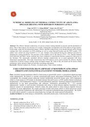
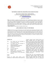
Waterglycolsolution410 mm 500 mm 500 mm 470 mm 580 mm 480 mm 500 mm 560 mmFigure 2. Measurement stations along test <strong>tube</strong>Tw4Tw4Tw3Tw3Tw3Tw6 Tw5Tw2Tw1Tw7 Tw813 10 1 1 10 135 14324275Tw2Tw1143242755Tw6 Tw5Tw2Tw1Tw7 Tw813 10 1 1 10 131 8323975a) x/L= 0.1 b) x/L= 0.47 c) x/L= 0.86Figure 3. Temperature measurement locations with<strong>in</strong> the waterAll the thermocouples used were K type, teflon<strong>in</strong>sulated thermocouples. An <strong>ice</strong>-bath was employed asthe reference junction for all the thermocouples used.Outputs of the thermocouples were monitoredcont<strong>in</strong>uosly with a sampl<strong>in</strong>g rate of 30 read<strong>in</strong>gs/s, us<strong>in</strong>ga computer-controlled data logg<strong>in</strong>g system.Due to the experimental nature of the present work, carewas given to the uncerta<strong>in</strong>ty <strong>in</strong> measurements. The fluidflow rate is measured by means of a calibratedrotometer with accuracy of ± 4%. To performcalibration of the rotometer, water was pumped from asupply reservoir to a constant head reservoir. Fromthere, water flowed to a weigh<strong>in</strong>g tank through themeasur<strong>in</strong>g section with the rotometer under test. Theflow rate was adjusted with a control valve situated atthe downstream end of the test section. The rotometerwas calibrated by measur<strong>in</strong>g the volume of water thatpasses the rotometer dur<strong>in</strong>g a certa<strong>in</strong> measur<strong>in</strong>g time.Table 1. Uncertanity and range for different parametersParameter Range Uncerta<strong>in</strong>ityTube <strong>in</strong>ner radious (mm) 6 ± 0.1 mmTube outer radious (mm) 8 ± 0.1 mmTube length (m) 0 − 4 ± 0.5 cmFlow rate (l/h) 0 − 1000 ± %4Temperature (ºC) -7 to 30 ± 0.3 ºCIce thickness (mm) 0 − 20 ± 0.1 mmHereto the water was collected <strong>in</strong> the weigh<strong>in</strong>g tank,whereby the volume <strong>in</strong>crement was measured andaverage flow rate was computed by divid<strong>in</strong>g the volumeby the time. Temperatures of water and transfer fluidare measured by means of K type teflon <strong>in</strong>sulatedthermocouples with accuracy ± 0.3 ºC. Thethermocouples were calibrated aga<strong>in</strong>st a plat<strong>in</strong>umresistance thermometer <strong>in</strong> a stirred liquid bath whosetemperature was adjusted with the help of atemperature-measur<strong>in</strong>g bench. Thickness of the <strong>ice</strong>formed <strong>around</strong> the <strong>tube</strong> is measured with ± 0.1 mm.Table 1 shows the range and uncerta<strong>in</strong>ity of parametersfor the experiments. Thickness of the <strong>ice</strong> formed on the<strong>tube</strong> was determ<strong>in</strong>ed us<strong>in</strong>g a visual technique. Icethickness was measured at the same stations wheretemperature measurements were made. Smallobservation w<strong>in</strong>dows are opened through the <strong>in</strong>sulationmaterial at the measur<strong>in</strong>g stations to be able to make <strong>ice</strong>thickness measurements. Photographs of the <strong>ice</strong> weretaken with a digital camera (Nikon Coolpix 8700, 8MP,10x optic zoom) from the front and the top of the<strong>vessel</strong> at each station to be able to detect circumferentialchanges <strong>in</strong> <strong>ice</strong> thickness. Different light sources andpositions were tested dur<strong>in</strong>g the prelimenary experimetsto determ<strong>in</strong>e the best light<strong>in</strong>g arrangement. A travers<strong>in</strong>gmechanism was designed to be able to detect the <strong>ice</strong><strong>formation</strong> along the <strong>tube</strong> with a short period of timebetween the stations. The time period between any twomeasur<strong>in</strong>g station was 20 s at maximum. Allphotographs were taken <strong>in</strong> close-up mode with 5 MPresolution. Figure 4 shows two images of solidificationtaken at two different times at the first measur<strong>in</strong>gstation (x/L=0.1) for an <strong>in</strong>let temperature of -5.8 ºC,flow rate 900 l/h as an example to the images takendur<strong>in</strong>g the experimets. At the end of experiments, thephotographs taken were transferred to an image analysisprogram (Image-ProPlus 4.5) for post process<strong>in</strong>g. Us<strong>in</strong>gsome of the techniques offerred by the program, brightimages that clearly <strong>in</strong>dicate the boundaries of the <strong>ice</strong>formed <strong>around</strong> the <strong>tube</strong> were obta<strong>in</strong>ed. From the imagesprocessed, thickness of the <strong>ice</strong> was determ<strong>in</strong>ed for thetop and bottom of the pipe separately (left and rightsides of the pipe for the photographs taken from the topof the pipe) us<strong>in</strong>g the pipe diameter as a referencedimension.78
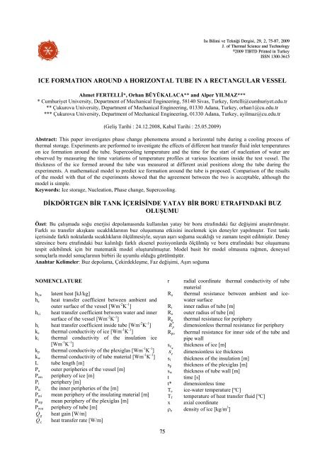
(a)(b)Figure 4. Photographs of the <strong>ice</strong> formed <strong>around</strong> test <strong>tube</strong> at two different times (a:3000, b:11900 s)MATHEMATICAL MODELResults of the experiments carried out revealed that,temperature of the heat transfer fluid flow<strong>in</strong>g throughthe <strong>tube</strong> (T f ) does not change too much between the<strong>tube</strong> <strong>in</strong>let and exit. Therefore, it can be assumedconstant (Figure 5). Because <strong>tube</strong> wall is th<strong>in</strong> andthermal conductivity is not high, the heat transferbetween <strong>ice</strong>-water surface and fluid flow<strong>in</strong>g <strong>in</strong> the <strong>tube</strong>can be assumed as one-dimensional.Figure 5. Schematic of <strong>ice</strong> <strong>formation</strong> processAt an axial position of the <strong>tube</strong>, the amount of heattransferred per length of the <strong>tube</strong> (calculated from;.QTeFlowxTPhase Change Material (Water)Te−T=RpfIceRi Ro rQ .x) can be(1)where T e is the temperature of the <strong>ice</strong> and R p is thermalresistance based on the peripheries, <strong>in</strong>stead of thesurface areas:seswr RoRiR .wp +hiPikwP+wm= 1sesek Pem(2)<strong>in</strong> which k w and k e are the thermal conductivities of the<strong>tube</strong> material and <strong>ice</strong>, respectively. h i is the convectiveheat transfer coefficient <strong>in</strong>side the <strong>tube</strong>. The peripheries(P i , P wm and P em ) are obta<strong>in</strong>ed from the follow<strong>in</strong>gequations:P = 2 π(3)iR i( R R )o iwm= π (4)RoPPem2 −lnR2 π se=⎛ Ro+ sln⎜⎝ RoDef<strong>in</strong><strong>in</strong>gR +ies⎞⎟⎠(5)wpo= 1 (6)hiPikwPwmr = R o+ s e(7)andR * = R / R(8)Rp*poppo= 2 π k R R(9)R oepoor * = r /(10)the follow<strong>in</strong>g equation is obta<strong>in</strong>ed from eq. (2):79
** ln rRp= 1+(11)R*poSimilar to the heat transfer from <strong>ice</strong>-water surface toflow<strong>in</strong>g fluid <strong>in</strong> the <strong>tube</strong>, heat is also transferred fromambient to the <strong>ice</strong>-water surface. The heat ga<strong>in</strong> ( Q & g)per length of the <strong>tube</strong> can be written as:TaTeQ& −g=(12)RaHere T a and R a are ambient temperature and thermalresistance based on periphery between ambient and <strong>ice</strong>watersurface, respectively. The outer surface of the<strong>vessel</strong> is <strong>in</strong>sulated to m<strong>in</strong>imize heat ga<strong>in</strong> ( Q & g) from theambient. R a can be calculated from:Rss1ipa= + + +(13)kiPmikpPmphciPichaPawhere h a is the heat transfer coeff<strong>ice</strong>nt between ambientand outer surface of the <strong>vessel</strong> and h ci is heat transfercoefficient between water <strong>in</strong> the <strong>vessel</strong> and <strong>in</strong>nersurface of the <strong>vessel</strong>. s p and k p are the thickness andthermal conductivity of the plexiglas, respectively. P mpis the mean periphery of the plexiglas. P ic and P a are the<strong>in</strong>ner and outer peripheries of the <strong>vessel</strong>, respectively. s iand k i are the thickness and thermal conductivity of the<strong>in</strong>sulation. P mi is the mean periphery of the <strong>in</strong>sulat<strong>in</strong>gmaterial. The difference between1Q & xandQ & gis usedfor <strong>ice</strong> production, because the temperature differencebetween fluid (T f ) and <strong>ice</strong>-water surface temperature(T e ) is so low that sensible heat storage of <strong>ice</strong> can beneglected compared with the latent heat of freez<strong>in</strong>g.Therefore, one can write the follow<strong>in</strong>g equation;( Q − Q & ) dt = ρ h 2 π r dr& (14)xgeewwhere ρeis the density of the <strong>ice</strong>, h ew is the latent heatof freez<strong>in</strong>g of water and t is the time. Us<strong>in</strong>g eqs. (1),(12) and (14), the follow<strong>in</strong>g equation is obta<strong>in</strong>ed:2 π hewr drdt =Te−TfTa−T−R RpUtiliz<strong>in</strong>g the follow<strong>in</strong>g def<strong>in</strong>itions,*e ft t22 π ρehewRoaepo(15)T −T= (16)R* RaRa=RpoTe−TfT −Tae(17)the follow<strong>in</strong>g dimensionless differential equation (18) isfound:dt*R r dr= (18)* * *p* *1−Rp/ RaBecause of the <strong>in</strong>sulation,compared withas:R * ashould be very big*Rp. Therefore eq. (18) can be rewritten⎛dt⎟ ⎟ ⎞⎝ ⎠Insert<strong>in</strong>g eq. (11) <strong>in</strong>to eq. (18) yields:*R2* * p * *=⎜Rp+ r dr(19)⎜*Ra* 2( r )⎤* *⎡* 1 1 ⎛ 2 ⎞* lndt = ⎢1 + 1 ln rr dr* + ⎜ ⎟*** * 2⎢ RaR+ +poRa RaR ⎥ ⎥ (20)⎣⎝ ⎠po ⎦With the <strong>in</strong>tegration of this equation with the boundarycondition,t * = 0 : r * = 1(21)the follow<strong>in</strong>g equation is obta<strong>in</strong>ed:* 2( ln r )*12*12*⎛ ⎞ ⎛ ⎞1 ⎜ r − ⎟ rt = ⎜ ⎟+*+2*⎝ R ⎜ ⎟a ⎠ ⎝ ⎠ 2 RaR⎡ * 2 ⎛ * 1 ⎞ 1 ⎤⎢r⎜ln− ⎟ + ⎥⎣ ⎝r 2 ⎠ 2⎦* 2po1 +2 R*po⎡⎛ 2 ⎞ 1⎢⎜1⎟+ −**⎢⎣⎝ Ra⎠ RaRIce thickness s e can be made dimensionless witheeo*po(22)s * = s / R(23)Therefore, the follow<strong>in</strong>g equation can be written us<strong>in</strong>geq. (10):* *r 1+ se= (24)RESULT AND DISCUSSIONSExperimental ResultsExperiments were carried out at a fixed transportmedium flow rate of 900 l/h (corresponds to a Reynoldsnumber of 5318 at the <strong>tube</strong> <strong>in</strong>let) and three different<strong>in</strong>let temperatures (-4.3 ºC, -4.9 ºC and -5.8 ºC). Thetemperature of the water <strong>in</strong>side the <strong>vessel</strong> was keptbetween 0 ºC and 1 ºC at the beg<strong>in</strong>n<strong>in</strong>g of theexperiments to m<strong>in</strong>imize the natural convection effects.As an example to the water temperature measurements,Figure 6 shows time wise variations of the watertemperatures at the measurement po<strong>in</strong>ts <strong>in</strong>side the<strong>vessel</strong> for a transfer fluid <strong>in</strong>let temperature of -5.8 ºC.Sensible heat is extracted from the water <strong>in</strong>side the<strong>vessel</strong> and transferred to the transfer medium.⎤⎥⎥⎦80
Temperature ( o C)Temperature ( o C)Temperature ( o C)1,510,50-0,5-1-1,5-2-2,51,510,50-0,5-1-1,5-2-2,51,510,50-0,5-1-1,5-2-2,5-3(a)45 637 80 1000 2000 3000 4000 5000 6000 7000 8000 9000 10000 11000 12000 13000Time (s)(b)0 1000 2000 3000 4000 5000 6000 7000 8000 9000 10000 11000 12000 13000Time (s)(c)0 1000 2000 3000 4000 5000 6000 7000 8000 9000 10000 11000 12000 13000Time (s)21432145 637 821T1 T2 T3 T4 T5 T6 T7 T8Figure 6. Variation of water temperature with time at three measurement stations for T <strong>in</strong> = -5.8 ºC (a: x/L = 0.1, b: x/L = 0.47,c: x/L = 0.86)81
10,50x/L=0.10 x/L=0.23 x/L=0.35 x/L=0.4781x/L=0.62 x/L=0.74 x/L=0.86Temperature ( o C)-0,5-1-1,5-2-2,5-30 1000 2000 3000 4000 5000 6000 7000 8000 9000 10000 11000 12000 13000Time (s)Figure 7. Variation of water temperature with time at positions just above the test <strong>tube</strong> (thermocouple 3) for different axialmeasurement stations (T <strong>in</strong> = -5.8 ºC)As a result, temperature of the water decreases steadilyat all measurement po<strong>in</strong>ts except at the bottom of the<strong>tube</strong>.The phase change process does not start at theequilibrium freez<strong>in</strong>g po<strong>in</strong>t of water (0 ºC) andtemperature of the water decreases below 0 ºC. Cool<strong>in</strong>gcont<strong>in</strong>ues until the start of nucleation of <strong>ice</strong>. Thisprocess is called as supercool<strong>in</strong>g. Supercooled water is<strong>in</strong> a metastable liquid state. The maximum possiblesupercool<strong>in</strong>g (T max ), which is -38±2 ºC, can be achievedwhen the water is free of any solid particles that cancatalyze <strong>ice</strong> germ <strong>formation</strong> (pure water) (Koop, 2004).At about this temperature, freez<strong>in</strong>g happens as ahomogeneous nucleation. When the temperature ishigher than the limit temperature (T max ), heterogeneousnucleation occurs. In heterogeneous nucleation, <strong>ice</strong>grows from crystals that form <strong>in</strong> the water on freez<strong>in</strong>gnuclei. The <strong>ice</strong> formed dur<strong>in</strong>g this stage is calleddendritic <strong>ice</strong>. The degree of supercool<strong>in</strong>g temperaturedepends on properties of the solid particles <strong>in</strong>side thefluid. A liquid below its freez<strong>in</strong>g po<strong>in</strong>t will crystallize <strong>in</strong>the presence of a seed crystal or nucleus <strong>around</strong> which acrystal structure can form. However, lack<strong>in</strong>g any suchnucleus, the liquid phase can be ma<strong>in</strong>ta<strong>in</strong>ed all the waydown to the temperature at which crystal homogeneousnucleation occurs.As can be seen from Figure 6, supercool<strong>in</strong>g occurs at allmeasurement po<strong>in</strong>ts except the bottom of the <strong>tube</strong> andthe degree of it is between -1.4 ºC and -3 ºC. Oncenucleation occurs, a very th<strong>in</strong> layer of dendritic <strong>ice</strong><strong>formation</strong> starts at the outer surface of the <strong>tube</strong> <strong>in</strong> theentrance region (x/L=0.1), and propagates <strong>in</strong> the axialdirection. When the dendritic <strong>ice</strong> first forms, thetemperature rises rapidly to the freez<strong>in</strong>g temperature asa result of the latent heat of fusion of water .Compared with the supercool<strong>in</strong>g process, duration ofthis process is very short, last<strong>in</strong>g only 1 to 3 s,depend<strong>in</strong>g on the degree of supercool<strong>in</strong>g and theposition.Dendritic <strong>ice</strong> <strong>formation</strong> is followed by latent heatthermal storage process, dur<strong>in</strong>g which a relatively thicklayer of <strong>ice</strong> starts to form <strong>around</strong> the <strong>tube</strong> outer surface.Dur<strong>in</strong>g this period, temperature rema<strong>in</strong>s at freez<strong>in</strong>gpo<strong>in</strong>t temperature (0 ºC) for a certa<strong>in</strong> period of time.However, when the <strong>ice</strong> is formed, temperature of the <strong>ice</strong>beg<strong>in</strong>s to fall below 0 ºC, due to heat transfer from thewater <strong>in</strong>side the <strong>vessel</strong> to the heat transfer fluid (cool<strong>in</strong>gof <strong>ice</strong>). Temperature decrease can be clearly observedwhen the measur<strong>in</strong>g po<strong>in</strong>t (thermocouple) is covered bythe <strong>ice</strong> (thermocouples 2, 3, 6 and 7 <strong>in</strong> Figure 6a).Temperature of the water never decreases down tofreez<strong>in</strong>g temperature (0 ºC) at the bottom of the <strong>vessel</strong>(thermocouples 1 and 2) dur<strong>in</strong>g <strong>ice</strong> <strong>formation</strong>. Theslight temperature <strong>in</strong>crease at the beg<strong>in</strong>n<strong>in</strong>g of theexperiment is due to collection of warm water at thebottom of the <strong>vessel</strong>.The same processes can also be seen from Figure 7 thatshows the variation of water temperature with time nearthe <strong>tube</strong> wall (thermocouple 3) at different axialpositions. S<strong>in</strong>ce the thermocouple 3 is located veryclose to the <strong>tube</strong>, it is covered by the <strong>ice</strong> as soon as <strong>ice</strong><strong>formation</strong> starts. Therefore, temperature stays constantat 0 ºC only for a very short period of time.Variation of the time from the beg<strong>in</strong>n<strong>in</strong>g of theexperiment to the start of nucleation (nucleation time)along the pipe length is given <strong>in</strong> Figure 8 for different<strong>in</strong>let temperatures of heat transfer fluid. As can be seenfrom the figure, nucleation first starts at the entranceregion, which is the coldest region, and propagatesalong the <strong>tube</strong>.82
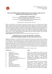
Nucleation time (s)35003000250020001500Tglycol= -5.8 ºCTglycol= -4.9 ºCTglycol= -4.3 ºCIce thickness (mm)141210864TopBottomRightLeft10005000 0,2 0,4 0,6 0,8 1Axial distance (x/L)Figure 8. Variation of nucleation time along <strong>tube</strong> for differenttransfer fluid <strong>in</strong>let temperaturesNucleation time <strong>in</strong>creases almost l<strong>in</strong>early with the axialdistance for all <strong>in</strong>let temperatures. It is obvious thatfluid <strong>in</strong>let temperature seriously affects the onset of thephase change of water and nucleation time. Nucleationtime <strong>in</strong>creases with the <strong>in</strong>crease of transfer fluid <strong>in</strong>lettemperature. Increase of <strong>in</strong>let temperature from -5.8 ºCto -4.3 ºC almost doubles the nucleation time at all axialpositions along the <strong>tube</strong>. Due to high fluid <strong>in</strong>lettemperature, the temperature of water needs more timeto reach the nucleation temperature. Similar results werealso reported by Chen et al. (2000) who conducted aseries of experiments to <strong>in</strong>vestigate the supercool<strong>in</strong>gphenomenon and the effect of <strong>in</strong>let coolant temperatureon the nucleation of water <strong>in</strong>side cyl<strong>in</strong>der.The thickness of the <strong>ice</strong> formed at the bottom, top, rightand left sides of the <strong>tube</strong> was determ<strong>in</strong>ed at differentaxial positions dur<strong>in</strong>g the experiments. As an exampleto the measurements, Figure 9 shows time wisevariations of the <strong>ice</strong> thickness at three axial positions(x/L=0.1, 0.47 and 0.86) for a transfer fluid <strong>in</strong>lettemperature of -5.8 ºC. Photographs of the <strong>ice</strong><strong>formation</strong> from the top of the <strong>tube</strong> were not suitable forthe post process<strong>in</strong>g because of dense dendritic <strong>ice</strong><strong>formation</strong> at the beg<strong>in</strong>n<strong>in</strong>g of the experiments at the topof the <strong>tube</strong>.Similar trends are observed at all measur<strong>in</strong>g stationsalong the <strong>tube</strong>. At the beg<strong>in</strong>n<strong>in</strong>g of the <strong>ice</strong> <strong>formation</strong>,thickness of the <strong>ice</strong> is almost equal <strong>around</strong> the <strong>tube</strong>. Ice<strong>formation</strong> is then better at the upper part of the <strong>tube</strong>than the lower part of the <strong>tube</strong>. This is because of heattransfer from outside, although the <strong>vessel</strong> is <strong>in</strong>sulatedproperly. As result of heat ga<strong>in</strong> from outside, warmwater is collected at the bottom and the cold water iscollected at the top. The difference between the top andthe bottom of the <strong>tube</strong> <strong>in</strong> terms of the <strong>ice</strong> thickness isapproximately constant (0.6 mm) after 3000 s. Thethickness of the <strong>ice</strong> at the right and left sides of the <strong>tube</strong>is close to each other.Ice thickness (mm)Ice thickness (mm)201412108642014121086420(a)0 5000 10000 15000Time (s)TopBottomRightLeft(b)0 5000 10000 15000Time (s)TopBottomRightLeft(c)0 5000 10000 15000Time (s)Figure 9. Variation of <strong>ice</strong> thickness with time for top, bottomand sides of <strong>tube</strong> for T <strong>in</strong> = -5.8 ºC (a: x/L= 0.1, b: x/L= 0.47,c: x/L= 0.86)The shape of the <strong>ice</strong> <strong>formation</strong> dur<strong>in</strong>g the experimentsat three axial positions (x/L=0.1, 0.47 and 0.86) isdepicted <strong>in</strong> Figure 10 for three different transfer fluid<strong>in</strong>let temperatures (-4.3 ºC, -4.9 ºC and -5.8 ºC).83
2010(mm)0-10-2020-10x/L=0.10x/L= 0.47 x/L= 0.860(mm)10 20 -20 -10 0(mm)10 20 -20 -10 0(mm)10 20(a)10(mm)0-10x/L=0.10 x/L= 0.47 x/L= 0.86-20 -10 0 10 20 -20 -10 0 10 20-20-10 0 10 20(mm) (mm) (mm)(b)2010(mm)0-10x/L=0.10 x/L= 0.47 x/L= 0.86-20 -10 0 10 20 -20 -10 0 10 20 -20 -10 0 10 20(mm) (mm) (mm)(c)1920s2880s 4140s 5760s6900s9420s11700sFigure 10. Evolution of <strong>ice</strong>-water <strong>in</strong>terface with time for different transfer fluid <strong>in</strong>let temperatures (a: T <strong>in</strong> = -4.3 °C, b: T <strong>in</strong> = -4.9°C, c: T <strong>in</strong> = -5.8 °C)When the <strong>ice</strong> forms first, it has almost a circular shape.However, the shape is distorted <strong>in</strong> later stages of <strong>ice</strong><strong>formation</strong>. Ice thickness at the top becomes higher thanthe bottom, right and left, and therefore, the shape takesan oval form.Influence of transfer fluid <strong>in</strong>let temperature on <strong>ice</strong>thickness is shown <strong>in</strong> Figure 11 for 3 different timesdur<strong>in</strong>g the experiments (2880 s, 6900 s and 11700 s) at84an axial position of x/L=0.47. With the <strong>in</strong>crease oftransfer fluid <strong>in</strong>let temperature, <strong>ice</strong> thickness decreasesat all po<strong>in</strong>ts <strong>around</strong> the <strong>tube</strong>. The same trend is alsoobserved at other axial positions. As discussed above,<strong>ice</strong> <strong>formation</strong> is almost uniform <strong>around</strong> the <strong>tube</strong> at the<strong>in</strong>itial stages of <strong>ice</strong> <strong>formation</strong> (2880 s). However laterthe uniformity is distorted and a clear differencebetween the top and bottom is observed at 11700 s.
1412Ice thickness (mm)1086420-6 -5,8 -5,6 -5,4 -5,2 -5 -4,8 -4,6 -4,4 -4,2 -4Transfer fluid <strong>in</strong>let temperature ( o C)2880 Top 2880 Bottom 2880 Right 2880 Left6900 Top 6900 Bottom 6900 Right 6900 Left11700 Top 11700 Bottom 11700 Right 11700 LeftFigure 11. Influence of transfer fluid <strong>in</strong>let temperature on <strong>ice</strong> thickness at x/L= 0.47Comparison of Mathematical Model withExperimental ResultsA simple model for the <strong>formation</strong> of <strong>ice</strong> <strong>around</strong> acyl<strong>in</strong>drical <strong>tube</strong> is given above. Comparison of themodel and experimental results are given <strong>in</strong> Figure 12for three different transfer fluid <strong>in</strong>let temperatures (-4.3,-4.9 and -5.8 ºC) which corresponds to R * = 3. 866 ,R * a= 4.566 and R* a= 5. 238 , respectively. The value of*Rpois 1.912 for the experiments. The experimentalvalues shown <strong>in</strong> this figure were obta<strong>in</strong>ed by averag<strong>in</strong>g<strong>ice</strong> thickness values determ<strong>in</strong>ed at top, bottom, right andleft of the <strong>tube</strong> at each axial position. S<strong>in</strong>ce the timescale starts from the <strong>formation</strong> of <strong>ice</strong> <strong>in</strong> the model, theexperimentally obta<strong>in</strong>ed values at different axialpositions were shifted accord<strong>in</strong>g to time at which <strong>ice</strong><strong>formation</strong> starts at the axial position of <strong>in</strong>terest.Therefore, time scale <strong>in</strong> Figure 12 is not the absolutetime scale, rather represents the time passed from thestart of <strong>ice</strong> <strong>formation</strong>. The figure shows theexperimental <strong>ice</strong> thicknesses at all axial positions withshifted time scales.12ExperimentalIce thickness (mm)1086420Model(a)0 5000 10000 15000Time (s)aIce thickness (mm)Ice thickness (mm)1412108642014121086420ExperimentalModel(b)0 5000 10000 15000Time (s)ExperimentalModel(c)0 5000 10000 15000Time (s)Figure 12. Comparison of <strong>ice</strong> thickness obta<strong>in</strong>ed frommeasurements and model for different transfer fluid <strong>in</strong>lettemperatures (a: T <strong>in</strong> = -4.3 °C, b: T <strong>in</strong> = -4.9 °C, c: T <strong>in</strong> = -5.8°C)85
As can be seen from Figure 12, the agreement betweenthe model and the experimental values is good dur<strong>in</strong>gthe <strong>ice</strong> <strong>formation</strong> process for all transfer fluid <strong>in</strong>lettemperatures. The model under predicts slightly <strong>ice</strong>thickness at the beg<strong>in</strong>n<strong>in</strong>g of the process and overpredicts at the end.CONCLUSIONIn the present study, phase change phenomena and theeffect of heat transfer fluid temperature on <strong>ice</strong> <strong>formation</strong><strong>around</strong> a <strong>horizontal</strong> <strong>tube</strong> <strong>in</strong> a <strong>rectangular</strong> <strong>vessel</strong> were<strong>in</strong>vestigated both experimentally and analytically.Based on the obta<strong>in</strong>ed results our conclusions aresummarized as follows:1. Experimental results show that supercool<strong>in</strong>g occursat all axial measur<strong>in</strong>g stations along the <strong>tube</strong> andnucleation first starts at the entrance region andpropagates along the <strong>tube</strong>. Nucleation temperaturesfor all measurement po<strong>in</strong>ts are between -1.4 ºC and-3 ºC.2. It is obvious that the heat transfer fluid <strong>in</strong>lettemperature seriously affects the onset of the phasechange of water and nucleation time. With thedecrease of heat transfer fluid <strong>in</strong>let temperature,nucleation time decreases. Furthermore nucleationtime <strong>in</strong>creases with the axial distance for all heattransfer fluid <strong>in</strong>let temperatures.3. The thickness of the <strong>ice</strong> formed at the top andbottom sides of <strong>tube</strong> is different from each other,although the thickness of the <strong>ice</strong> formed at the rightand left sides is close to each other. Ice thickness<strong>around</strong> <strong>tube</strong> is substantially <strong>in</strong>fluenced by naturalconvection that occurs with<strong>in</strong> the water. With the<strong>in</strong>crease of transfer fluid <strong>in</strong>let temperature, <strong>ice</strong>thickness decreases at all po<strong>in</strong>ts <strong>around</strong> the <strong>tube</strong>.4. Ice thickness evaluated by mathematical modelagrees reasonably with the experimental data for alltransfer fluid <strong>in</strong>let temperatures.REFERENCESBüyükalaca O., Yılmaz T., Fertelli A., Ice Storage Air-Condition<strong>in</strong>g System, Proceed<strong>in</strong>gs of the EasternMediterranean and Southeastern Anatolia RegionMach<strong>in</strong>e and System Design-Production Congress (<strong>in</strong>Turkish), 95-101, Turkey, 2003.Chen S.L., Chen C.L., Th<strong>in</strong> C.C., Lee T.S., Ke M.C.,An Experimental Investigation of Cold Storage <strong>in</strong> anEncapsulated Thermal Storage Tank, ExperimentalThermal and Fluid Science 23, 133-144, 2000.Cheng K.C., Inaba H., Gilp<strong>in</strong> R.R., Effects of NaturalConvection on Ice Formation <strong>around</strong> an IsothermallyCooled Horizontal Cyl<strong>in</strong>der, Journal of Heat Transfer110, 931-937, 1988.D<strong>in</strong>cer I., On Thermal Energy Storage Systems andApplications <strong>in</strong> Build<strong>in</strong>gs, Energy and Build<strong>in</strong>gs 34,377-388, 2002.Dorgan C.E., Elleson J.S., Design Guide for CoolThermal Storage, American Society of Heat<strong>in</strong>gRefrigeration and Air-Condition<strong>in</strong>g Eng<strong>in</strong>eer<strong>in</strong>g,Atlanta, 1993.Erek A., Ilken Z., Acar M.A., Experimental andNumerical Investigation of Thermal Energy Storagewith a F<strong>in</strong>ned Tube, International Journal of EnergyResearch 29, 283–301, 2005.Fertelli A., Büyükalaca O., Yılmaz T., Performance ofan Ice Storage Air-Condition<strong>in</strong>g System, Proceed<strong>in</strong>gsof the Fifth GAP Eng<strong>in</strong>eer<strong>in</strong>g Congress (<strong>in</strong> Turkish),273-280, Turkey, 2006.Fertelli A., Air-condition<strong>in</strong>g System with Ice ThermalEnergy Storage, Ph.D Thesis, Institute of natural andapplied sciences of Çukurova University, Adana, 2008.Fukusako S., Yamada M., Recent Advances <strong>in</strong> Researchon Water-Freez<strong>in</strong>g and Ice-Melt<strong>in</strong>g Problems, Exp.Thermal and Fluid Science 6, 90-105, 1993.Habeebullah B.A., An Experimental Study on IceFormation <strong>around</strong> Horizontal Long Tubes, InternationalJournal of Refrigeration 30 (5), 789-797, 2007.Hasna<strong>in</strong> S.M., Review on Susta<strong>in</strong>able Thermal EnergyStorage Techologies, Part:II Cool Thermal Storage,Energy Conversion &Management 39 (11), 1139-1153,1998.Hirata T., Matsui H., Ice Formation and Heat Transferwith Water Flow <strong>around</strong> Isothermally Cooled Cyl<strong>in</strong>dersArranged <strong>in</strong> a L<strong>in</strong>e, Journal of Heat Transfer 112, 707-713, 1990.Intemann P.A., Kazmierczak M., Heat Transfer and IceFormations Deposited upon Cold Tube BundlesImmersed <strong>in</strong> Flow<strong>in</strong>g Water - I. Convective analysis,Int. J. Heat Mass Transfer 40 (3), 557-572, 1997.Intemann P.A., Kazmierczak M., Heat Transfer and IceFormations Deposited upon Cold Tube BundlesImmersed <strong>in</strong> Flow<strong>in</strong>g Water - II. Conjugate analysis,Int. J. Heat Mass Transfer 40 (3), 573-588, 1997.K.A.R I., Henriquuez , Moura L.F.M., Ganzarolli M.M.,Ice Formation <strong>around</strong> Isothermal Radial F<strong>in</strong>ned Tubes,Energy Conversion & Management 41, 585–605, 2000.Kayansayan N., Acar M.A., Ice Formation <strong>around</strong> aF<strong>in</strong>ned-Tube Heat Exchanger for Cold Thermal EnergyStorage, International Journal of Thermal Sciences 45,405-418, 2006.86
Koop T., Homogeneous Ice Nucleation <strong>in</strong> Water andAqueous Solutions, Z. Phys. Chem. 218 (11), 1231-1258, 2004.Milon J.J., Braga S.L., Supercool<strong>in</strong>g Water <strong>in</strong>Cyl<strong>in</strong>drical Capsules, 15. Symposium on themophysicalproperties, Boulder, Colorado, U.S.A., 2003.Sasaguchi K., Kusano K., Viskanta R., A NumericalAnalysis of Solid Liquid Phase Change Heat Transfer<strong>around</strong> a S<strong>in</strong>gle and Two Horizontal, Vertically SpacedCyl<strong>in</strong>ders <strong>in</strong> a Rectangular Cavity, Int. J. Heat MassTransfer 40 (6), 1343-1354, 1997.Sasaguchi K., Kusano K., Kitagawa H., Effect ofDensity Inversion on Cool<strong>in</strong>g of Water <strong>around</strong> aCyl<strong>in</strong>der <strong>in</strong> a Rectangular Cavity, Numerical HeatTransferPart A 32, 131-148, 1997.Sparrow E.M., Bahrami P.A., Experiments on NaturalConvection Heat Transfer on the F<strong>in</strong>s of a F<strong>in</strong>nedHorizontal Tube, International Journal of Heat andMass Transfer 23, 1555-1560, 1980.Sparrow E.M., Hsu C.F., Analysis of Two-DimensionalFreez<strong>in</strong>g on the Outside of a Coolant-Carry<strong>in</strong>g Tube,International Journal of Heat and Mass Transfer 24(8), 1345-1357, 1981.Sparrow E.M., Broadbent J.A., Freez<strong>in</strong>g <strong>in</strong> a VerticalTube, Journal of Heat Transfer 105 (2), 217-225, 1983.Stampa C.S., Nieckele A.O., Numerical Study of IceLayer Growth <strong>around</strong> a Vertical Tube, ThermalEng<strong>in</strong>er<strong>in</strong>g 4 (2), 138-144, 2005.Ahmet FERTELLI was born <strong>in</strong> Sivas-Turkey <strong>in</strong> 1975. He graduated from the departmentof mechanical eng<strong>in</strong>eer<strong>in</strong>g at Çukurova University <strong>in</strong> 1998. He obta<strong>in</strong>ed his MSc degreeat Cumhuriyet University <strong>in</strong> 2001. He pursued his PhD studies at Çukurova Universityand received PhD degree <strong>in</strong> 2008. He has been work<strong>in</strong>g as a research assistant atCumhuriyet University s<strong>in</strong>ce 1999. His ma<strong>in</strong> research fields are cool thermal energystorage systems and phase change. He is a member of TTMD and MMO.Orhan BÜYÜKAALACA was born <strong>in</strong> Kaş-Turkey <strong>in</strong> 1964. He graduated from theMechanical Eng<strong>in</strong>eer<strong>in</strong>g Department of Çukurova University <strong>in</strong> 1984. In 1987, heobta<strong>in</strong>ed his MSc degree from the same <strong>in</strong>stitution. He pursued his PhD studies atManchester University and received PhD degree <strong>in</strong> 1993. He worked as AssisstantProfessor and Associate Professor between 1994 and 2003 <strong>in</strong> Çukurova University. Heworked as a visit<strong>in</strong>g researcher at Manchester University <strong>in</strong> 1993 and 1996. He wasappo<strong>in</strong>ted as a Professor <strong>in</strong> the Mechanical Eng<strong>in</strong>eer<strong>in</strong>g Department of ÇukurovaUniversity <strong>in</strong> 2003. He has been the Rector of Osmaniye Korkut Ata University s<strong>in</strong>ce2008. His ma<strong>in</strong> research fields are analysis of meteorological data for heat<strong>in</strong>g and aircondition<strong>in</strong>gsystems, energy analysis, heat pumps and turbulent convective heat transfer.He is a member of TTMD and MMO.Alper YILMAZ was born <strong>in</strong> Tarsus-Turkey <strong>in</strong> 1975. He graduated from the department ofMechanical Eng<strong>in</strong>eer<strong>in</strong>g Department of Boğaziçi University <strong>in</strong> 1997. He pursued his MScand PhD studies at Çukurova University and got his degrees <strong>in</strong> 1999 and 2004,respectively. He was assigned assistant professor of mechanical eng<strong>in</strong>eer<strong>in</strong>g <strong>in</strong> 2006 ands<strong>in</strong>ce then he has been work<strong>in</strong>g at the same <strong>in</strong>stitution. In 2000, he was visit<strong>in</strong>g researcher<strong>in</strong> Berl<strong>in</strong>-Germany by DAAD award. His ma<strong>in</strong> research <strong>in</strong>terests are conductive andconvective heat transfer. He is a member of TTMD and MMO.87