modelling of an automotive air conditioning system using anfis
modelling of an automotive air conditioning system using anfis
modelling of an automotive air conditioning system using anfis

Create successful ePaper yourself
Turn your PDF publications into a flip-book with our unique Google optimized e-Paper software.
Isı Bilimi ve Tekniği Dergisi, 33, 1, 127-137, 2013<br />
J. <strong>of</strong> Thermal Science <strong>an</strong>d Technology<br />
©2013 TIBTD Printed in Turkey<br />
ISSN 1300-3615<br />
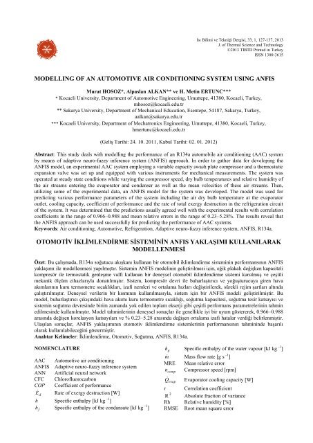
MODELLING OF AN AUTOMOTIVE AIR CONDITIONING SYSTEM USING ANFIS<br />
Murat HOSOZ*, Alpasl<strong>an</strong> ALKAN** ve H. Metin ERTUNC***<br />
* Kocaeli University, Department <strong>of</strong> Automotive Engineering, Umuttepe, 41380, Kocaeli, Turkey,<br />
mhosoz@kocaeli.edu.tr<br />
** Sakarya University, Department <strong>of</strong> Mech<strong>an</strong>ical Education, Esentepe, 54187, Sakarya, Turkey,<br />
aalk<strong>an</strong>@sakarya.edu.tr<br />
*** Kocaeli University, Department <strong>of</strong> Mechatronics Engineering, Umuttepe, 41380, Kocaeli, Turkey,<br />
hmertunc@kocaeli.edu.tr<br />
(Geliş Tarihi: 24. 10. 2011, Kabul Tarihi: 02. 01. 2012)<br />
Abstract: This study deals with <strong>modelling</strong> the perform<strong>an</strong>ce <strong>of</strong> <strong>an</strong> R134a automobile <strong>air</strong> <strong>conditioning</strong> (AAC) <strong>system</strong><br />
by me<strong>an</strong>s <strong>of</strong> adaptive neuro-fuzzy inference <strong>system</strong> (ANFIS) approach. In order to gather data for developing the<br />
ANFIS model, <strong>an</strong> experimental AAC <strong>system</strong> employing a variable capacity swash plate compressor <strong>an</strong>d a thermostatic<br />
exp<strong>an</strong>sion valve was set up <strong>an</strong>d equipped with various instruments for mech<strong>an</strong>ical measurements. The <strong>system</strong> was<br />
operated at steady state conditions while varying the compressor speed, dry bulb temperatures <strong>an</strong>d relative humidity <strong>of</strong><br />
the <strong>air</strong> streams entering the evaporator <strong>an</strong>d condenser as well as the me<strong>an</strong> velocities <strong>of</strong> these <strong>air</strong> streams. Then,<br />
utilizing some <strong>of</strong> the experimental data, <strong>an</strong> ANFIS model for the <strong>system</strong> was developed. The model was used for<br />
predicting various perform<strong>an</strong>ce parameters <strong>of</strong> the <strong>system</strong> including the <strong>air</strong> dry bulb temperature at the evaporator<br />
outlet, cooling capacity, coefficient <strong>of</strong> perform<strong>an</strong>ce <strong>an</strong>d the rate <strong>of</strong> total exergy destruction in the refrigeration circuit<br />
<strong>of</strong> the <strong>system</strong>. It was determined that the predictions usually agreed well with the experimental results with correlation<br />
coefficients in the r<strong>an</strong>ge <strong>of</strong> 0.966–0.988 <strong>an</strong>d me<strong>an</strong> relative errors in the r<strong>an</strong>ge <strong>of</strong> 0.23–5.28%. The results reveal that<br />
the ANFIS approach c<strong>an</strong> be used successfully for predicting the perform<strong>an</strong>ce <strong>of</strong> AAC <strong>system</strong>s.<br />
Keywords: Air <strong>conditioning</strong>, Automotive, Refrigeration, Adaptive neuro-fuzzy inference <strong>system</strong>, ANFIS, R134a.<br />
OTOMOTİV İKLİMLENDİRME SİSTEMİNİN ANFIS YAKLAŞIMI KULLANILARAK<br />
MODELLENMESİ<br />
Özet: Bu çalışmada, R134a soğutucu akışk<strong>an</strong>ı kull<strong>an</strong><strong>an</strong> bir otomobil iklimlendirme sisteminin perform<strong>an</strong>sının ANFIS<br />
yaklaşımı ile modellenmesi yapılmıştır. Sistemin ANFIS modelinin geliştirilmesi için, eğik plakalı değişken kapasiteli<br />
kompresör ile termostatik genleşme valfi kull<strong>an</strong><strong>an</strong> bir deneysel otomobil iklimlendirme sistemi kurulmuş ve çeşitli<br />
mek<strong>an</strong>ik ölçüm cihazlarıyla donatılmıştır. Sistem, kompresör devri ile buharlaştırıcı ve yoğuşturucuya giren hava<br />
akımlarının kuru termometre sıcaklıkları, izafi nemleri ve ortalama hızları değiştirilerek, sürekli rejim şartları altında<br />
çalıştırılmıştır. Deneysel verilerin bir kısmının kull<strong>an</strong>ılmasıyla, sistem için bir ANFIS modeli geliştirilmiştir. Bu<br />
model, buharlaştırıcı çıkışındaki hava akımı kuru termometre sıcaklığı, soğutma kapasitesi, soğutma tesir katsayısı ve<br />
sistemin soğutma devresinde birim zam<strong>an</strong>da yok edilen toplam ekserji gibi çeşitli perform<strong>an</strong>s parametrelerinin tahmin<br />
edilmesinde kull<strong>an</strong>ılmıştır. Model tahminlerinin deneysel sonuçlar ile genellikle iyi bir uyum göstererek, 0.966–0.988<br />
arasında değişen korelasyon katsayıları ve % 0.23–5.28 arasında değişen ortalama izafi hatalar verdiği belirlenmiştir.<br />
Ulaşıl<strong>an</strong> sonuçlar, ANFIS yaklaşımının otomotiv iklimlendirme sistemlerinin perform<strong>an</strong>sının tahmininde başarılı<br />
olarak kull<strong>an</strong>ılabileceğini göstermiştir.<br />
Anahtar Kelimeler: İklimlendirme, Otomotiv, Soğutma, ANFIS, R134a.<br />
NOMENCLATURE<br />
AAC Automotive <strong>air</strong> <strong>conditioning</strong><br />
ANFIS Adaptive neuro-fuzzy inference <strong>system</strong><br />
ANN Artificial neural network<br />
CFC Chlor<strong>of</strong>luorocarbon<br />
COP Coefficient <strong>of</strong> perform<strong>an</strong>ce<br />
E d Rate <strong>of</strong> exergy destruction [W]<br />
h Specific enthalpy [kJ kg –1 ]<br />
h Specific enthalpy <strong>of</strong> the cond<strong>an</strong>sate [kJ kg –1 ]<br />
f<br />
h g Specific enthalpy <strong>of</strong> the water vapour [kJ kg –1 ]<br />
m Mass flow rate [g s –1 ]<br />
MRE Me<strong>an</strong> relative error<br />
n Compressor speed [rpm]<br />
comp<br />
Q evap Evaporator cooling capacity [W]<br />
r Correlation coefficient<br />
2<br />
R Absolute fraction <strong>of</strong> vari<strong>an</strong>ce<br />
Rh Relative humidity [%]<br />
RMSE Root me<strong>an</strong> square error
s Specific entropy [kJ kg –1 K –1 ]<br />
T Temperature [K]<br />
T 0 Ambient temperature [K]<br />
TXV Thermostatic exp<strong>an</strong>sion valve<br />
V Me<strong>an</strong> <strong>air</strong> velocity [m s –1 ]<br />
m<br />
W comp Compressor power [W]<br />
Greek Symbols<br />
Relative humidity [%]<br />
Specific humidity<br />
Subscripts<br />
a Air<br />
A...F Points in the <strong>air</strong> lines as shown in Figure 1<br />
ai Air inlet<br />
ao Air outlet<br />
comp Compressor<br />
cond Condenser<br />
dis Compressor discharge<br />
evap Evaporator<br />
r Refriger<strong>an</strong>t<br />
tot Total<br />
valve Exp<strong>an</strong>sion valve<br />
INTRODUCTION<br />
Automotive <strong>air</strong> <strong>conditioning</strong> (AAC) <strong>system</strong>s have been<br />
adv<strong>an</strong>ced considerably to provide better thermal comfort<br />
<strong>an</strong>d improved fuel economy along with minimum impact<br />
to the environment since General Motors <strong>an</strong>d Packard<br />
Motor Car comp<strong>an</strong>ies developed early AAC <strong>system</strong>s<br />
based on vapour compression refrigeration in 1930s<br />
(Bhatti, 1999a). Although AAC <strong>system</strong>s once used R12<br />
as a st<strong>an</strong>dard refriger<strong>an</strong>t, beginning in 1992, car<br />
m<strong>an</strong>ufacturers started to use R134a as a result <strong>of</strong><br />
Montreal Protocol, which called for a phase out <strong>of</strong> CFC<br />
compounds including R12. On the other h<strong>an</strong>d, triggered<br />
by the regulations <strong>of</strong> the Europe<strong>an</strong> Union that require all<br />
new vehicles receiving type approval in 2011 or later to<br />
use a refriger<strong>an</strong>t with a Global Warming Potential below<br />
150, <strong>automotive</strong> industry is now performing research to<br />
use natural refriger<strong>an</strong>ts such as CO 2 to substitute for<br />
R134a in AAC <strong>system</strong>s.<br />
AAC <strong>system</strong>s are different from domestic <strong>air</strong><br />
<strong>conditioning</strong> <strong>system</strong>s in a few ways. Because the<br />
compressor <strong>of</strong> <strong>an</strong> AAC <strong>system</strong> is driven by the engine,<br />
the compressor speed as well as the cooling capacity <strong>of</strong><br />
the <strong>system</strong> ch<strong>an</strong>ges as a function <strong>of</strong> the engine speeds.<br />
On the other h<strong>an</strong>d, the passenger compartment <strong>of</strong> a<br />
vehicle c<strong>an</strong> be exposed to varying climatic conditions,<br />
which ch<strong>an</strong>ges the <strong>air</strong> <strong>conditioning</strong> load continually.<br />
Consequently, these challenges make AAC <strong>system</strong>s<br />
difficult to model <strong>using</strong> classical techniques <strong>an</strong>d<br />
necessitate experimental studies.<br />
The literature contains limited number <strong>of</strong> research<br />
studies on AAC technology due to its competitive<br />
nature. In response to the Montreal Protocol, some<br />
studies were evaluated the perform<strong>an</strong>ce <strong>of</strong> AAC <strong>system</strong>s<br />
with refriger<strong>an</strong>ts alternative to R12. Jung et al. (1999)<br />
presented experimental perform<strong>an</strong>ce <strong>of</strong><br />
supplementary/retr<strong>of</strong>it refriger<strong>an</strong>t mixtures for R12 used<br />
in existing AAC <strong>system</strong>s. Al-Rabghi <strong>an</strong>d Niyaz (2002)<br />
found that the AAC <strong>system</strong> with R12 yields a higher<br />
coefficient <strong>of</strong> perform<strong>an</strong>ce (COP) by 23% th<strong>an</strong> the<br />
<strong>system</strong> with R134a. Joudi et al. (2003) simulated the<br />
perform<strong>an</strong>ce <strong>of</strong> <strong>an</strong> ideal AAC <strong>system</strong> with R12 <strong>an</strong>d<br />
several alternative refriger<strong>an</strong>ts including some<br />
hydrocarbons. Bhattti (1999b) presented a method for<br />
augmentation <strong>of</strong> AAC <strong>system</strong>s with R134a to lower its<br />
global warming impact. Brown et al. (2002) evaluated<br />
various perform<strong>an</strong>ce parameters <strong>of</strong> AAC <strong>system</strong>s with<br />
CO 2 <strong>an</strong>d R134a, finding that both <strong>system</strong>s <strong>of</strong>fer<br />
comparable perform<strong>an</strong>ce. Liu et al. (2005) investigated<br />
experimental perform<strong>an</strong>ce <strong>of</strong> <strong>an</strong> AAC <strong>system</strong> with CO 2 .<br />
Ghodb<strong>an</strong>e (1999) simulated the perform<strong>an</strong>ce <strong>of</strong> AAC<br />
<strong>system</strong>s <strong>using</strong> several hydrocarbon refriger<strong>an</strong>ts.<br />
Kaynakli <strong>an</strong>d Horuz (2003) investigated experimental<br />
perform<strong>an</strong>ce <strong>of</strong> <strong>an</strong> AAC <strong>system</strong> with R134a to find<br />
optimum operating conditions. Wongwises et al. (2006)<br />
determined experimental perform<strong>an</strong>ce <strong>of</strong> <strong>an</strong> AAC<br />
<strong>system</strong> with several hydrocarbons. Hosoz <strong>an</strong>d Direk<br />
(2006) investigated experimental perform<strong>an</strong>ce <strong>of</strong> <strong>an</strong><br />
R134a AAC <strong>an</strong>d <strong>air</strong>-to-<strong>air</strong> heat pump <strong>system</strong>. Alk<strong>an</strong> <strong>an</strong>d<br />
Hosoz (2010a) compared experimental perform<strong>an</strong>ce<br />
parameters <strong>of</strong> <strong>an</strong> R134a AAC <strong>system</strong> for the cases <strong>of</strong><br />
<strong>using</strong> fixed <strong>an</strong>d variable capacity compressors. They<br />
also presented comparative experimental perform<strong>an</strong>ce <strong>of</strong><br />
<strong>an</strong> R134a AAC <strong>system</strong> for two different types <strong>of</strong><br />
exp<strong>an</strong>sion devices, namely thermostatic exp<strong>an</strong>sion valve<br />
<strong>an</strong>d orifice tube (Alk<strong>an</strong> <strong>an</strong>d Hosoz, 2010b).<br />
In addition to the experimental studies, the<br />
perform<strong>an</strong>ces <strong>of</strong> AAC <strong>system</strong>s were simulated. Lee <strong>an</strong>d<br />
Yoo (2000) developed a simulation model for <strong>an</strong> AAC<br />
<strong>system</strong> by combining the perform<strong>an</strong>ce <strong>an</strong>alysis models<br />
for the components. Jabardo et al. (2002) presented a<br />
steady-state simulation model for <strong>an</strong> AAC <strong>system</strong> <strong>using</strong><br />
a variable capacity compressor, <strong>an</strong>d indicated its validity<br />
on <strong>an</strong> experimental unit. Ti<strong>an</strong> <strong>an</strong>d Li (2005) simulated<br />
steady-state perform<strong>an</strong>ce <strong>of</strong> <strong>an</strong> R134a AAC <strong>system</strong><br />
employing a variable capacity compressor. Hosoz <strong>an</strong>d<br />
Ertunc (2006) developed <strong>an</strong> artificial neural network<br />
model to predict the perform<strong>an</strong>ce <strong>of</strong> <strong>an</strong> AAC <strong>system</strong><br />
with R134a.<br />
It is obvious that mathematical <strong>modelling</strong> <strong>of</strong> AAC<br />
<strong>system</strong>s require a large number <strong>of</strong> geometrical<br />
parameters defining the <strong>system</strong>, which may not be<br />
readily available, <strong>an</strong>d the computer simulations<br />
employed in these models are usually complicated due<br />
to their dealing with the solution <strong>of</strong> complex differential<br />
equations. Furthermore, as mentioned before, ch<strong>an</strong>ging<br />
compressor speed <strong>an</strong>d <strong>air</strong> <strong>conditioning</strong> load make the<br />
<strong>modelling</strong> process more complex. Alternatively, the<br />
operation <strong>of</strong> AAC <strong>system</strong>s c<strong>an</strong> be modelled <strong>using</strong><br />
artificial intelligence techniques such as artificial neural<br />
network (ANN) <strong>an</strong>d adaptive neuro-fuzzy inference<br />
128
<strong>system</strong> (ANFIS) with signific<strong>an</strong>tly less engineering<br />
effort. The main feature <strong>of</strong> these new techniques is the<br />
ability <strong>of</strong> self learning <strong>an</strong>d self-predicting some desired<br />
outputs. These techniques c<strong>an</strong> extract expertise from<br />
data without requiring <strong>an</strong>y explicit mathematical<br />
representation, thus easily <strong>modelling</strong> the physical<br />
phenomena in complex <strong>system</strong>s to predict their<br />
behaviour under given conditions. Therefore, they c<strong>an</strong><br />
be applied to various engineering problems which are<br />
too complex to deal with <strong>using</strong> classical <strong>modelling</strong><br />
techniques.<br />
ANFIS, the less-known approach compared with ANN,<br />
is a s<strong>of</strong>t computing technique that combines the benefits<br />
<strong>of</strong> feed forward calculation <strong>of</strong> output <strong>an</strong>d back<br />
propagation <strong>of</strong> learning capability <strong>of</strong> ANNs <strong>an</strong>d hum<strong>an</strong>like<br />
reasoning style <strong>of</strong> fuzzy logic. Therefore, ANFIS<br />
based models are very powerful universal approximators<br />
with the ability <strong>of</strong> interpretable IF-THEN rules, <strong>an</strong>d they<br />
are applied in m<strong>an</strong>y fields such as <strong>system</strong> identification,<br />
fuzzy control, data processing, etc.<br />
The ANN <strong>modelling</strong> <strong>of</strong> <strong>air</strong> <strong>conditioning</strong> <strong>an</strong>d<br />
refrigeration <strong>system</strong>s has been studied by m<strong>an</strong>y<br />
investigators. However, the application <strong>of</strong> ANFIS<br />
approach to the <strong>modelling</strong> <strong>of</strong> thermal <strong>system</strong>s is a more<br />
recent progress, although ANFIS was first introduced in<br />
early 90s (J<strong>an</strong>g, 1993). Hasiloglu et al. (2004)<br />
performed ANFIS <strong>modelling</strong> <strong>of</strong> the tr<strong>an</strong>sient heat<br />
tr<strong>an</strong>sfer in circular duct flow. Esen et al. (2007)<br />
predicted the perform<strong>an</strong>ce <strong>of</strong> a ground-coupled heat<br />
pump <strong>system</strong> <strong>using</strong> ANFIS. They also compared the<br />
ANFIS predictions with the ANN ones for the groundcoupled<br />
heat pump <strong>system</strong> (Esen et al., 2008). Ertunc<br />
<strong>an</strong>d Hosoz (2008) developed ANFIS <strong>an</strong>d ANN models<br />
for predicting the perform<strong>an</strong>ce <strong>of</strong> <strong>an</strong> evaporative<br />
condenser. They found that the accuracies <strong>of</strong> ANFIS<br />
predictions were slightly better th<strong>an</strong> those <strong>of</strong> ANN ones.<br />
Soyguder <strong>an</strong>d Alli (2009) predicted the f<strong>an</strong> speed for<br />
energy saving in <strong>an</strong> HVAC <strong>system</strong> <strong>using</strong> ANFIS. Das<br />
<strong>an</strong>d Kishor (2009) developed <strong>an</strong> ANFIS model for<br />
predicting the heat tr<strong>an</strong>sfer coefficient in pool boiling <strong>of</strong><br />
distilled water. Ata <strong>an</strong>d Kocyigit (2010) used ANFIS to<br />
predict the tip speed ratio in wind turbines. Hosoz et al.<br />
(2011) investigated the applicability <strong>of</strong> ANFIS to<br />
predict the perform<strong>an</strong>ce <strong>of</strong> <strong>an</strong> R134a vapor-compression<br />
refrigeration <strong>system</strong> <strong>using</strong> a cooling tower for heat<br />
rejection. They found that the ANFIS approach c<strong>an</strong> be<br />
used successfully for predicting the perform<strong>an</strong>ce <strong>of</strong><br />
refrigeration <strong>system</strong>s.<br />
As c<strong>an</strong> be seen from the literature survey outlined<br />
above, the perform<strong>an</strong>ce <strong>of</strong> AAC <strong>system</strong>s has not been<br />
modelled yet <strong>using</strong> ANFIS approach. However, previous<br />
studies report that the predictions <strong>of</strong> ANFIS approach<br />
are usually slightly better th<strong>an</strong> those <strong>of</strong> ANN, the other<br />
alternative artificial intelligence technique, for<br />
refrigeration <strong>an</strong>d <strong>air</strong> <strong>conditioning</strong> <strong>system</strong>s (Ertunc <strong>an</strong>d<br />
Hosoz, 2008; Esen <strong>an</strong>d Inalli, 2010). Therefore, this<br />
study investigates the applicability <strong>an</strong>d reliability <strong>of</strong><br />
ANFIS <strong>modelling</strong> to predict various perform<strong>an</strong>ce<br />
parameters <strong>of</strong> <strong>an</strong> AAC <strong>system</strong>. For this aim, <strong>an</strong><br />
experimental R134a AAC <strong>system</strong> with a variable<br />
capacity compressor has been set up <strong>an</strong>d tested under a<br />
broad r<strong>an</strong>ge <strong>of</strong> operating conditions. Then, <strong>using</strong><br />
experimental data, its perform<strong>an</strong>ce parameters have<br />
been evaluated, <strong>an</strong>d <strong>an</strong> ANFIS model for the prediction<br />
<strong>of</strong> the perform<strong>an</strong>ce parameters <strong>of</strong> the AAC <strong>system</strong> has<br />
been developed. Finally, the model results have been<br />
compared with experimental ones for determining the<br />
perform<strong>an</strong>ce <strong>of</strong> the ANFIS predictions.<br />
DESCRIPTION OF THE EXPERIMENTAL AAC<br />
SYSTEM AND TESTING PROCEDURE<br />
The ANFIS approach has been applied to the<br />
experimental AAC <strong>system</strong> shown in Figure 1. The<br />
experimental AAC <strong>system</strong> mainly consists <strong>of</strong> the<br />
original components from a compact size R134a<br />
automobile <strong>air</strong> <strong>conditioning</strong> <strong>system</strong>, namely a fivecylinder<br />
wobble-plate variable capacity compressor with<br />
a swept volume <strong>of</strong> 9.8–151 cc/rev, a parallel-flow<br />
micro-ch<strong>an</strong>nel condenser, a liquid receiver/filter/drier,<br />
<strong>an</strong> internally-equilized thermostatic exp<strong>an</strong>sion valve <strong>an</strong>d<br />
a laminated type evaporator. The experimental <strong>system</strong><br />
also has some auxiliary equipment, which is used for<br />
providing the required test conditions <strong>an</strong>d some<br />
instruments for mech<strong>an</strong>ical measurements.<br />
As seen in Figure 1, the evaporator <strong>an</strong>d condenser were<br />
inserted into two separate <strong>air</strong> ducts. The evaporator <strong>an</strong>d<br />
condenser <strong>air</strong> ducts have cross-section areas <strong>of</strong> 0.048 m 2<br />
<strong>an</strong>d 0.219 m 2 , respectively, while they have the same<br />
length <strong>of</strong> 1 m. In order to provide the required <strong>air</strong><br />
streams in these ducts, a centrifugal f<strong>an</strong> <strong>an</strong>d <strong>an</strong> axial f<strong>an</strong><br />
were placed at the entr<strong>an</strong>ces <strong>of</strong> the evaporator <strong>an</strong>d<br />
condenser ducts, respectively. Because these f<strong>an</strong>s are<br />
driven by DC motors, the <strong>air</strong> flow rates passing through<br />
the evaporator <strong>an</strong>d condenser c<strong>an</strong> be adjusted to the<br />
required values by varying the voltages across the f<strong>an</strong><br />
motors via voltage regulators. These ducts also contain<br />
electric heaters located upstream <strong>of</strong> the evaporator <strong>an</strong>d<br />
condenser. The evaporator <strong>an</strong>d condenser electric<br />
heaters c<strong>an</strong> be controlled between 0–1.8 kW <strong>an</strong>d 0–5.6<br />
kW, respectively, to provide the required <strong>air</strong><br />
temperatures at the inlets <strong>of</strong> the related coils. Both <strong>air</strong><br />
ducts were insulated with polyureth<strong>an</strong>e foam <strong>of</strong> 3 cm<br />
thick.<br />
The compressor was belt-driven by a three-phase 4 kW<br />
electric motor. In order to ensure that the compressor<br />
could be operated at <strong>an</strong>y required speed, the electric<br />
motor was energized through a frequency inverter.<br />
Because the employed compressor was a variable<br />
capacity one <strong>an</strong>d the experimental <strong>system</strong> was not<br />
equipped with a thermostat in order to test the <strong>system</strong> in<br />
steady-state operation without interruption, the<br />
compressor <strong>of</strong> the experimental AAC <strong>system</strong> operated<br />
continually until the end <strong>of</strong> the each test.<br />
129
Figure 1. Schematic diagram <strong>of</strong> the experimental AAC <strong>system</strong>.<br />
The refriger<strong>an</strong>t lines <strong>of</strong> the <strong>system</strong> were made from<br />
copper tubing with internal diameters equal to those <strong>of</strong><br />
the original rubber hoses, <strong>an</strong>d insulated by elastomeric<br />
material. The refrigeration circuit was charged with 800<br />
g <strong>of</strong> R134a.<br />
Figure 1 also indicates the locations <strong>an</strong>d types <strong>of</strong> the<br />
measurements performed on the <strong>system</strong>. The refriger<strong>an</strong>t<br />
temperatures at the inlet <strong>an</strong>d outlet <strong>of</strong> each component<br />
were measured by type K thermocouples soldered to the<br />
refrigeration lines. The dry bulb temperatures <strong>an</strong>d<br />
relative humidities <strong>of</strong> the <strong>air</strong> streams at the inlet <strong>an</strong>d<br />
outlet <strong>of</strong> the evaporator <strong>an</strong>d condenser were also<br />
measured. The measurements at the evaporator outlet<br />
were performed at four locations, <strong>an</strong>d the results were<br />
averaged. The suction <strong>an</strong>d discharge pressures were<br />
measured by Bourdon tube gauges. It was assumed that<br />
the evaporating <strong>an</strong>d condensing pressures were equal to<br />
the measured suction <strong>an</strong>d discharge pressures,<br />
respectively. The compressor speed was measured by <strong>an</strong><br />
optic tachometer. The <strong>air</strong> velocity at the outlet <strong>of</strong> the<br />
evaporator was measured at four uniformly-distributed<br />
locations by <strong>an</strong> <strong>an</strong>emometer, while the <strong>air</strong> velocity at the<br />
outlet <strong>of</strong> the condenser was measured at six uniformlydistributed<br />
locations. The <strong>air</strong> mass flow rates passing<br />
through the evaporator <strong>an</strong>d condenser were determined<br />
by evaluating the average <strong>air</strong> velocities, <strong>air</strong> densities <strong>an</strong>d<br />
duct flow areas in the continuity equation.<br />
In the experiments, totally 70 different steady state test<br />
runs were performed to acquire data for the ANFIS<br />
<strong>modelling</strong> <strong>of</strong> the <strong>system</strong>. The inputs varied in the tests<br />
were the compressor speed, dry bulb temperature <strong>an</strong>d<br />
relative humidity <strong>of</strong> the <strong>air</strong> stream entering the evaporator,<br />
dry bulb temperature <strong>of</strong> the <strong>air</strong> stream entering the<br />
condenser together with average <strong>air</strong> velocities at the<br />
outlets <strong>of</strong> the evaporator <strong>an</strong>d condenser. The r<strong>an</strong>ges <strong>of</strong><br />
these inputs are shown in Table 1. It was assumed that the<br />
steady-state was achieved when the temperature<br />
deviations at the key points considered were lower th<strong>an</strong><br />
0.5°C for 5 minutes. As soon as the stabilized conditions<br />
were occurred, data were collected to evaluate the<br />
perform<strong>an</strong>ce <strong>of</strong> the <strong>system</strong>.<br />
Table 1. R<strong>an</strong>ge <strong>of</strong> the inputs in the experiments.<br />
Compressor speed ( n comp , rpm) 750−1500<br />
Dry bulb temperature <strong>of</strong> the <strong>air</strong> stream 23.3−40.0<br />
entering the evaporator ( T , , °C )<br />
evap ai<br />
Relative humidity <strong>of</strong> the <strong>air</strong> stream 16−55%<br />
entering the evaporator ( )<br />
evap, ai<br />
Dry bulb temperature <strong>of</strong> the <strong>air</strong> stream 23.3−40.0<br />
entering the condenser ( T , , °C)<br />
cond ai<br />
Average <strong>air</strong> velocity at the evaporator 1.0−3.2<br />
outlet ( V , , m s −1 )<br />
m evap<br />
Average <strong>air</strong> velocity at the condenser 0.4−4.2<br />
outlet ( V , , m s −1 ) )<br />
m cond<br />
THERMODYNAMIC ANALYSIS<br />
Using the first law <strong>of</strong> thermodynamics, the cooling<br />
capacity <strong>of</strong> the experimental AAC <strong>system</strong> c<strong>an</strong> be related<br />
to the heat taken from the <strong>air</strong> stream passing through the<br />
evaporator as given below.<br />
evap<br />
a<br />
( h h ) ( h h ) <br />
m<br />
(<br />
<br />
h <br />
Q m<br />
) (1)<br />
a<br />
g<br />
B<br />
a<br />
g C<br />
As seen in Eq. (1), the cooling capacity is a function <strong>of</strong><br />
the <strong>air</strong> mass flow rate, specific enthalpies <strong>of</strong> the moist<br />
<strong>air</strong> at the inlet <strong>an</strong>d outlet <strong>of</strong> the evaporator, <strong>an</strong>d enthalpy<br />
<strong>of</strong> the condensate leaving the evaporator.<br />
Then, the refriger<strong>an</strong>t mass flow rate c<strong>an</strong> be evaluated<br />
from<br />
a<br />
B<br />
C<br />
f<br />
130
Q<br />
evap<br />
m r <br />
(2)<br />
h 7 h 6<br />
With the assumption <strong>of</strong> adiabatic compressor, the power<br />
absorbed by the refriger<strong>an</strong>t in the compressor c<strong>an</strong> be<br />
calculated from<br />
W m<br />
( h 1 ) 2 h<br />
(3)<br />
comp<br />
r<br />
The energetic perform<strong>an</strong>ce <strong>of</strong> the AAC <strong>system</strong> c<strong>an</strong> be<br />
found by evaluating its coefficient <strong>of</strong> perform<strong>an</strong>ce,<br />
which is the ratio <strong>of</strong> the cooling capacity to the<br />
compressor power, i.e.<br />
COP Q <br />
evap W <br />
(4)<br />
comp<br />
The exergy destruction in the adiabatic compressor,<br />
which is due to gas friction, mech<strong>an</strong>ical friction <strong>of</strong> the<br />
moving parts <strong>an</strong>d internal heat tr<strong>an</strong>sfer, c<strong>an</strong> be<br />
determined from<br />
E m<br />
T ( s 1 )<br />
(5)<br />
d, comp r 0 2 s<br />
where T is the environmental temperature representing<br />
0<br />
the dead state.<br />
The rate <strong>of</strong> exergy destruction in the condenser <strong>an</strong>d<br />
liquid line, which is mainly due to the heat tr<strong>an</strong>sfer<br />
originating from the temperature difference between the<br />
<strong>air</strong> <strong>an</strong>d refriger<strong>an</strong>t streams, c<strong>an</strong> be obtained from<br />
h <br />
<br />
<br />
5 h<br />
d, cond m<br />
rT<br />
s s <br />
<br />
(6)<br />
0 5 3<br />
<br />
TE<br />
<br />
E<br />
3<br />
With the assumption <strong>of</strong> adiabatic exp<strong>an</strong>sion, the exergy<br />
destruction in the exp<strong>an</strong>sion valve, which is due to the<br />
refriger<strong>an</strong>t friction accomp<strong>an</strong>ying the exp<strong>an</strong>sion across<br />
the valve, c<strong>an</strong> be evaluated from<br />
E m<br />
T ( s 5)<br />
(7)<br />
d, valve r 0 6 s<br />
The rate <strong>of</strong> exergy destruction in the evaporator, which<br />
mainly stems from the temperature difference between<br />
the refriger<strong>an</strong>t <strong>an</strong>d <strong>air</strong> streams, c<strong>an</strong> be determined from<br />
<br />
<br />
h<br />
h <br />
E 7 6<br />
d, evap m<br />
rT0<br />
s7<br />
s6<br />
(8)<br />
<br />
TB<br />
Finally, the total rate <strong>of</strong> exergy destruction in the<br />
refrigeration circuit <strong>of</strong> the <strong>system</strong> c<strong>an</strong> be found by<br />
summing up the individual destructions, i.e.<br />
<br />
<br />
(9)<br />
E d,<br />
tot Ed,<br />
comp Ed,<br />
cond Ed,<br />
valve Ed,<br />
evap<br />
MODELLING OF THE EXPERIMENTAL AAC<br />
SYSTEM WITH ANFIS<br />
In order to develop <strong>an</strong> ANFIS model for the<br />
experimental AAC <strong>system</strong>, the available data set, which<br />
consists <strong>of</strong> 70 input vectors <strong>an</strong>d their corresponding<br />
output vectors from the experimental work, was divided<br />
into training <strong>an</strong>d test sets. While 50 vectors <strong>of</strong> the data<br />
set were r<strong>an</strong>domly assigned as the training set, the<br />
remaining 20 vectors were employed for testing the<br />
perform<strong>an</strong>ce <strong>of</strong> the ANFIS predictions.<br />
The output parameters <strong>of</strong> the experimental AAC <strong>system</strong><br />
depends on six input parameters, namely the compressor<br />
speed ( n comp<br />
), dry bulb temperature ( T evap, ai<br />
) <strong>an</strong>d<br />
relative humidity ( ) <strong>of</strong> the <strong>air</strong> stream entering the<br />
evap, ai<br />
evaporator, dry bulb temperature <strong>of</strong> the <strong>air</strong> stream<br />
entering the condenser ( T ,<br />
) <strong>an</strong>d the me<strong>an</strong> <strong>air</strong><br />
cond ai<br />
velocities at the evaporator <strong>an</strong>d condenser outlets<br />
( V m , evap <strong>an</strong>d V m , cond<br />
, respectively). The values <strong>of</strong> these<br />
input parameters used in 20 test vectors are reported in<br />
Table 2.<br />
On the other h<strong>an</strong>d, the considered output parameters <strong>of</strong><br />
the experimental AAC <strong>system</strong> are the <strong>air</strong> dry bulb<br />
temperature at the evaporator outlet ( T ,<br />
), cooling<br />
evap ao<br />
capacity ( Q evap<br />
), compressor power ( W comp<br />
), coefficient<br />
<strong>of</strong> perform<strong>an</strong>ce ( COP ), total rate <strong>of</strong> exergy destruction<br />
in the refrigeration circuit <strong>of</strong> the <strong>system</strong> ( ) <strong>an</strong>d<br />
compressor discharge temperature ( T dis ).<br />
E d , tot<br />
The ANFIS model was developed <strong>using</strong> MATLAB<br />
Fuzzy Logic Toolbox (2002). In this model, a<br />
subtractive fuzzy clustering was generated to establish a<br />
rule base relationship between the input <strong>an</strong>d output<br />
parameters. Each input variable, which varies within a<br />
r<strong>an</strong>ge, are clustered into several cluster values in Layer<br />
1 <strong>of</strong> the ANFIS architecture given in J<strong>an</strong>g (1993) to<br />
build up fuzzy rules, <strong>an</strong>d each fuzzy rule is associated<br />
with several parameters <strong>of</strong> membership functions in<br />
Layer 2 <strong>of</strong> the ANFIS architecture. As the number <strong>of</strong><br />
rules is increased, the number <strong>of</strong> parameters <strong>of</strong> the<br />
membership functions increases as well. Therefore, the<br />
data was divided into groups called as clusters <strong>using</strong> the<br />
subtractive clustering method to generate fuzzy<br />
inference <strong>system</strong>. Since the subtractive fuzzy clustering<br />
c<strong>an</strong> automatically determine the number <strong>of</strong> clusters, the<br />
Sugeno-type fuzzy inference <strong>system</strong> was implemented to<br />
obtain a concise representation <strong>of</strong> a <strong>system</strong>'s behaviour<br />
with a minimum number <strong>of</strong> rules. The linear least square<br />
estimation was used to determine each rule’s consequent<br />
equation. The fuzzy c-me<strong>an</strong>s was used as a data<br />
clustering technique wherein each data point belongs to<br />
a cluster to some degree that is specified by a<br />
membership grade. Therefore, a radius value was given<br />
in the MATLAB program to specify the cluster center’s<br />
r<strong>an</strong>ge <strong>of</strong> influence to all data dimensions <strong>of</strong> both input<br />
131
Test<br />
vector<br />
no.<br />
Table 2. Input variables <strong>of</strong> the ANFIS predictions.<br />
n<br />
<br />
comp<br />
(rpm)<br />
T evap,<br />
ai<br />
(°C)<br />
evap,ai<br />
(%)<br />
T cond,<br />
ai<br />
(°C)<br />
V m , evap<br />
(m s −1 )<br />
V m , cond<br />
(m s −1 )<br />
1 750 35.0 16 35.0 3.0 2.80<br />
2 1000 35.0 16 40.0 3.0 2.80<br />
3 750 40.0 16 40.0 3.0 2.80<br />
4 1500 35.0 16 35.0 3.0 1.40<br />
5 1000 35.0 16 35.0 3.0 2.80<br />
6 1000 35.0 16 35.0 1.5 2.80<br />
7 1000 23.3 26 23.3 3.0 0.84<br />
8 1500 23.3 26 23.3 3.0 0.65<br />
9 1000 27.7 55 27.7 3.0 0.78<br />
10 1000 27.7 55 27.7 1.0 0.57<br />
11 750 27.7 55 27.7 2.0 0.89<br />
12 1000 27.7 55 27.7 2.0 1.04<br />
13 750 27.7 55 27.7 3.0 0.73<br />
14 750 27.7 55 27.7 2.0 0.66<br />
15 750 27.7 55 27.7 1.0 0.64<br />
16 1000 27.7 55 27.7 2.0 0.85<br />
17 1500 27.7 55 27.7 2.0 0.84<br />
18 1250 27.7 55 27.7 2.0 1.14<br />
19 1500 27.7 55 27.7 2.0 1.25<br />
20 1250 27.7 55 27.7 3.0 1.00<br />
<strong>an</strong>d output. In other words, that radius defines the<br />
neighbourhood <strong>of</strong> a cluster centre. If the cluster radius is<br />
specifying a large cluster radius will yield a few large<br />
clusters in the data resulting in fewer rules. In this study,<br />
by trial <strong>an</strong>d error, the best cluster radius was determined<br />
as 1.5. The <strong>system</strong> parameters <strong>of</strong> the developed ANFIS<br />
model are given in Table 3. As seen in this table, the<br />
subtractive fuzzy clustering does signific<strong>an</strong>tly reduce the<br />
number <strong>of</strong> rules, which is 2.<br />
Table 3. System parameters <strong>of</strong> the ANFIS model.<br />
Number <strong>of</strong> nodes 37<br />
Number <strong>of</strong> linear parameters 14<br />
Number <strong>of</strong> nonlinear parameters 24<br />
Total number <strong>of</strong> parameters 38<br />
Number <strong>of</strong> training data p<strong>air</strong>s 46<br />
Number <strong>of</strong> fuzzy rules 2<br />
The neuro-fuzzy algorithm should be trained <strong>using</strong> a<br />
proper set <strong>of</strong> training data so that the outputs c<strong>an</strong> be<br />
estimated based on the input-output data. Therefore, the<br />
data was trained to identify the parameters <strong>of</strong> Sugenotype<br />
fuzzy inference <strong>system</strong> based on the hybrid<br />
algorithm combining the least square method <strong>an</strong>d the<br />
backpropagation gradient descent method. After<br />
training, fuzzy inference calculations <strong>of</strong> the developed<br />
model were performed. Then, the input vectors from the<br />
test data set were presented to the trained network <strong>an</strong>d<br />
the responses <strong>of</strong> the network, i.e. the predicted output<br />
parameters, were compared with the experimental ones<br />
for the perform<strong>an</strong>ce measurement. The criterions used<br />
for measuring the network perform<strong>an</strong>ce were the<br />
correlation coefficient (r), me<strong>an</strong> relative error (MRE),<br />
root me<strong>an</strong> square error (RMSE) <strong>an</strong>d absolute fraction <strong>of</strong><br />
specified a small number, then there will be m<strong>an</strong>y small<br />
clusters in the data that results in m<strong>an</strong>y rules. In contrast,<br />
vari<strong>an</strong>ce (R 2 ). Detailed definitions <strong>of</strong> these criterions<br />
c<strong>an</strong> be found in Hosoz <strong>an</strong>d Ertunc (2006), <strong>an</strong>d Ertunc<br />
<strong>an</strong>d Hosoz (2008).<br />
RESULTS AND DISCUSSION<br />
The predictions <strong>of</strong> the developed ANFIS for the<br />
perform<strong>an</strong>ce parameters <strong>of</strong> the AAC <strong>system</strong> as a<br />
function <strong>of</strong> the experimentally determined values are<br />
shown in Figures. 2–7. Note that the comparisons in all<br />
graphics were made <strong>using</strong> values only from the test data<br />
set, which was not introduced to the ANFIS during the<br />
training process. In order to assess the accuracy <strong>of</strong><br />
ANFIS predictions, each graphic is provided with a<br />
straight line indicating perfect prediction <strong>an</strong>d with <strong>an</strong><br />
error b<strong>an</strong>d <strong>of</strong> either ±2% or ±10%.<br />
As seen in Figure 2, the ANFIS predictions for the <strong>air</strong><br />
dry bulb temperature at the evaporator outlet result in a<br />
me<strong>an</strong> relative error (MRE) <strong>of</strong> 0.23%, a root me<strong>an</strong> square<br />
error (RMSE) <strong>of</strong> 0.83 K, a correlation coefficient (r) <strong>of</strong><br />
0.968 <strong>an</strong>d <strong>an</strong> absolute fraction <strong>of</strong> vari<strong>an</strong>ce (R 2 ) <strong>of</strong><br />
0.9999 with the experimental data. These results<br />
demonstrate that the ANFIS predicts T evap,ao excellently,<br />
although the tests for acquiring data were not performed<br />
in a broad r<strong>an</strong>ge <strong>of</strong> operating conditions.<br />
As shown in Figure 3, the ANFIS predictions for the<br />
cooling capacity yields a MRE <strong>of</strong> 4.48%, <strong>an</strong> r value <strong>of</strong><br />
0.970 <strong>an</strong>d <strong>an</strong> R 2 value <strong>of</strong> 0.9975, which are considerably<br />
poorer th<strong>an</strong> the previous predictions. The evaluation <strong>of</strong><br />
the cooling capacity requires the <strong>air</strong> mass flow rate,<br />
132
Predicted E d,tot<br />
(kW)<br />
Predicted W comp<br />
(kW)<br />
Predicted COP<br />
Predicted Q evap<br />
(kW)<br />
Predicted T evap,ao<br />
(K)<br />
specific enthalpies <strong>of</strong> the moist <strong>air</strong> at the inlet <strong>an</strong>d outlet<br />
<strong>of</strong> the evaporator, <strong>an</strong>d enthalpy <strong>of</strong> the condensate<br />
leaving the evaporator, thus having several sources <strong>of</strong><br />
uncertainty. Consequently, the resulting high uncertainty<br />
influences the training process, <strong>an</strong>d causes a poorer<br />
perform<strong>an</strong>ce for the Q evap predictions.<br />
282<br />
280<br />
278<br />
276<br />
274<br />
272<br />
270<br />
r = 0.968<br />
MRE = 0.23%<br />
RMSE = 0.83 K<br />
R 2 = 0.9999<br />
+2%<br />
-2%<br />
270 272 274 276 278 280 282<br />
Experimental T evap,ao<br />
(K)<br />
Figure 2. The ANFIS predictions for the <strong>air</strong> dry bulb<br />
temperature at the evaporator outlet vs. experimental values.<br />
8<br />
7<br />
6<br />
r = 0.970<br />
MRE = 4.48%<br />
RMSE = 0.28 kW<br />
R 2 = 0.9975<br />
+10%<br />
power is also not as good as those for T evap,ao . In fact, the<br />
ANFIS yields even slightly poorer perform<strong>an</strong>ce for<br />
W comp predictions compared with that for Q evap ones, as<br />
reported in Figure 4.<br />
As shown in Figure 5, the ANFIS predictions for the<br />
coefficient <strong>of</strong> perform<strong>an</strong>ce result in a MRE <strong>of</strong> 3.86%, <strong>an</strong> r<br />
value <strong>of</strong> 0.966 <strong>an</strong>d <strong>an</strong> R 2 value <strong>of</strong> 0.9981. Because COP<br />
depends on two parameters, namely the cooling capacity<br />
load <strong>an</strong>d compressor power, it has several uncertainty<br />
sources involved in the evaluation <strong>of</strong> these parameters.<br />
This leads to training <strong>of</strong> the proposed ANFIS <strong>using</strong> data<br />
with high uncertainty, which in turn causes a relatively<br />
poor statistical perform<strong>an</strong>ce for the COP predictions.<br />
Figure 6 shows that the ANFIS predictions for the total<br />
rate <strong>of</strong> exergy destruction in the refrigeration circuit <strong>of</strong> the<br />
<strong>system</strong> have a comparable accuracy with Q evap , W comp<br />
<strong>an</strong>d COP predictions. However, as seen Figure 7, the<br />
ANFIS outst<strong>an</strong>dingly predicts the compressor discharge<br />
temperature with a MRE <strong>of</strong> 0.28%, <strong>an</strong> r value <strong>of</strong> 0.988<br />
<strong>an</strong>d <strong>an</strong> R 2 value <strong>of</strong> 0.9999. The excellent ANFIS<br />
predictions for T dis are due to the high accuracy <strong>of</strong> the<br />
temperature measurements performed in the experiments.<br />
The discharge temperature is <strong>an</strong> indicator <strong>of</strong> the<br />
compressor durability. The possibility <strong>of</strong> the thermal<br />
destruction <strong>of</strong> the compressor oil increases with rising<br />
discharge temperature.<br />
5<br />
4<br />
-10%<br />
3.5<br />
3<br />
r = 0.966<br />
MRE = 3.86%<br />
RMSE = 0.11<br />
R 2 = 0.9981<br />
+10%<br />
3<br />
3 4 5 6 7 8<br />
Experimental Q evap<br />
(kW)<br />
Figure 3. The ANFIS predictions for the cooling capacity vs.<br />
experimental values.<br />
2.5<br />
2<br />
-10%<br />
3,5<br />
3<br />
2,5<br />
r = 0.969<br />
MRE = 5.28%<br />
RMSE = 0.15 kW<br />
R 2 = 0.9957<br />
+10%<br />
1.5<br />
1.5 2 2.5 3 3.5<br />
Experimental COP<br />
Figure 5. The ANFIS predictions for the coefficient <strong>of</strong><br />
perform<strong>an</strong>ce vs. experimental values.<br />
3.5<br />
r = 0.973<br />
2<br />
1,5<br />
-10%<br />
3<br />
2.5<br />
MRE = 4.96%<br />
RMSE = 0.14 kW<br />
R 2 = 0.9962<br />
+10%<br />
1 1.5 2 2.5 3 3.5<br />
Experimental W comp<br />
(kW)<br />
Figure 4. The ANFIS predictions for the compressor power<br />
vs. experimental values.<br />
2<br />
1.5<br />
-10%<br />
Because the evaluation <strong>of</strong> the compressor power<br />
requires the refriger<strong>an</strong>t mass flow rate <strong>an</strong>d enthalpies <strong>of</strong><br />
the refriger<strong>an</strong>t at the evaporator inlet <strong>an</strong>d outlet, the<br />
accuracy <strong>of</strong> the ANFIS predictions for the compressor<br />
1.5 2 2.5 3 3.5<br />
Experimental E d,tot<br />
(kW)<br />
Figure 6. The ANFIS predictions for the total rate <strong>of</strong> exergy<br />
destruction in the refrigeration circuit <strong>of</strong> the refrigeration<br />
<strong>system</strong> vs. experimental values.<br />
133
Predicted T dis<br />
(K)<br />
Q evap<br />
(kW)<br />
COP<br />
370<br />
365<br />
360<br />
355<br />
r = 0.988<br />
MRE = 0.28%<br />
RMSE = 1.14 K<br />
R 2 = 0.9999<br />
+2%<br />
8<br />
7<br />
T evap,ai<br />
= 35 C<br />
evap,ai<br />
= 16%<br />
T cond,ai<br />
= 35 C<br />
V m,evap<br />
= 3 m s -1<br />
V m,cond<br />
= 2.8 m s -1<br />
4<br />
3<br />
350<br />
345<br />
340<br />
-2%<br />
340 345 350 355 360 365 370<br />
Experimental T dis<br />
(K)<br />
Figure 7. The ANFIS predictions for the compressor<br />
discharge temperature vs. experimental values.<br />
The comparisons <strong>of</strong> the ANFIS predictions for the six<br />
output parameters with the experimental results are<br />
alternatively presented in Table 4. It is seen that the<br />
ANFIS remarkably predicts all <strong>of</strong> the output parameters.<br />
Considering the prediction perform<strong>an</strong>ces reported in<br />
Figures 2–7 <strong>an</strong>d Table 4, one c<strong>an</strong> conclude that ANFIS<br />
has a great ability to learn from input-output patterns<br />
<strong>an</strong>d predict the output variables <strong>of</strong> the <strong>system</strong>. The<br />
results demonstrate that the ANFIS c<strong>an</strong> be successfully<br />
applied to predict the perform<strong>an</strong>ce <strong>of</strong> <strong>an</strong> AAC <strong>system</strong><br />
<strong>using</strong> R134a.<br />
The developed ANFIS model c<strong>an</strong> also be used for<br />
investigating the effects <strong>of</strong> the input parameters on the<br />
perform<strong>an</strong>ce parameters <strong>of</strong> the <strong>system</strong>. For this aim, the<br />
ANFIS predictions for the cooling capacity <strong>an</strong>d<br />
coefficient <strong>of</strong> perform<strong>an</strong>ce as a function <strong>of</strong> the several<br />
input parameters are presented in Figures. 8–10 as<br />
sample results. Note that these figures report the<br />
predictions not only in the r<strong>an</strong>ge <strong>of</strong> the inputs <strong>of</strong> the<br />
experimental study but also those beyond the r<strong>an</strong>ge.<br />
Figure 8 shows the ch<strong>an</strong>ges in the predicted values <strong>of</strong><br />
Q evap <strong>an</strong>d COP with respect to the compressor speed<br />
when other five input parameters are kept const<strong>an</strong>t at the<br />
values shown in the figure. As expectedly, Q evap gets<br />
higher with increasing compressor speed due to mainly<br />
the fact that the refriger<strong>an</strong>t mass flow rate gets higher on<br />
increasing the speed. However, the COP gets lower with<br />
increasing compressor speed. Although the cooling<br />
capacity increases on rising the speed, the compressor<br />
power increases faster th<strong>an</strong> the cooling capacity does,<br />
thereby ca<strong>using</strong> a drop in COP. Note that the accuracies<br />
<strong>of</strong> the predictions in Figure 4 c<strong>an</strong> not be measured<br />
because the points in this graph were not obtained<br />
experimentally. However, the statistical prediction<br />
perform<strong>an</strong>ce <strong>of</strong> the developed ANFIS model has already<br />
been presented in Figures 2–7.<br />
Q evap<br />
COP<br />
6<br />
2<br />
500 5<br />
1000 1500 2000<br />
1<br />
n comp<br />
(rpm)<br />
Figure 8. The ANFIS predictions for the cooling capacity <strong>an</strong>d<br />
coefficient <strong>of</strong> perform<strong>an</strong>ce as a function <strong>of</strong> compressor speed.<br />
Figure 9 indicates the ch<strong>an</strong>ges in the predicted values <strong>of</strong><br />
Q evap <strong>an</strong>d COP with respect to the me<strong>an</strong> <strong>air</strong> velocity at<br />
the evaporator outlet when other five input parameters<br />
are kept const<strong>an</strong>t at the values shown in the figure. It is<br />
observed that Q evap rises moderately while COP drops<br />
slightly with increasing V m,evap . As the evaporator <strong>air</strong><br />
flow rate is increased, the convection heat tr<strong>an</strong>sfer<br />
coefficient between the <strong>air</strong> <strong>an</strong>d evaporator external<br />
surface gets higher. Then, in response to the increasing<br />
tendency <strong>of</strong> the superheat at the evaporator outlet, the<br />
TXV opens up <strong>an</strong>d tries to maintain the superheat at a<br />
const<strong>an</strong>t value by increasing the refriger<strong>an</strong>t mass flow<br />
rate, thus ca<strong>using</strong> <strong>an</strong> increase in Q evap . However, the<br />
compressor power rises faster th<strong>an</strong> cooling capacity<br />
does on increasing V m,evap due to the increased<br />
refriger<strong>an</strong>t mass flow rate <strong>an</strong>d elevated compression<br />
ratio. Consequently, COP gets slightly lower with<br />
increasing V m,evap .<br />
Figure 10 reports the ch<strong>an</strong>ges in the predicted values <strong>of</strong><br />
Q evap <strong>an</strong>d COP with respect to the me<strong>an</strong> <strong>air</strong> velocity at<br />
the condenser outlet when other five input parameters<br />
are kept const<strong>an</strong>t at the values shown in the figure. It is<br />
observed that Q evap <strong>an</strong>d COP increases moderately with<br />
increasing V m,cond . As the condenser <strong>air</strong> flow rate is<br />
increased, the condensing pressure drops, which<br />
eventually causes a decrease in the evaporating pressure.<br />
Because the evaporating temperature also drops with<br />
decreasing evaporating pressure, a higher rate <strong>of</strong> heat<br />
c<strong>an</strong> be absorbed from the <strong>air</strong> across a higher temperature<br />
difference between the <strong>air</strong> <strong>an</strong>d refriger<strong>an</strong>t streams, thus<br />
yielding a greater Q . On the other h<strong>an</strong>d, <strong>an</strong> increase<br />
evap<br />
in the condenser <strong>air</strong> flow rate causes a decrease in the<br />
condensing pressure, thus yielding a lower compressor<br />
power <strong>an</strong>d a higher COP.<br />
The prediction results presented in Figures. 8–10 are in<br />
a good agreement with the results presented in Alk<strong>an</strong><br />
<strong>an</strong>d Hosoz (2010a), which reports the experimental<br />
results obtained from the same AAC <strong>system</strong>.<br />
134
Q evap<br />
(kW)<br />
COP<br />
Q evap<br />
(kW)<br />
COP<br />
Table 4. Comparison <strong>of</strong> the ANFIS predictions with experimental results.<br />
Test<br />
Experimental Results<br />
ANFIS Predictions<br />
vector T evap,<br />
ao Q evap W comp E <br />
d ,<br />
T<br />
tot dis T evap,<br />
ao Q evap W comp E <br />
d ,<br />
T<br />
tot dis<br />
no.<br />
COP<br />
(K) (kW) (kW)<br />
(kW) (K)<br />
COP<br />
(K) (kW) (kW)<br />
(kW) (K)<br />
1 278.2 6.11 1.94 3.15 1.91 343.5 278.5 6.07 1.96 2.95 1.94 343.7<br />
2 278.2 5.95 2.43 2.45 2.26 352.5 278.5 5.94 2.43 2.53 2.26 352.9<br />
3 280.7 6.47 2.18 2.97 2.10 347.6 280.8 6.39 2.22 2.86 2.13 346.3<br />
4 277.0 6.23 3.31 1.88 3.26 365.7 276.0 6.47 3.29 1.84 3.23 364.3<br />
5 277.3 6.32 2.35 2.69 2.31 348.2 277.5 6.28 2.39 2.65 2.35 349.1<br />
6 271.4 3.89 1.55 2.52 1.52 348.9 271.7 3.65 1.33 2.58 1.31 348.2<br />
7 273.2 4.80 1.92 2.49 1.92 350.0 273.0 4.98 2.05 2.47 2.05 351.2<br />
8 273.2 4.38 2.66 1.65 2.70 366.8 272.8 4.84 2.85 1.55 2.83 367.4<br />
9 281.1 6.71 2.78 2.41 2.77 356.0 281.4 6.86 2.78 2.51 2.78 355.0<br />
10 271.7 3.43 1.74 1.98 1.73 360.3 271.5 3.30 1.63 2.10 1.62 358.5<br />
11 276.2 5.40 1.66 3.26 1.65 343.8 277.1 5.20 1.59 3.05 1.61 343.6<br />
12 274.7 5.83 2.10 2.78 2.10 347.9 276.0 5.48 1.87 2.87 1.89 346.4<br />
13 280.2 7.11 2.44 2.91 2.44 348.6 282.3 6.72 2.43 2.82 2.43 349.6<br />
14 278.2 5.27 1.89 2.79 1.88 349.4 278.2 4.82 1.74 2.69 1.75 350.0<br />
15 273.2 3.17 1.24 2.55 1.24 351.2 271.8 3.35 1.21 2.60 1.21 349.9<br />
16 276.2 5.73 2.29 2.50 2.28 352.8 276.9 5.17 1.99 2.59 2.00 351.5<br />
17 277.2 5.46 2.97 1.84 2.97 365.7 275.9 5.26 2.74 1.80 2.73 365.2<br />
18 274.2 6.16 2.50 2.47 2.49 352.5 275.0 5.70 2.18 2.64 2.19 350.3<br />
19 274.2 6.05 2.67 2.27 2.66 356.0 274.0 5.92 2.49 2.41 2.50 354.2<br />
20 280.2 7.08 3.04 2.33 3.03 356.7 279.6 7.31 3.07 2.41 3.06 356.5<br />
5<br />
4.5<br />
4<br />
3.5<br />
3<br />
Q evap<br />
n comp<br />
= 1000 rpm<br />
T evap,ai<br />
= 35 C<br />
evap,ai<br />
= 16%<br />
T cond,ai<br />
= 35 C<br />
V m,cond<br />
= 2.8 m s -1<br />
COP<br />
2.75<br />
2.65<br />
2.55<br />
2.5<br />
1 1.2 1.4 1.6 1.8 2 2.5<br />
V m,evap<br />
(m s -1 )<br />
Figure 9. The ANFIS predictions for the cooling capacity <strong>an</strong>d<br />
coefficient <strong>of</strong> perform<strong>an</strong>ce as a function <strong>of</strong> the me<strong>an</strong> <strong>air</strong><br />
velocity at the evaporator outlet.<br />
6.5<br />
Q evap<br />
COP<br />
6<br />
2.5<br />
n = 1000 rpm<br />
comp<br />
T = 35 C<br />
evap,ai<br />
= 16%<br />
evap,ai<br />
T = 35 C<br />
cond,ai<br />
V = 3 m s -1<br />
m,evap<br />
5.5<br />
0.5 1 1.5 2 2.5 3 3.5 4 2<br />
V m,cond<br />
(m s -1 )<br />
Figure 10. The ANFIS predictions for the cooling capacity<br />
<strong>an</strong>d coefficient <strong>of</strong> perform<strong>an</strong>ce as a function <strong>of</strong> the me<strong>an</strong> <strong>air</strong><br />
velocity at the condenser outlet.<br />
2.7<br />
2.6<br />
3<br />
CONCLUSIONS<br />
An ANFIS model for predicting the perform<strong>an</strong>ce <strong>of</strong> <strong>an</strong><br />
<strong>automotive</strong> <strong>air</strong> <strong>conditioning</strong> <strong>system</strong> with a variable<br />
capacity compressor has been developed. In order to<br />
gather experimental data <strong>an</strong>d obtain input-output p<strong>air</strong>s<br />
required by the model, <strong>an</strong> experimental AAC <strong>system</strong><br />
was set up <strong>an</strong>d tested under varying operating<br />
conditions. The ANFIS model was trained <strong>using</strong> some <strong>of</strong><br />
the experimental data, <strong>an</strong>d used for predicting the output<br />
parameters in response to the input parameters not<br />
introduced to the model in the training process. The<br />
perform<strong>an</strong>ce <strong>of</strong> the ANFIS predictions was measured<br />
<strong>using</strong> the correlation coefficient, me<strong>an</strong> relative error,<br />
root me<strong>an</strong> square error <strong>an</strong>d absolute fraction <strong>of</strong> vari<strong>an</strong>ce.<br />
The ANFIS model usually yielded a good statistical<br />
perform<strong>an</strong>ce with the correlation coefficients in the<br />
r<strong>an</strong>ge <strong>of</strong> 0.966–0.988, MREs in the r<strong>an</strong>ge <strong>of</strong> 0.23–<br />
5.28% <strong>an</strong>d absolute fractions <strong>of</strong> vari<strong>an</strong>ce in the r<strong>an</strong>ge <strong>of</strong><br />
0.9957–0.9999. Finally, <strong>using</strong> the developed model, the<br />
effects <strong>of</strong> the compressor speed <strong>an</strong>d me<strong>an</strong> <strong>air</strong> velocities<br />
at the evaporator <strong>an</strong>d condenser outlets on the cooling<br />
load <strong>an</strong>d coefficient <strong>of</strong> perform<strong>an</strong>ce were investigated.<br />
The results reveal that AAC <strong>system</strong>s c<strong>an</strong> be modelled<br />
accurately <strong>using</strong> the ANFIS approach, which is a<br />
powerful fuzzy logic neural network performing fuzzy<br />
<strong>modelling</strong> by learning information about the data set.<br />
Requiring only a limited number <strong>of</strong> tests instead <strong>of</strong> a<br />
comprehensive experimental study or dealing with a<br />
135
complex mathematical model, engineers c<strong>an</strong> rely on the<br />
ANFIS technique for determining the perform<strong>an</strong>ce <strong>of</strong><br />
AAC <strong>system</strong>s.<br />
REFERENCES<br />
Alk<strong>an</strong>, A. <strong>an</strong>d Hosoz, M., Comparative Perform<strong>an</strong>ce <strong>of</strong><br />
<strong>an</strong> Automotive Air Conditioning System Using Fixed<br />
<strong>an</strong>d Variable Capacity Compressors, Int. J.<br />
Refrigeration, 33, 487–495, 2010a.<br />
Alk<strong>an</strong>, A. <strong>an</strong>d Hosoz, M., Experimental Perform<strong>an</strong>ce <strong>of</strong><br />
<strong>an</strong> Automobile Air Conditioning System Using a<br />
Variable Capacity Compressor for Two Different Types<br />
<strong>of</strong> Exp<strong>an</strong>sion Devices, Int. J. Vehicle Design, 52, 160–<br />
176, 2010b.<br />
Al-Rabghi, O. <strong>an</strong>d Niyaz, A.A., Retr<strong>of</strong>itting R-12 Car<br />
Air Conditioner with R-134a Refriger<strong>an</strong>t, Int. J. Energy<br />
Research, 24, 467–474, 2002.<br />
Ata, R. <strong>an</strong>d Kocyigit, Y., An Adaptive Neuro-Fuzzy<br />
Inference System Approach for Prediction <strong>of</strong> Tip Speed<br />
Ratio in Wind Turbines, Expert Systems with<br />
Applications, 37, 5454–5460, 2010.<br />
Bhatti, M.S., Evolution <strong>of</strong> Automotive Air<br />
Conditioning─Riding in Comfort: Part II, ASHRAE<br />
Journal, 41, 44–50, 1999a.<br />
Bhatti, M.S., Enh<strong>an</strong>cement <strong>of</strong> R-134a Automotive Air<br />
Conditioning System, SAE Int. Congress <strong>an</strong>d<br />
Exposition, Detroit, MI, Paper code: 1999-01-0870,<br />
1999b.<br />
Brown, J.S., Y<strong>an</strong>a-Motta, S.F. <strong>an</strong>d Dom<strong>an</strong>ski, P.A.,<br />
Comparative Analysis <strong>of</strong> <strong>an</strong> Automotive Air<br />
Conditioning System Operating with CO 2 <strong>an</strong>d R134a,<br />
Int. J. Refrigeration, 25, 19–32, 2002.<br />
Das, M.K. <strong>an</strong>d Kishor, N., Adaptive Fuzzy Model<br />
Identification to Predict the Heat Tr<strong>an</strong>sfer Coefficient in<br />
Pool Boiling <strong>of</strong> Distilled Water, Expert Systems with<br />
Application,s 36, 1142–1154, 2009.<br />
Ertunc, H.M. <strong>an</strong>d Hosoz, M., Comparative Analysis <strong>of</strong><br />
<strong>an</strong> Evaporative Condenser Using Artificial Neural<br />
Network <strong>an</strong>d Adaptive Neuro-Fuzzy Inference System,<br />
Int. J. Refrigeration, 31, 1426–1436, 2008.<br />
Esen, H., Inalli, M., Sengur, A. <strong>an</strong>d Esen, M., Modelling<br />
a Ground-Coupled Heat Pump System Using Adaptive<br />
Neuro-Fuzzy Inference System, Int. J. Refrigeration, 31,<br />
65–74, 2007.<br />
Esen, H., Inalli, M., Sengur, A. <strong>an</strong>d Esen, M., Artificial<br />
Neural Networks <strong>an</strong>d Adaptive Neuro-Fuzzy<br />
Assessments for Ground-Coupled Heat Pump System,<br />
Energy <strong>an</strong>d Buildings, 40, 1074–1083, 2008.<br />
Esen, H. <strong>an</strong>d Inalli, M., ANN <strong>an</strong>d ANFIS Models for<br />
Perform<strong>an</strong>ce Evaluation <strong>of</strong> a Vertical Ground Source<br />
Heat Pump System, Expert Systems with Applications,<br />
37, 8134–8147, 2010.<br />
Ghodb<strong>an</strong>e, M., An Investigation <strong>of</strong> R152a <strong>an</strong>d<br />
Hydrocarbon Refriger<strong>an</strong>ts in Mobile Air Conditioning,<br />
SAE Int. Congress <strong>an</strong>d Exposition, Detroit, MI, Paper<br />
code: 1999-01-0874, 1999.<br />
Hasiloglu, A., Yilmaz, M., Comakli, O. <strong>an</strong>d Ekmekci, I.,<br />
Adaptive Neuro-Fuzzy Modeling <strong>of</strong> Tr<strong>an</strong>sient Heat<br />
Tr<strong>an</strong>sfer in Circular Duct Air Flow, Int. J. Thermal<br />
Science,s 43, 1075–1090, 2004.<br />
Hosoz, M. <strong>an</strong>d Direk, M., Perform<strong>an</strong>ce Evaluation <strong>of</strong> <strong>an</strong><br />
Integrated Automotive Air Conditioning <strong>an</strong>d Heat Pump<br />
System, Energy Conversion <strong>an</strong>d M<strong>an</strong>agement, 47, 545–<br />
559, 2006.<br />
Hosoz, M. <strong>an</strong>d Ertunc, H.M., Artificial Neural Network<br />
Analysis <strong>of</strong> <strong>an</strong> Automotive Air Conditioning System,<br />
Energy Conversion <strong>an</strong>d M<strong>an</strong>agement, 46, 1574–1587,<br />
2006.<br />
Hosoz, M., Ertunc, H.M. <strong>an</strong>d Bulgurcu, H., An<br />
Adaptive Neuro-Fuzzy Inference System Model for<br />
Predicting the Perform<strong>an</strong>ce <strong>of</strong> a Refrigeration System<br />
with a Cooling Tower, Expert Systems with<br />
Applications, 38, 14148–14155, 2011.<br />
Jabardo, J.M.S., Mam<strong>an</strong>i, W.G. <strong>an</strong>d I<strong>an</strong>ella, M.R.,<br />
Modelling <strong>an</strong>d Experimental Evaluation <strong>of</strong> <strong>an</strong><br />
Automotive Air Conditioning System with a Variable<br />
Capacitiy Compressor, Int. J. Refrigeration, 25, 1157–<br />
1172, 2002.<br />
J<strong>an</strong>g, J., ANFIS: Adaptive Network-Based Fuzzy<br />
Inference Systems, IEEE Tr<strong>an</strong>s. Systems, M<strong>an</strong> <strong>an</strong>d<br />
Cybernetics 23, 665–685, 1993.<br />
Joudi, K.A., Mohammed, A.S. <strong>an</strong>d Alj<strong>an</strong>abi, M.K.,<br />
Experimental <strong>an</strong>d Computer Perform<strong>an</strong>ce Study <strong>of</strong> <strong>an</strong><br />
Automotive Air Conditioning System with Alternative<br />
Refriger<strong>an</strong>ts, Energy Conversion <strong>an</strong>d M<strong>an</strong>agement, 44,<br />
2959–2976, 2003.<br />
Jung, D., Park, B. <strong>an</strong>d Lee, H., Evaluation <strong>of</strong><br />
Supplementary/Retr<strong>of</strong>it Refriger<strong>an</strong>ts for Automobile<br />
Air-Conditioners Charged with CFC12, Int. J.<br />
Refrigeration, 22, 558–568, 1999.<br />
Kaynakli, O. <strong>an</strong>d Horuz, I., An Experimental Analysis<br />
<strong>of</strong> Automotive Air Conditioning System, Int. Com. Heat<br />
<strong>an</strong>d Mass Tr<strong>an</strong>sfer, 30, 273–284, 2003.<br />
Lee, G.H. <strong>an</strong>d Yoo, J.Y., Perform<strong>an</strong>ce Analysis <strong>an</strong>d<br />
Simulation <strong>of</strong> Automobile Air Conditioning System, Int.<br />
J. Refrigeration, 23, 243–254, 2000.<br />
136
Liu, H., Chen, J. <strong>an</strong>d Chen, Z., Experimental<br />
Investigation <strong>of</strong> a CO 2 Automotive Air Conditioner, Int.<br />
J. Refrigeration, 28, 1923–1301, 2005.<br />
MATLAB Documentation, Fuzzy Toolbox User’s Guide<br />
<strong>of</strong> MATLAB, The MathWorks, Inc., 2002.<br />
Soyguder, S. <strong>an</strong>d Alli, A., Predicting <strong>of</strong> F<strong>an</strong> Speed for<br />
Energy Saving in HVAC System Based on Adaptive<br />
Network Based Fuzzy Inference System, Expert Systems<br />
with Applications, 36, 8631–8638, 2009.<br />
Ti<strong>an</strong>, C. <strong>an</strong>d Li, X., Numerical Simulation on<br />
Perform<strong>an</strong>ce B<strong>an</strong>d <strong>of</strong> Automotive Air Conditioning<br />
System with Variable Displacement Compressor,<br />
Energy Conversion <strong>an</strong>d M<strong>an</strong>agement, 46, 2718–2738,<br />
2005.<br />
Wongwises, S., Kamboon, A. <strong>an</strong>d Orachon, B.,<br />
Experimental Investigation <strong>of</strong> Hydrocarbon Mixtures to<br />
Replace HFC-134a in <strong>an</strong> Automotive Air Conditioning<br />
System, Energy Conversion <strong>an</strong>d M<strong>an</strong>agemen,t 47,<br />
1644–1659, 2006.<br />
137