Thermostatic blending valve RLT M2 - Watts Industries
Thermostatic blending valve RLT M2 - Watts Industries
Thermostatic blending valve RLT M2 - Watts Industries

You also want an ePaper? Increase the reach of your titles
YUMPU automatically turns print PDFs into web optimized ePapers that Google loves.
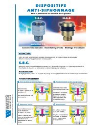
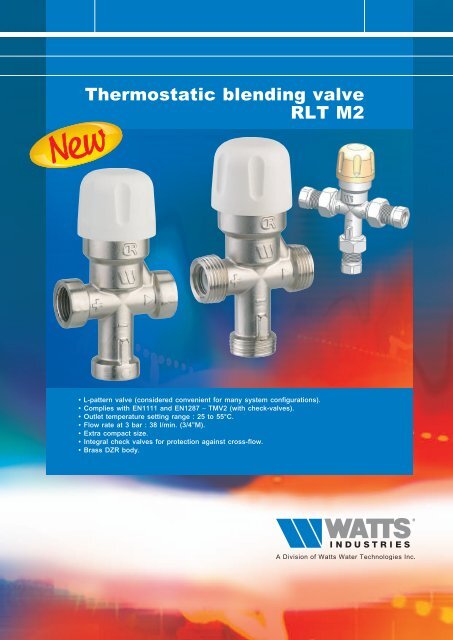
<strong>Thermostatic</strong> <strong>blending</strong> <strong>valve</strong><br />
<strong>RLT</strong> <strong>M2</strong><br />
• L-pattern <strong>valve</strong> (considered convenient for many system configurations).<br />
• Complies with EN1111 and EN1287 – TMV2 (with check-<strong>valve</strong>s).<br />
• Outlet temperature setting range : 25 to 55°C.<br />
• Flow rate at 3 bar : 38 l/min. (3/4”M).<br />
• Extra compact size.<br />
• Integral check <strong>valve</strong>s for protection against cross-flow.<br />
• Brass DZR body.
Hot<br />
water<br />
Features :<br />
THERMOSTATIC BLENDING VALVE <strong>RLT</strong> <strong>M2</strong><br />
Application :<br />
L-pattern thermostatic mixing <strong>valve</strong> for general purpose applications. <strong>RLT</strong> <strong>M2</strong> is<br />
often used for safely regulating supply temperature to hand wash basins with<br />
infra red tap.<br />
Typical hand wash basin applications could be sport halls, motorways services,<br />
domestic homes, shopping malls, or public buildings.<br />
<strong>RLT</strong> <strong>M2</strong> can be used also to control the temperature in a sanitary hot water distribution<br />
system for a domestic property.<br />
• Rapid fail safe if cold water supply is interrupted comply with EN1111 and EN1287 – TMV2 (with check-<strong>valve</strong>s).<br />
• L-pattern design can aid system configuration and reduce installation time.<br />
• Provides stable mixed water temperature.<br />
• Tamperproof setting adjustment with free “click” cover cap.<br />
• Integral check <strong>valve</strong>s for protection against cross-flow (size Female 1/2” delivered without check-<strong>valve</strong>s).<br />
• Can be installed in any position.<br />
• Nickel plated finish.<br />
Approvals :<br />
Wras (UK), ACS (F).<br />
Specifications :<br />
• G3/4” Male threaded on inlets and outlets or compression fitting 15 mm or Female 1/2”.<br />
• Pressure at the <strong>valve</strong> inlets must be within the 5:1 ratio under flow conditions.<br />
The size and layout of pipework and in-line fittings must take this into consideration.<br />
Optimum performance achieved with equal pressure.<br />
• Temperature : accurate to within 1,5°C of chosen temperature (with balanced dynamic pressure).<br />
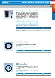
• Head loss under dynamic pressure at the mixer inlets is shown by the curve.<br />
• Maximum static pressure : 10 bar.<br />
• Operating pressure : 0,2 to 5 bar.<br />
• Hot temperature supply : 50* - 85°C, *differential minimum hot/mix temperature must be 20°C.<br />
• Cold temperature supply : 5 - 20°C.<br />
• Temperature setting range : 25 to 55°C.<br />
• Factory temperature setting : 38°C.<br />
• Flow rate at 3 bar : - 3/4”M : 38 l/min.<br />
- 1/2”F & 15mm comp. fitting : 35 l/min.<br />
• Flow mini : 5 l/min.<br />
• Body strength : 25 bar.<br />
Materials :<br />
Cold water<br />
Mixed<br />
outlet<br />
Diameter Check-<strong>valve</strong>s Finish Code ref.<br />
Male / Male / Male 3/4” yes nickel plated 97009<strong>M2</strong><br />
Compression fitting 15 mm yes nickel plated 97195<br />
Female / Female / Female 1/2” no nickel plated 97152<br />
description material<br />
Body brass DZR CW602N<br />
Finish nickel plated<br />
Spring stainless steel<br />
Piston PSU (polysulfone polymer)<br />
O-ring EPDM<br />
Check-<strong>valve</strong> POM, stainless steel and rubber<br />
Head PA with glass fiber
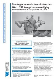
Dimensions :<br />
- Male/Male/Male 3/4” : 97009<strong>M2</strong><br />
(flat sealing)<br />
5<br />
.<br />
7<br />
1<br />
1<br />
3<br />
.<br />
4<br />
4<br />
THERMOSTATIC BLENDING VALVE <strong>RLT</strong> <strong>M2</strong><br />
32.5 32.5 32.5 32.5 32.5 32.5 32.5 32.5 32.5 32.5 32.5 32.564.5<br />
64.5 64.5 64.5 64.5<br />
64.5<br />
5<br />
.<br />
7<br />
1<br />
1<br />
3<br />
.<br />
4<br />
4<br />
44. 3<br />
environ 73<br />
44 44 44 44 44 44 44<br />
44<br />
44<br />
5<br />
.<br />
7<br />
1<br />
1<br />
3<br />
.<br />
4<br />
4<br />
How to open the cap :<br />
Tamperproof setting adjustment<br />
with free “click” cover cap.<br />
Lift under the<br />
triangle to open.<br />
by hand<br />
here<br />
here<br />
or with a screwdriver<br />
- Female/Female/Female 1/2” : 97152<br />
(delivered without check-<strong>valve</strong>s)<br />
44. 3<br />
environ 73<br />
44. 3<br />
environ 73<br />
50<br />
45<br />
40<br />
35<br />
30<br />
25<br />
20<br />
15<br />
10<br />
5<br />
0 0<br />
50<br />
45<br />
40<br />
35<br />
30<br />
25<br />
20<br />
15<br />
10<br />
5<br />
0 0<br />
fitting<br />
strainer<br />
gasket<br />
1<br />
1<br />
- Compression fitting 15 mm : 97195<br />
(delivered with integral strainers)<br />
check <strong>valve</strong><br />
Pressure drop curve / headloss :<br />
Female/Female/Female 1/2”<br />
Male/Male/Male 3/4”<br />
Compression fitting 15 mm<br />
5<br />
.<br />
2<br />
5<br />
1<br />
9<br />
9<br />
2<br />
5<br />
.<br />
2<br />
5<br />
1<br />
9<br />
9<br />
2<br />
5<br />
.<br />
2<br />
5<br />
1<br />
2 3 4 5 6<br />
9<br />
9<br />
2<br />
2 3 4 5 6
THERMOSTATIC BLENDING VALVE <strong>RLT</strong> <strong>M2</strong><br />
Installation & Temperature setting :<br />
In order to maintain the <strong>valve</strong> performances, a strainer must be installed upstream on the main water supply line to<br />
eliminate the risk due to debris.<br />
The thermostatic controller is supplied factory pre set at 38°C.<br />
However, installation conditions may dictate, that the product be adjusted on site.<br />
To adjust the temperature supply, simply remove the plastic cap on top of the <strong>valve</strong>.<br />
Manipulate the axis. - To increase the temperature turn anti-clockwise.<br />
- To decrease the temperature turn clockwise.<br />
After adjustment, replace the cap to lock the <strong>valve</strong> in position and prevent tampering.<br />
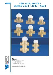
Typical installation :<br />
Hand wash basin temperature control Sanitary hot water distribution control<br />
Dielectric insulating connection<br />
<strong>Thermostatic</strong> Mixing <strong>valve</strong>s<br />
Mixed water<br />
Electrical hot water<br />
storage heater<br />
Pressure reducing <strong>valve</strong><br />
REDUFIX<br />
Safety Unit<br />
The photographs, illustrations and descriptions contained in this brochure are given for information only.<br />
<strong>Watts</strong> <strong>Industries</strong> reserves the right to change the technical specifications or the design of these products without prior notice.<br />
Hot water<br />
Cold water inlet<br />
Deflector<br />
Trap funnel kit<br />
Drainage<br />
WATTS INDUSTRIES France<br />
06, avenue Gustave Eiffel - B.P. 40339<br />
28006 CHARTRES Cedex (France)<br />
Tel. +33 (0)2 37 25 11 00 - Fax +33 (0)2 37 25 11 11<br />
E-mail info@wattsindustries.fr<br />
Site www.wattsindustries.com<br />
Re-order no. 69(19)-UK-07/09