Behaviour of steel joints under fire loading - CMM
Behaviour of steel joints under fire loading - CMM
Behaviour of steel joints under fire loading - CMM

You also want an ePaper? Increase the reach of your titles
YUMPU automatically turns print PDFs into web optimized ePapers that Google loves.
Steel and Composite Structures, Vol. 5, No. 6 (2005) 485-513 485<br />
<strong>Behaviour</strong> <strong>of</strong> <strong>steel</strong> <strong>joints</strong> <strong>under</strong> <strong>fire</strong> <strong>loading</strong><br />
Luís Simões da Silva† and Aldina Santiago‡<br />
<strong>of</strong> Civil Engineering, University <strong>of</strong> Coimbra,<br />
Department<br />
II - Pinhal de Marrocos, 3030-290 Coimbra, Portugal<br />
Polo<br />
Paulo Vila Real‡†<br />
Department <strong>of</strong> Civil Engineering, University <strong>of</strong> Aveiro, 3810 Aveiro, Portugal<br />
David Moore‡‡<br />
BCSA – British Constructional Steelwork Association, London, U.K.<br />
(Received November 11, 2004, Accepted May 25, 2005)<br />
This paper presents a state-<strong>of</strong>-the-art on the behaviour <strong>of</strong> <strong>steel</strong> <strong>joints</strong> <strong>under</strong> <strong>fire</strong> <strong>loading</strong> and some<br />
Abstract.<br />
developments in this field, currently being carried out by the authors. Firstly, a review <strong>of</strong> the<br />
recent<br />
research work on <strong>steel</strong> <strong>joints</strong> is presented, subdivided into isolated member tests, sub-structure<br />
experimental<br />
and tests on complete building structures. Special emphasis is placed on the seventh Cardington test,<br />
tests<br />
out by the authors within a collaborative research project led by the Czech Technical University in<br />
carried<br />
Secondly, a brief review <strong>of</strong> various temperature distributions within a joint is presented, followed by a<br />
Prague.<br />
<strong>of</strong> the behaviour <strong>of</strong> isolated <strong>joints</strong> at elevated temperature, focussing on failure modes and<br />
discussion<br />
procedures for predicting the moment-rotation behaviour <strong>of</strong> <strong>joints</strong> at elevated temperature. Finally,<br />
analytical<br />
description <strong>of</strong> the coupled behaviour <strong>of</strong> <strong>joints</strong> as part <strong>of</strong> complete structures is presented, describing previous<br />
a<br />
and investigations on real <strong>fire</strong> (including heating and cooling phases) currently being carried out by the<br />
work<br />
authors.<br />
words: axial restraint; component method; composite <strong>joints</strong>; experimental tests; <strong>fire</strong> engineering;<br />
Key<br />
<strong>joints</strong>; temperature.<br />
<strong>steel</strong><br />
1. Introduction<br />
behaviour <strong>of</strong> <strong>steel</strong> and composite <strong>joints</strong> <strong>under</strong> <strong>fire</strong> <strong>loading</strong> is a subject that has only recently<br />
The<br />
special attention by the research community. In fact, as recently as 1995, the European<br />
received<br />
on the <strong>fire</strong> response <strong>of</strong> <strong>steel</strong> structures (EN1993-1-2: 1995) deemed it unnecessary to assess<br />
prestandard<br />
behaviour <strong>of</strong> <strong>steel</strong> <strong>joints</strong> <strong>under</strong> <strong>fire</strong> conditions. This approach was supported by the argument <strong>of</strong> the<br />
the<br />
increased massivity <strong>of</strong> the joint area. However, observations from real <strong>fire</strong>s show that, on several<br />
Corresponding author, E-mail: luisss@dec.uc.pt<br />
†Pr<strong>of</strong>essor,<br />
Assistant, E-mail: aldina@dec.uc.pt<br />
‡Research<br />
E-mail: pvreal@civil.ua.pt<br />
‡†Pr<strong>of</strong>essor,<br />
E-mail: David.Moore@Steelconstruction.org<br />
‡‡Dr,
486 Luís Simões da Silva et al.<br />
<strong>steel</strong> <strong>joints</strong> fail, particularly their tensile components (such as bolts or end-plates) because <strong>of</strong><br />
occasions,<br />
high cooling strains induced by the distortional deformation <strong>of</strong> the connected members (Buchanan<br />
the<br />
Bailey et al. 1999, Wald et al. 2005).<br />
2002,<br />
characterize the behaviour <strong>of</strong> <strong>steel</strong> <strong>joints</strong> <strong>under</strong> <strong>fire</strong> <strong>loading</strong>, several aspects must be considered:<br />
To<br />
The time-temperature distribution in and around the joint;<br />
a)<br />
The effect <strong>of</strong> high temperatures on the structural response <strong>of</strong> the <strong>joints</strong>;<br />
b)<br />
The redistribution <strong>of</strong> internal forces with time acting on the joint from the global behaviour <strong>of</strong> the<br />
c)<br />
structure.<br />
consistent approach for the assessment <strong>of</strong> the <strong>fire</strong> response <strong>of</strong> <strong>steel</strong> <strong>joints</strong> requires a broader view<br />
A<br />
merely restricting the attention to the joint area. Two directly related aspects must be considered,<br />
than<br />
the <strong>fire</strong> development and the structural <strong>fire</strong> resistance strategy. Although essential, these aspects<br />
namely<br />
not be dealt with in detail in this paper, generic references are available (Drysdale 1999, Vila Real<br />
will<br />
2003).<br />
is the purpose <strong>of</strong> this paper to present a state-<strong>of</strong>-the-art <strong>of</strong> the behaviour <strong>of</strong> <strong>steel</strong> <strong>joints</strong> <strong>under</strong> <strong>fire</strong><br />
It<br />
<strong>loading</strong> and to describe some recent developments currently being carried out by the authors.<br />
2. Experimental research<br />
research has been used to establish the behaviour <strong>of</strong> <strong>steel</strong> structures in <strong>fire</strong> and, in<br />
Experimental<br />
<strong>steel</strong> <strong>joints</strong>. The experimental results on the response <strong>of</strong> <strong>steel</strong> connections <strong>under</strong> <strong>fire</strong><br />
particular,<br />
are relatively recent and are limited, partly because <strong>of</strong> the high cost <strong>of</strong> conducting <strong>fire</strong> tests<br />
conditions<br />
partly due to the limitations on the size <strong>of</strong> furnace used. Only a few connection tests have been<br />
and<br />
and these have concentrated on obtaining the moment-rotation relationships <strong>of</strong> isolated<br />
performed<br />
In the following, a summary <strong>of</strong> available test results is presented.<br />
connections.<br />
2.1. Tests on isolated <strong>joints</strong><br />
first reported tests on <strong>steel</strong> beam-to-column connections in <strong>fire</strong> were performed at CTICM<br />
The<br />
1976) and by the British Steel (British Steel, 1982). Both experimental projects tested a range<br />
(Kruppa<br />
“flexible” to “rigid” connections <strong>under</strong> the ISO 834 <strong>fire</strong> curve (ISO 834, 1975) and linear increases<br />
<strong>of</strong><br />
temperature. The main aim <strong>of</strong> these tests was to establish the performance <strong>of</strong> high strength bolts. The<br />
in<br />
suggested that the bolts and their connected elements could <strong>under</strong>go considerable deformations<br />
results<br />
<strong>fire</strong>. in<br />
it was in the last fifteen years that research into the behaviour <strong>of</strong> <strong>joints</strong> <strong>under</strong> <strong>fire</strong> <strong>loading</strong><br />
However,<br />
significant developments. Lawson (1990) was the first to quantify the benefits <strong>of</strong> structural<br />
experienced<br />
<strong>under</strong> <strong>fire</strong> conditions on the basis <strong>of</strong> the results from a series <strong>of</strong> <strong>fire</strong> tests on typical beam-to-<br />
continuity<br />
connections. The tests were set up to fit within the test furnace at the Warrington Fire Research<br />
column<br />
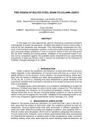
The cruciform test arrangement was used, comprising beams connected to a column, as shown<br />
Centre.<br />
Fig. 1. in<br />
tests were carried out <strong>under</strong> the standard temperature-time <strong>fire</strong> curve ISO 834. These tests<br />
Eight<br />
four flush end-plate <strong>joints</strong> (two using <strong>steel</strong> beams, one composite beams and one shelf-angle<br />
included<br />
two extended end-plate <strong>joints</strong> (both using <strong>steel</strong> beams) and two web-cleat <strong>joints</strong> (one using<br />
beams),<br />
beams and one composite beams). All the beams supported concrete or a concrete slab. However,<br />
<strong>steel</strong><br />
they were each restricted to a single load level (two load levels in three cases), providing insufficient
<strong>Behaviour</strong> <strong>of</strong> <strong>steel</strong> <strong>joints</strong> <strong>under</strong> <strong>fire</strong> <strong>loading</strong> 487<br />
Fig. 1 Arrangement <strong>of</strong> the <strong>fire</strong> tests on beam-to-column connections (Lawson 1990)<br />
for the construction <strong>of</strong> the moment-rotation curves. This single load level varied between 0.10 Mp<br />
data<br />
0.40 Mp, Mp - being the plastic moment capacity <strong>of</strong> the <strong>steel</strong> beam. From the experimental<br />
and<br />
it was found that the temperatures in the joint were much lower than that <strong>of</strong> the lower<br />
observations,<br />
<strong>of</strong> the <strong>steel</strong> beam, which is usually the element that defines the limiting temperature <strong>of</strong> the beam.<br />
flange<br />
maximum temperature on the lower beam flange was about 650 to 750 The o and the maximum<br />
C<br />
in the upper exposed bolts was 150 to 200 temperature o lower, and those inside the concrete slab were<br />
C<br />
200 to 350 about o lower than the lower beam flange. Failure was due to large deformation <strong>of</strong> the end-<br />
C<br />
In addition, it was suggested that composite action at elevated temperature contributed to the<br />
plate.<br />
moment capacity <strong>of</strong> the connections. This was estimated by adding together the moment<br />
enhanced<br />
<strong>of</strong> the bare-<strong>steel</strong> connection and the reinforced concrete slab.<br />
capacities<br />
first characterization at high temperatures <strong>of</strong> the moment-rotation behaviour <strong>of</strong> commonly used<br />
The<br />
was performed within a collaborative research programme involving the Building Research<br />
<strong>joints</strong><br />
the University <strong>of</strong> Sheffield and the Steel Construction Institute in the UK. This<br />
Establishment,<br />
was divided into two phases; firstly, the behaviour <strong>of</strong> specimens with only one joint<br />
programme<br />
was investigated (Leston-Jones et al. 1997); and secondly, the scope <strong>of</strong> the experimental<br />
configuration<br />
was extended to include parameters such as member size, connection type and different<br />
programme<br />
mechanisms (Al-Jabri et al. 1998, Al-Jabri 1999).<br />
failure<br />
the first phase, a total <strong>of</strong> eleven tests were conducted, including two tests at room temperature, for<br />
In<br />
bare-<strong>steel</strong> and composite <strong>joints</strong>. The scope <strong>of</strong> the programme was restricted to cruciform<br />
both<br />
with flush endplates (the most common connection type used in non-composite building<br />
connections<br />
The high temperature tests were performed on a furnace that consisted <strong>of</strong> four ‘barrel’ modules<br />
frame).<br />
for testing beams or columns, and a junction furnace designed for testing connections within a<br />
suitable
488 Luís Simões da Silva et al.<br />
Fig. 2 High temperature test: schematic arrangement (Leston-Jones et al. 1997)<br />
or three-dimensional framework. The high temperature test arrangement is illustrated in Fig. 2. In<br />
twoto<br />
create a temperature distribution across the connection representative <strong>of</strong> real conditions, the<br />
order<br />
slab was simulated by a 50 mm thick ceramic fibre blanket wrapped around the top flange <strong>of</strong><br />
concrete<br />
beam. All tests were performed by applying a fixed bending moment with a subsequent increase <strong>of</strong><br />
the<br />
furnace temperature at a rate <strong>of</strong> about 10 the o while maintaining the applied load.<br />
C/min<br />
tests results at room temperature have shown significant deformation <strong>of</strong> the column web in the<br />
The<br />
zone and <strong>of</strong> the column flange in the tension zone. Very little damage to the beams, plates<br />
compression<br />
bolts was observed. The joint was capable <strong>of</strong> resisting moments in excess <strong>of</strong> 30 kNm, with a<br />
or<br />
limit <strong>of</strong> about 15 kNm. Observation from the high-temperature tests showed an almost<br />
proportional<br />
temperature pr<strong>of</strong>ile through the depth <strong>of</strong> the connection. The uniform heating combined with the<br />
linear<br />
slow rate <strong>of</strong> heating provided a somewhat unrepresentative <strong>fire</strong> condition when compared to a<br />
relatively<br />
building <strong>fire</strong>. The failure modes observed at high temperatures were similar to those at room<br />
typical<br />
It was also observed that both the moment capacity and stiffness <strong>of</strong> the connection<br />
temperature.<br />
with temperature. The critical temperature range <strong>of</strong> the connection, at which there is a market<br />
degraded<br />
in capacity, was between 500-600ºC.<br />
downturn<br />
the second phase (Al-Jabri et al. 1998, Al-Jabri 1999), the general arrangement for the high<br />
In<br />
tests was the same as for the Leston-Jones tests (Fig. 2). In all cases, the test specimens<br />
temperature<br />
<strong>of</strong> a symmetric cruciform arrangement <strong>of</strong> a single column 2.7 m high with two cantilever<br />
consisted<br />
1.9 m long, connected on either side <strong>of</strong> the column flange. The programme <strong>of</strong> work is summarized<br />
beams<br />
Table 1. The small member sizes associated with Group 1 tests were chosen for comparison with the<br />
in<br />
Leston-Jones tests, the only difference being the adoption <strong>of</strong> a more realistically sized end-plate thickness
Table 1 High temperature connections tests.<br />
<strong>Behaviour</strong> <strong>of</strong> <strong>steel</strong> <strong>joints</strong> <strong>under</strong> <strong>fire</strong> <strong>loading</strong> 489<br />
Group Beam Column End-plate Material Load Level<br />
1 254×102×22UB 152×152×23UC flush end-plate, t P = 8 mm bare <strong>steel</strong><br />
2 356×171×51UB 254×254×89UC flush end-plate, t P = 10 mm bare <strong>steel</strong><br />
3 356×171×51UB 254×254×89UC header-plate, t P = 8 mm bare <strong>steel</strong><br />
4 356×171×51UB 254×254×89UC header-plate, t P = 8 mm composite<br />
5 356×171×51UB 254×254×89UC header-plate, t P = 10 mm composite<br />
M c1 = 20 kNm; M c2 = 140 kNm; M c3 = 60 kNm; M c4 = 105 kNm; M c5 = 227 kNm<br />
8 mm. The larger section sizes and variation in connection types associated with the bare <strong>steel</strong> tests<br />
<strong>of</strong><br />
Groups 2 and 3 reflect the adoption <strong>of</strong> connections used in the eight storey building at Cardington.<br />
in<br />
4 and 5 extend this philosophy to include the behaviour <strong>of</strong> the composite slab.<br />
Groups<br />
showed little variation in temperature across the bare <strong>steel</strong> connections. However, in the<br />
Observations<br />
connections, the concrete slab acted as a radiation shield and a heat sink, keeping the upper<br />
composite<br />
cooler and thus enhancing the failure temperature <strong>of</strong> the lower beam flange. The observed failure<br />
flange<br />
depended on the connection type: in group 1, localized deformation at the top <strong>of</strong> the end-plate<br />
modes<br />
observed, particularly around the top bolt, accompanied by deformation <strong>of</strong> the column flange and<br />
was<br />
<strong>of</strong> the column web. In group 2 localized deformations occurred at the top <strong>of</strong> the end-plate,<br />
buckling<br />
<strong>of</strong> the top bolts in the tension zone (maybe due s<strong>of</strong>tening <strong>of</strong> the bolts at elevated temperatures);<br />
slipping<br />
high moment levels, cracking <strong>of</strong> the end-plate along the welds was observed in both the beam web<br />
at<br />
flange. In group 3 significant end-plate deformation was developed. In groups 4 and 5 failure in the<br />
and<br />
slab (due to separation <strong>of</strong> the shear stubs from the concrete slab) was observed. After failure <strong>of</strong><br />
concrete<br />
concrete slab, the applied load was transferred to the connection and end-plate failure was observed.<br />
the<br />
general, all high temperature tests produced failure modes similar to those <strong>of</strong> the same connections at<br />
In<br />
temperature.<br />
room<br />
in order to assess the individual behaviour <strong>of</strong> each component <strong>of</strong> an end-plate connections<br />
Recently,<br />
high temperatures, Spyrou et al. (2004a, 2004b) carried out an experimental programme on T-Stub<br />
at<br />
column web components using an electric furnace, where the temperature ranged from 20 to<br />
and<br />
Twenty five specimens were tested to investigate the three failure modes <strong>of</strong> the T-Stub and<br />
800ºC.<br />
nine tests were conducted on the column web in compression. The tests at high temperature<br />
twenty<br />
the bolt flexibility as a key parameter in the behaviour <strong>of</strong> the T-Stub. On the compression<br />
highlighted<br />
tests, some discrepancies were highlighted between the capacities calculated using the current<br />
zone<br />
standards and the experimental results at room temperature.<br />
design<br />
2.2. Tests on sub-structures<br />
tests: 0.2 Mc1; 0.4 Mc1; 4<br />
Mc1; 0.8 Mc1. 0.6<br />
tests: 0.2 Mc2; 0.4 Mc2; 4<br />
Mc2; 0.8 Mc2. 0.6<br />
tests: 0.2 Mc3; 0.4 Mc3; 3<br />
Mc3. 0.6<br />
tests: 0.2 Mc4; 0.4 Mc4; 5<br />
Mc4; 0.6 Mc4; full.<br />
0.6<br />
tests: 0.2 Mc5; 0.4 Mc5; 4<br />
Mc5; 0.8 Mc5. 0.6<br />
stated before, isolated member tests do not truly reflect the behaviour <strong>of</strong> a member <strong>under</strong> either<br />
As<br />
or <strong>fire</strong> conditions. Many aspects only occur when <strong>steel</strong> members are connected together. Global<br />
normal<br />
local failure and the force redistribution capability <strong>of</strong> highly redundant structural systems are some<br />
and<br />
the features occurring when the members interact with each other which cannot be represented by<br />
<strong>of</strong>
490 Luís Simões da Silva et al.<br />
element testing (Armer et al. 1994). In addition, other effects can be observed, as the behaviour<br />
isolated<br />
with restraint to thermal expansion caused by the adjacent cooler structure, increases the<br />
associated<br />
force in the heated members. This can cause column instability (Bailey et al. 1996) and local<br />
axial<br />
in the heated beams, neither <strong>of</strong> which would occur in isolated members.<br />
buckling<br />
Germany, Rubert and Schaumann (1986) used electrical heating to test a series <strong>of</strong> three different<br />
In<br />
<strong>of</strong> quarter-to-half scale sub-assemblies rigidly connected. No information was provided<br />
arrangements<br />
the forces in the test frames to enable quantification <strong>of</strong> the effect between different frame members.<br />
on<br />
these high temperature tests have been used by various researchers to validate numerical<br />
Nevertheless,<br />
models.<br />
the same time, the Fire Research Station, UK, carried out perhaps the first <strong>fire</strong> test on a full-scale<br />
At<br />
assembly subjected to a natural <strong>fire</strong> using wooden cribs (Cooke and Latham 1987). The test<br />
structural<br />
was a goal post assembly consisting <strong>of</strong> a <strong>steel</strong> beam (406×178×54 UB) and two <strong>steel</strong> columns<br />
structure<br />
UC). The column bases were pinned and the beam was connected to the columns using<br />
(203×203×52<br />
end-plate connections. A concrete slab was placed on top <strong>of</strong> the <strong>steel</strong> beam to give realistic<br />
flush<br />
conditions. Bracing was provided to the test frame near the beam-to-column connections to<br />
heating<br />
sway and out-<strong>of</strong>-plane deflections. This test showed that the performance <strong>of</strong> the frame was<br />
prevent<br />
than that <strong>of</strong> the individual elements as a result <strong>of</strong> the continuity between the beam and columns.<br />
better<br />
the end <strong>of</strong> 1990’s, the University <strong>of</strong> Manchester developed an experimental project in order to<br />
At<br />
the effects <strong>of</strong> restraint to thermal expansion <strong>of</strong> unprotected beams, from protected columns<br />
investigate<br />
adjacent cooler beams (Liu et al. 2002). These tests focused on the effect that different connection<br />
and<br />
had on the failure temperature <strong>of</strong> the connected members at different load levels. The<br />
types<br />
work was based on two-dimensional studies and was complemented with the results from<br />
experimental<br />
Cardington full-scale frame <strong>fire</strong> tests. In total, 25 <strong>fire</strong> tests on 2D <strong>steel</strong> frames were conducted. Two<br />
the<br />
<strong>of</strong> connections were considered: flush end-plate and web cleat connections, coupled with three<br />
types<br />
<strong>of</strong> <strong>loading</strong> (20%, 50% and 70% <strong>of</strong> the moment capacity <strong>of</strong> the beam) and three degrees <strong>of</strong><br />
levels<br />
restraint (8 kN/m; 35 kN/m and 62 kN/m). The beams had varying amounts <strong>of</strong> insulation,<br />
horizontal<br />
the case in which the lower flange was fully exposed and the upper flange was encased in a<br />
including<br />
slab. The columns were generally <strong>fire</strong>-protected and a section <strong>of</strong> the beam and column in the<br />
concrete<br />
<strong>of</strong> the connection was exposed to <strong>fire</strong>. The top flange <strong>of</strong> the beam was protected by a non-<br />
region<br />
concrete slab. The major axis connection configuration consisted <strong>of</strong> a 178×102×19UB beam<br />
composite<br />
connected to a 152x152x30UC column, both in grade 43 (S 275) <strong>steel</strong>.<br />
Fig. 3 (a) High temperature test, (b) Section through furnace (Liu et al. 2002)
<strong>Behaviour</strong> <strong>of</strong> <strong>steel</strong> <strong>joints</strong> <strong>under</strong> <strong>fire</strong> <strong>loading</strong> 491<br />
basic layout <strong>of</strong> the furnace and the specimens are illustrated in Fig. 3(a). The furnace box was<br />
The<br />
<strong>of</strong> light rectangular hollow <strong>steel</strong> sections supporting thin <strong>steel</strong> plates with ceramic fibre<br />
constructed<br />
(with rapid heating times and light-weight construction). To expose the <strong>steel</strong> frame to uniform<br />
lining<br />
but to prevent direct exposure to the flame itself, the furnace box was partially divided by a<br />
heating<br />
fibre partition, as shown in Fig. 3(b). The burning system was programmed to follow the ISO<br />
ceramic<br />
<strong>fire</strong> curve.<br />
834<br />
showed a small variation in temperature in the web and bottom flange. Due to the <strong>fire</strong><br />
Observations<br />
around the top flange, its temperature initially rose at a slower rate, the temperature<br />
protection<br />
between the top flange and the web being about 300 difference o after 10 min. This difference was<br />
C<br />
reduced to 100 subsequently o when the web temperatures reached 800 C o It was recognized that<br />
C.<br />
connections had very little influence on the behaviour <strong>of</strong> the beam until the beam came<br />
web-cleat<br />
contact with the column. Flush end-plate connections were able to transfer a much higher<br />
into<br />
moment to the column than the web-cleat connections. In some tests (those with higher axial<br />
bending<br />
and lower load levels), catenary action at large deflections was clearly visible (Liu et al.<br />
restraint<br />
2001a).<br />
2.3. Tests on complete building structures and observation <strong>of</strong> real <strong>fire</strong> events<br />
tests on sub-structures are necessary to <strong>under</strong>stand the interaction between different structural<br />
Fire<br />
and to appreciate the difference between the behaviour <strong>of</strong> isolated members and members<br />
members<br />
a structure. However, in addition to the structural members a complete structure also includes<br />
within<br />
slabs, walls and others non-structural members. A proper <strong>under</strong>standing <strong>of</strong> the behaviour <strong>of</strong> a<br />
floor<br />
building in <strong>fire</strong> can only be obtained if all such components are included. Although extremely<br />
complete<br />
<strong>fire</strong> tests on complete buildings are essential, complemented with the investigation <strong>of</strong><br />
expensive,<br />
<strong>fire</strong> events in buildings. Crucial to the <strong>under</strong>standing <strong>of</strong> the structural behaviour <strong>of</strong> a<br />
accidental<br />
building in a real <strong>fire</strong> are the Broadgate <strong>fire</strong> accident (SCI, 1991) and the Cardington full-<br />
complete<br />
<strong>fire</strong> tests (Armer et al. 1994, Bailey et al. 1999, Wang 2002). Others tests and real <strong>fire</strong>s included<br />
scale<br />
William street <strong>fire</strong> tests by BHP (Thomas et al. 1992) and the Collin street <strong>fire</strong> test by BHP (Proe<br />
the<br />
Bennetts 1994) in Australia, the Basingstoke <strong>fire</strong> accident and the Churchill Plaza <strong>fire</strong> accident in<br />
and<br />
United Kingdom, the <strong>fire</strong> tests performed in Germany (Anon 1986) and the <strong>fire</strong> event at the World<br />
the<br />
Center, NY (Usmani et al. 2003, Quintiere et al. 2002). In the following paragraph, the<br />
Trade<br />
full-scale <strong>fire</strong> tests will be described in more detail.<br />
Cardington<br />
Cardington Laboratory is a unique worldwide facility for the advancement <strong>of</strong> <strong>under</strong>standing <strong>of</strong><br />
The<br />
performance. This facility is located at Cardington, Bedfordshire, UK and consists <strong>of</strong> a<br />
whole-building<br />
airship hangar with dimensions 48 m×65 m×250 m. It is used by industrial organizations,<br />
former<br />
and research institutes, government departments and their agencies. The BRE’s Cardington<br />
universities<br />
comprises three experimental buildings: a six storey timber structure, a seven storey<br />
Laboratory<br />
structure and an eight storey <strong>steel</strong> structure.<br />
concrete<br />
eight storey <strong>steel</strong> structure was built in 1993. It is a <strong>steel</strong> framed construction using composite<br />
The<br />
slabs supported by <strong>steel</strong> decking in composite action with the <strong>steel</strong> beams (Fig. 4). It has eight<br />
concrete<br />
(33 m) and is five bays wide (5×9 m = 45 m) by three bays deep (6 + 9 + 6 = 21 m) in plan, see<br />
storeys<br />
5. The structure was built as a no-sway frame with a central lift shaft and two end staircases<br />
Fig.<br />
the necessary resistance against lateral wind loads. The main <strong>steel</strong> frame was designed for<br />
providing<br />
loads, the <strong>joints</strong> consisting <strong>of</strong> flexible end plates for beam-to-column connections and fin plates<br />
gravity<br />
for beam-to-beam connections, designed to transmit vertical shear loads. The building simulates a real
492 Luís Simões da Silva et al.<br />
Fig. 4 The eight storey <strong>steel</strong> structure in Cardington<br />
Fig 5. The Cardington <strong>fire</strong> tests on <strong>steel</strong> structure<br />
<strong>of</strong>fice in the Bedford area and all the elements were designed according to British<br />
commercial<br />
and checked for compliance with the provisions <strong>of</strong> the Structural Eurocodes.<br />
Standards<br />
building was designed for a dead load <strong>of</strong> 3.65 kN/m The 2 an imposed load <strong>of</strong> 3.5 kN/m and 2 (Bravery<br />
The floor construction consisted <strong>of</strong> a <strong>steel</strong> deck and a light-weight in-situ concrete composite<br />
1993).<br />
incorporating an A142 (142 mm floor, 2 anti-crack mesh in both directions. The floor slab had an<br />
/m)<br />
depth <strong>of</strong> 130 mm and the <strong>steel</strong> decking had a trough depth <strong>of</strong> 60 mm.<br />
overall
<strong>Behaviour</strong> <strong>of</strong> <strong>steel</strong> <strong>joints</strong> <strong>under</strong> <strong>fire</strong> <strong>loading</strong> 493<br />
Table 2 Fire tests on the <strong>steel</strong> structure in the Cardington laboratory (Wald et al. 2005).<br />
No. Test<br />
compartment Load<br />
Fire<br />
m area, m size, 2<br />
Mechanical<br />
Fire<br />
One beam heated by gas 8×3 24 Gas 30%<br />
1<br />
One frame heated by gas 21×2.5 53 Gas 30%<br />
2<br />
Corner compartment 9×6 54 40 kg/m 3 2<br />
Corner compartment 10×7 70 45 kg/m 4 2<br />
Large compartment 21×18 342 40 kg/m 5 2<br />
Office – Demonstration 18×9 136 45 kg/m 6 2<br />
7 Structural integrity 11×7 77 40 kg/m 2<br />
large-scale structural <strong>fire</strong> tests at various positions within the experimental building were<br />
Seven<br />
see Fig. 5 and Table 2 (Moore 1995, O’Conner and Martin 1998, Bailey et al. 1999, Wald<br />
conducted;<br />
al. 2005). The main objective <strong>of</strong> the compartment <strong>fire</strong> tests was to assess the behaviour <strong>of</strong> structural<br />
et<br />
with real restraint <strong>under</strong> a natural <strong>fire</strong>.<br />
elements<br />
first test performed at Cardington was a restrained beam test involving a single 305x165xUB40<br />
The<br />
beam section supporting part <strong>of</strong> the seventh floor <strong>of</strong> the building (Lennon 1997). A gas-<strong>fire</strong>d<br />
composite<br />
was used to heat the beam to approximately 900 furnace o The second test, a plane frame test,<br />
C.<br />
heating a series <strong>of</strong> beams and columns across the full width <strong>of</strong> the building. Again, a gas-<strong>fire</strong>d<br />
involved<br />
was used to heat the <strong>steel</strong>work to approximately 800 furnace o The BRE corner compartment test was<br />
C.<br />
first natural <strong>fire</strong> carried out at the Cardington Laboratory, representing a typical <strong>of</strong>fice <strong>fire</strong> (timber<br />
the<br />
were used to provide a <strong>fire</strong> load <strong>of</strong> 40 kg/m cribs 2 The internal compartment walls were constructed<br />
).<br />
<strong>fire</strong> resistant board, one external wall was solid brick and the other external was formed by<br />
using<br />
glazing windows. All columns were protected up to and including the connections. It was<br />
double<br />
that the <strong>fire</strong> development was largely influenced by the lack <strong>of</strong> oxygen in the compartment<br />
observed<br />
and Lennon 1997). The fourth test, the BS corner compartment test also used timber cribs to<br />
(Moore<br />
a <strong>fire</strong> load <strong>of</strong> 45 kg/m provide 2 In this test, both the perimeter beams and the columns were <strong>fire</strong><br />
.<br />
with the internal beam unprotected. Load bearing concrete blocks were used for the<br />
protected<br />
walls. The fifth test was the largest compartment <strong>fire</strong> test in the world. The compartment<br />
compartment<br />
designed to represent a modern open-plan <strong>of</strong>fice (18 m × 21 m). The compartment was bounded by<br />
was<br />
resistant walls. The main aim <strong>of</strong> this test was to investigate the ability <strong>of</strong> a large area <strong>of</strong> composite<br />
<strong>fire</strong><br />
to support the applied load once the main beams had failed. Consequently, none <strong>of</strong> the beams had<br />
slab<br />
<strong>fire</strong> protection and all columns were <strong>fire</strong> protected. Again, the ventilation conditions governed the<br />
any<br />
severity. In the demonstration test (sixth test), unlike in the previous tests, real furniture (desks,<br />
<strong>fire</strong><br />
filling cabinets, computer terminals, etc.) was used for the <strong>fire</strong> load. The ventilation was<br />
chairs,<br />
by windows and blank openings. The beams were unprotected while the columns were<br />
provided<br />
This test was characterized by a rapid rise in temperature representing a severe <strong>fire</strong> scenario.<br />
protected.<br />
the seventh test, the structural integrity <strong>fire</strong> test, had the highest amount <strong>of</strong> mechanical <strong>loading</strong><br />
Finally,<br />
was carried out by the authors. It was developed in order to investigate the global structural<br />
and<br />
<strong>of</strong> <strong>steel</strong>-concrete composite frame building subject to a natural <strong>fire</strong> test, focusing on the<br />
behaviour<br />
<strong>of</strong> the temperature development within the various structural elements, the corresponding<br />
examination<br />
distribution <strong>of</strong> internal forces and the behaviour <strong>of</strong> the composite slab, beams, columns and<br />
(dynamic)<br />
The <strong>fire</strong> test was performed on the 4 connections. th enclosing a plan area <strong>of</strong> 11 m by 7 m and it<br />
floor,<br />
was bounded with three layers <strong>of</strong> plasterboard and an opening 1.27 m × 9 m long simulating an open<br />
30%<br />
30%<br />
30%<br />
30%<br />
56%
494 Luís Simões da Silva et al.<br />
6 7 Fig. th <strong>fire</strong> test - compartment after <strong>fire</strong>, residual deformation 925 mm, no local collapse <strong>of</strong><br />
Cardington<br />
structure<br />
The columns, external <strong>joints</strong> and edge beam were <strong>fire</strong> protected to prevent global structural<br />
window.<br />
The mechanical load was simulated using sandbags, each weighing 1100 kg and the <strong>fire</strong> load<br />
instability.<br />
provided by 40 kg/m was 2 wooden cribs. During the test, the predicted local collapse <strong>of</strong> the structure<br />
<strong>of</strong><br />
not reached (Fig. 6). The maximum deflection was about 1 200 mm and the residual deflection was<br />
was<br />
mm. Fig. 7 compares the temperatures recorded in the compartment with the parametric curve<br />
925<br />
according to prEN1991-1-2 (2002). The maximum recorded compartment temperature near<br />
calculated<br />
wall (2 250 mm from D2) was 1107.8 the o after 54 minutes, while the predicted temperature was 1078<br />
C<br />
C after 53 min. The main damage mechanisms observed near the connections can be summarised as<br />
o<br />
local buckling <strong>of</strong> the beam lower flange, shear buckling <strong>of</strong> the beam web, buckling <strong>of</strong> the<br />
follows:<br />
flange in compression, fracture <strong>of</strong> the end-plate along the welds, elongation <strong>of</strong> the holes in the<br />
column<br />
web, fracture in the concrete slab and slippage <strong>of</strong> the mesh. A detailed description <strong>of</strong> this <strong>fire</strong> test<br />
beam<br />
be found in Wald et al. (2005).<br />
can<br />
Fig. 7 7 th Cardington <strong>fire</strong> test - compartment temperature
<strong>Behaviour</strong> <strong>of</strong> <strong>steel</strong> <strong>joints</strong> <strong>under</strong> <strong>fire</strong> <strong>loading</strong> 495<br />
Table 3 Summary <strong>of</strong> the results from the major full-scale <strong>fire</strong> tests in the Cardington laboratory<br />
No. Org. Level<br />
min Time,<br />
max. temp.<br />
to<br />
The main results from the Cardington tests are summarized in Table 3.<br />
3. Experimental behaviour <strong>of</strong> <strong>joints</strong> at high temperature<br />
experimental results presented above provided information on the temperature distribution<br />
The<br />
and around the joint area as well as the characterization <strong>of</strong> the moment-rotation relationship at<br />
within<br />
temperatures, including some insight into the various failure modes. In the following sections,<br />
high<br />
aspects are summarized.<br />
both<br />
3.1. Temperature distribution within the joint<br />
temperature (°C) Deformations (mm)<br />
Maximum<br />
<strong>steel</strong> maximal residual<br />
gas<br />
*BS 7 170 913 875 232 113<br />
1<br />
BS 4 125 820 800 445 265<br />
2<br />
**BRE 3 114 1000 903 269 160<br />
3<br />
BS 2 75 1020 950 325 425<br />
4<br />
BRE 3 70 - 691 557 481<br />
5<br />
BS 2 40 1150 1060 610 -<br />
6<br />
7 ***HPRI-CV 5535 4 55 1108 1088 > 1000 925<br />
– British Steel (now Corus); **BRE – Building Research Establishment; ***HPRI-CV 5535 –<br />
*BS<br />
European project.<br />
Collaborative<br />
thermal conductivity <strong>of</strong> <strong>steel</strong> is high. However, because <strong>of</strong> the mass concentration within the<br />
The<br />
area, a differential temperature distribution should be considered within the joint. Various<br />
joint<br />
distributions have been proposed or used in experimental tests by several authors.<br />
temperature<br />
to EN 1993-1-2: 2005, the temperature <strong>of</strong> a joint may be assessed using the local section<br />
According<br />
(A/V) <strong>of</strong> the joint components or calculated using the maximum value <strong>of</strong> the ratios A/V <strong>of</strong> the<br />
factor<br />
<strong>steel</strong> members. For beam-to-column and beam-to-beam <strong>joints</strong>, where the beams support any<br />
adjacent<br />
<strong>of</strong> concrete floor, the temperature may be calculated based on the temperature <strong>of</strong> the bottom flange<br />
type<br />
mid span. However, some recent studies do not support the EN 1993-1-2 recommendations. For<br />
at<br />
Franssen (2002) has shown that the temperature in the components is higher than the local<br />
example,<br />
would have indicated, probably because the dimensions <strong>of</strong> the components are <strong>of</strong> an order <strong>of</strong><br />
massivity<br />
smaller than the dimensions <strong>of</strong> the connected members and the influence <strong>of</strong> these members<br />
magnitude<br />
felt on the components.<br />
is<br />
were used in some <strong>of</strong> the previous tests in order to quantify the temperature<br />
Thermocouples<br />
within a joint. Table 4 summarizes the results, a detailed description being found in<br />
distribution<br />
literature. It shows that for deeper beams a web temperature similar to bottom flange<br />
the<br />
is observed while for small beams a smaller web temperature is observed.<br />
temperature<br />
the presence <strong>of</strong> the concrete slab above a joint causes a reduction in the temperature<br />
Additionally,<br />
the beam top flange.<br />
<strong>of</strong>
496 Luís Simões da Silva et al.<br />
Table 4 Temperature distribution with time within joint<br />
Authors Temperature distribution Main contribution<br />
Kruppa<br />
(1976)<br />
Lawson<br />
(1990)<br />
SCI<br />
recom.<br />
(1990)<br />
Leston-<br />
Jones<br />
al. et<br />
(1997)<br />
Al-Jabri<br />
al. et<br />
(1998)<br />
<strong>of</strong> IPE500 on the top flange:<br />
Half<br />
joint (web) ≈150 - 200 ºC lower than θ (web beam)<br />
θ<br />
joint (flanges) ≈ 150 - 400 ºC lower than θ (beam flanges)<br />
θ<br />
and flush end-plate <strong>joints</strong>:<br />
Fin-plate<br />
θ joint (web) ≈ θ (web beam)<br />
θ joint (flanges) ≈ 50 ºC lower than θ (beam flanges)<br />
end-plate <strong>joints</strong>:<br />
Extended<br />
joint (flanges) ≈ 50 ºC lower than θ (beam flanges)<br />
θ<br />
on the flanges and web:<br />
Web-cleats<br />
joint (flanges) θ ≈ 250 ºC lower than θ flanges)<br />
(beam<br />
on the flanges and web (column - HEB340):<br />
Web-cleats<br />
joint (web) ≈ 100 ºC lower than θ (web beam)<br />
θ<br />
θ joint (flanges) ≈ 150 ºC to 200ºC lower than θ (beam flanges)<br />
fb = 650 - 750 ºC (failure temperature)<br />
θ<br />
exposed upper bolts = 150 - 200 ºC lower than θ fb<br />
θ<br />
θ bolts inside the concrete slab = 200 - 350 ºC lower than θ fb<br />
θ lower bolts = 100 - 150 ºC higher than θ upper bolts<br />
Joint with extended end-plate, considering embedded top bolts:<br />
θupper beam flange 0.677 × θfb ;<br />
θ beam centre web<br />
θtop bolt<br />
θmiddle bolt<br />
θ bottom bolt<br />
θcolumn flange<br />
θend plate<br />
× θfb ; 0.985<br />
× θfb 0.928 ;<br />
× θfb; 0.987<br />
× θfb ;<br />
0.966<br />
× θfb 1.036 ;<br />
× θfb 0.982<br />
connection elements: column web.<br />
Hottest<br />
web (1.08 to 1.26) × θfb θcolumn ;<br />
θbeam top flange – compos joint(0.7-0.8) × θbeam top flange-<strong>steel</strong> joint<br />
measurements <strong>of</strong> the temperature<br />
First<br />
around the joint area.<br />
distribution<br />
<strong>of</strong> calibration: Isolated <strong>fire</strong> test -<br />
Scope<br />
beam-to-column connections (beam:<br />
<strong>steel</strong><br />
IPE360; column: HEB340).<br />
<strong>of</strong> the temperature distribu-<br />
Measurements<br />
in the joint components.<br />
tion<br />
<strong>of</strong> the concrete slab on the<br />
Influence<br />
distribution.<br />
temperature<br />
<strong>of</strong> calibration: Isolated <strong>fire</strong> test - <strong>steel</strong><br />
Scope<br />
composite beam-to-column connections.<br />
and<br />
<strong>of</strong> the temperature distribution<br />
Description<br />
each joint component.<br />
in<br />
<strong>of</strong> calibration: Isolated <strong>fire</strong> test -<br />
Scope<br />
double-sided joint with flush end-<br />
<strong>steel</strong><br />
plate.<br />
<strong>of</strong> the concrete slab on the joint<br />
Influence<br />
distribution.<br />
temperature<br />
<strong>of</strong> calibration: Isolated <strong>fire</strong> test -<br />
Scope<br />
and composite beam-to-column con-<br />
<strong>steel</strong><br />
nections.
Table 4 Continued<br />
<strong>Behaviour</strong> <strong>of</strong> <strong>steel</strong> <strong>joints</strong> <strong>under</strong> <strong>fire</strong> <strong>loading</strong> 497<br />
Authors Temperature distribution Main contribution<br />
et al. Liu<br />
(2002)<br />
Wald<br />
al. et<br />
(2004)<br />
EN<br />
1993-1-2<br />
(2005)<br />
θ connection 0.8 × θ beam mid-span<br />
phase, the joint temperature is significantly<br />
Heating<br />
than the remote bottom flange; in contrast, the<br />
lower<br />
down in the <strong>joints</strong> was slower.<br />
cooling<br />
the max. ambient temperature: θ joint For ≈ 200o lower than<br />
C<br />
fb θ<br />
first bolt row from the top was significantly cooler<br />
The<br />
the lower bolts.<br />
than<br />
end-plate was hotter than the bolts.<br />
The<br />
temperature <strong>of</strong> a joint may be assessed using:<br />
The<br />
the local massivity value (A/V) <strong>of</strong> the joint components, or<br />
·<br />
<strong>of</strong> calibration: Fire tests in restrained<br />
Scope<br />
beams <strong>steel</strong><br />
<strong>of</strong> the temperature<br />
Description<br />
in each joint component<br />
distribution<br />
during a natural <strong>fire</strong>.<br />
<strong>of</strong> calibration: Full-scale <strong>fire</strong> test –<br />
Scope<br />
plate beam-to-column and fin plate<br />
header<br />
beam-to-beam<br />
the maximum value <strong>of</strong> the ratios A/V <strong>of</strong> the adjacent <strong>steel</strong> members.<br />
·<br />
For beam-to-column and beam-to-beam <strong>joints</strong>, where the beams are supporting any type <strong>of</strong> con<br />
·<br />
crete floor:<br />
θ fb − Lower beam flange temperature<br />
3.2. Failure modes<br />
general, the high temperature tests on isolated <strong>steel</strong> <strong>joints</strong> produced failure modes which are<br />
In<br />
to those observed for the same joint at room temperature. However, during a natural <strong>fire</strong> on a<br />
similar
498 Luís Simões da Silva et al.<br />
Fig. 8 (a) Beam web in shear and local buckling <strong>of</strong> beam lower flange; (b) End-plate fracture<br />
building, the joint behaviour is influenced by the restrained forces due to the interaction<br />
framed<br />
the <strong>fire</strong>-affected members and the adjacent structure. In the following section the main failure<br />
between<br />
observed during the experiments above are presented:<br />
modes<br />
joint tests:<br />
Steel<br />
Header end-plate joint: 1 - Significant end-plate deformation (Al-Jabri et al. 1998).<br />
(i)<br />
Flush end-plate joint: 1- Localized deformation at the top <strong>of</strong> the end-plate, accompanied by<br />
(ii)<br />
<strong>of</strong> the column flange and buckling <strong>of</strong> the column web, in cases <strong>of</strong> small cross-sections and, 2-<br />
deformation<br />
<strong>of</strong> the top bolts in the tension zone. 3- At high temperatures and high load levels, fracture <strong>of</strong> the<br />
Slipping<br />
end-plate along the welds (Leston-Jones et al. 1997, Al-Jabri et al. 1998, Lawson 1990).<br />
<strong>joints</strong> supporting a concrete slab:<br />
Steel<br />
Flexible end-plate joint: 1- Local buckling in the lower beam flange and web adjacent to the<br />
(iii)<br />
the concrete slab restraining the upper flange. This local buckling occurs during the heating<br />
joint,<br />
due to the restraint to thermal elongation provided by the adjacent cooler structure and the<br />
phase,<br />
<strong>of</strong> the structure. As the temperature and the associated deformations increase, the shear<br />
continuity<br />
<strong>of</strong> the beam’s web is reached (Fig. 8a). This failure mode is only observed in global tests, where<br />
resistance<br />
thermal expansion is restrained by the adjacent cooler members. 2- Buckling <strong>of</strong> the column flange in<br />
the<br />
in major axis <strong>joints</strong>. 3- Fracture <strong>of</strong> the end-plate along the welds caused by the large rotations<br />
compression<br />
Fig. 9 Elongation <strong>of</strong> holes in the beam web in fin plate connection
<strong>Behaviour</strong> <strong>of</strong> <strong>steel</strong> <strong>joints</strong> <strong>under</strong> <strong>fire</strong> <strong>loading</strong> 499<br />
during the heating phase or due to the horizontal tensile forces developed during cooling in<br />
observed<br />
beams (Fig. 8b). Fracture occurred along one side <strong>of</strong> the connection only, while the other side<br />
restrained<br />
intact. After one side has fractured, the increased flexibility allowed larger deformations without<br />
remained<br />
fracture. 4- Large crack propagating from the face <strong>of</strong> the column flange parallel to the beam. After<br />
further<br />
the joint stiffness decreased and secondary cracks occurred perpendicular to, and continuous across,<br />
this,<br />
connections on both sides <strong>of</strong> the slab (Al-Jabri et al. 1998, Wald et al. 2005).<br />
the<br />
Fin plate beam-to-beam joint: 1- Elongation <strong>of</strong> the holes in the thinest component (beam web or<br />
(iv)<br />
plate) due to the associated large rotations (Fig. 9). The elongation <strong>of</strong> the holes leads to increased<br />
fin<br />
joint flexibility, allowing larger deformations (Wald et al. 2005).<br />
4. Theoretical studies and design methodologies<br />
4.1. <strong>Behaviour</strong> <strong>of</strong> isolated <strong>joints</strong><br />
the experimental results it was possible to develop analytical or numerical procedures for the<br />
From<br />
<strong>of</strong> the moment–rotation relationship <strong>of</strong> isolated <strong>joints</strong> at high temperatures using joint<br />
derivation<br />
at ambient temperature. These procedures are based on either (i) fitting <strong>of</strong> the Ramberg-<br />
properties<br />
type expressions to the global moment-rotation response <strong>of</strong> the joint, or (ii) application <strong>of</strong> the<br />
Osgood<br />
<strong>of</strong> the component method to deal with high temperatures. Both approaches are described in<br />
philosophy<br />
following section.<br />
the<br />
Curve fitting methods<br />
4.1.1.<br />
was the first researcher who tried to characterize the joint behaviour at high temperatures.<br />
El-Rimawi<br />
developed a modified form <strong>of</strong> the Ramberg-Osgood equation (Ramberg and Osgood 1943) to<br />
He<br />
the moment-rotation characteristics (El-Rimawi 1989). This relationship is defined by a single<br />
describe<br />
equation that always yields a positive slope, corresponding to the rotational stiffness <strong>of</strong> the<br />
non-linear<br />
Eq. (1):<br />
joint,<br />
is the joint rotation at any given temperature, M is the applied moment to the joint and A, B and n are<br />
φ<br />
dependent factors. Parameters A and B are directly related to the joint stiffness and<br />
temperature<br />
respectively, while n defines the non-linear shape <strong>of</strong> the curve that is linked to the connection.<br />
capacity,<br />
calibrated these parameters using data from the tests performed by Lawson (1990) (El-<br />
El-Rimawi<br />
et al. 1997, 1999). This analytical procedure is relatively easy to apply and gives a good<br />
Rimawi<br />
<strong>of</strong> the observed behaviour. However it is limited to the tested connection and before<br />
representation<br />
to others connections types it is necessary to perform a wide range <strong>of</strong> tests involving<br />
extrapolating<br />
failure mechanisms. To apply this equation to <strong>joints</strong> with different section sizes, a factor λ was<br />
different<br />
assuming that the moment capacity <strong>of</strong> a joint is proportional to the distance between the<br />
introduced<br />
tensile and compressive forces (D):<br />
internal<br />
and the Ramberg-Osgood equation takes a more general form<br />
φ<br />
=<br />
M<br />
---- 0.01<br />
A<br />
M<br />
---- +<br />
B<br />
⎛ ⎞<br />
⎝ ⎠<br />
n<br />
D – 50<br />
λ =<br />
------------------------<br />
– 50 303.8<br />
(1)<br />
(2)
500 Luís Simões da Silva et al.<br />
φ<br />
M<br />
λ 2<br />
0.01 --------<br />
A<br />
M<br />
----------<br />
+<br />
B λ<br />
⎛ ⎞<br />
⋅ ⎠ ⎝ n<br />
Al-Jabri developed a simple procedure to enhance the Ramberg-Osgood equation to<br />
Recently,<br />
the moment-rotation curves <strong>of</strong> <strong>steel</strong> and composite end-plate <strong>joints</strong> at high temperatures<br />
generate<br />
et al. 2004). First, the Ramberg-Osgood expression was fitted to the room temperature<br />
(Al-Jabri<br />
characteristics, then the temperature parameters A and B were reduced with the<br />
connection<br />
temperatures based on the degradation rate <strong>of</strong> the strength <strong>of</strong> structural <strong>steel</strong> (EN1993-<br />
increasing<br />
and the levels <strong>of</strong> strain fitted with previous experimental tests (Al-Jabri 1999). This<br />
1-2:2005)<br />
predicts with reasonable accuracy the moment-rotation curves at high temperatures for<br />
procedure<br />
calibrated <strong>joints</strong>.<br />
the<br />
Component method<br />
4.1.2.<br />
room temperature, the component method (Weynand et al. 1995, Simões da Silva et al. 2002),<br />
At<br />
consists <strong>of</strong> modeling a joint as an assembly <strong>of</strong> extensional springs and rigid links, where the<br />
which<br />
(components) represent specific parts <strong>of</strong> a joint that, dependent on the type <strong>of</strong> <strong>loading</strong>, make an<br />
springs<br />
contribution to one or more <strong>of</strong> its structural properties, has now become the de facto standard<br />
identified<br />
the analysis <strong>of</strong> <strong>steel</strong> and composite <strong>joints</strong> at room temperature (EN1993-1-8, 2004). However, high<br />
for<br />
component models are rare, due to the lack <strong>of</strong> experimental data that describes the<br />
temperature<br />
behaviour. The first author to use a component model at high temperatures was Leston-<br />
connection<br />
(1997), to predict the response <strong>of</strong> <strong>steel</strong> and composite flush end-plate <strong>joints</strong>. Comparison with<br />
Jones<br />
results (Leston-Jones 1997, Leston-Jones et al. 1997) showed that there was good<br />
experimental<br />
for <strong>steel</strong> flush end-plate connections. However, the composite model showed a significant<br />
agreement<br />
in the rate <strong>of</strong> degradation compared with experimental results.<br />
difference<br />
authors proposed a global methodology for the application <strong>of</strong> the component method to analyze<br />
The<br />
behaviour <strong>of</strong> <strong>steel</strong> <strong>joints</strong> at high temperatures (Simões da Silva et al. 2001). The component force-<br />
the<br />
response at room temperature is calculated according to part 1.8 <strong>of</strong> EC3 and the effect <strong>of</strong><br />
displacement<br />
temperature is incorporated by the continuous change <strong>of</strong> yield stress and Young’s modulus on each<br />
high<br />
It is possible to calculate the joint moment-rotation response at high temperatures (Fig. 10),<br />
component.<br />
well as the non-linear joint behaviour as the temperature increases. Eqs. (4) to (6) illustrate the<br />
as<br />
in the force-deformation response <strong>of</strong> component i with increasing temperature, for a given<br />
change<br />
variation θ :<br />
temperature<br />
and kE,θ are the reduction factors for effective yield stress and Young’s modulus at temperature θ ;<br />
ky,θ<br />
the limit load <strong>of</strong> component i at room temperature and is the elastic and post-limit<br />
Ki 20 ° C<br />
is<br />
y<br />
i 20 ° C , F<br />
=<br />
y<br />
θ , i F<br />
e<br />
θ , i K<br />
pl<br />
θ , i K<br />
=<br />
=<br />
=<br />
y θ , k<br />
E θ , k<br />
E θ , k<br />
y<br />
20 ° C , i F<br />
<strong>of</strong> component i at room temperature. The joint moment-rotation response at temperature θ,<br />
stiffness<br />
the component i yields, is expressed by:<br />
when<br />
×<br />
×<br />
×<br />
e<br />
20 ° C , i K<br />
pl<br />
20 ° C , i K<br />
e<br />
,<br />
(3)<br />
(4)<br />
(5)<br />
(6)
<strong>Behaviour</strong> <strong>of</strong> <strong>steel</strong> <strong>joints</strong> <strong>under</strong> <strong>fire</strong> <strong>loading</strong> 501<br />
denotes moment to yield component at room temperature,<br />
where M the i corresponding 20 the ° <strong>of</strong> C<br />
i<br />
the yield <strong>of</strong> component i at room temperature and<br />
to corresponding rotation joint the is<br />
y<br />
20° C , i φ<br />
y<br />
,<br />
Fig. 10 Anisothermal temperature–rotation response (Simões da Silva et al. 2001)<br />
φ i ;θ<br />
y<br />
M i;θ<br />
y<br />
M i ;θ<br />
y<br />
the rotational stiffness at room temperature. Fig. 10 compares the analytical procedure with the<br />
is<br />
results obtained by Al-Jabri et al. (1998) for a cruciform bolted end-plate beam-to-<br />
experimental<br />
<strong>steel</strong> joint <strong>under</strong> uniform temperature distribution. Excellent agreement is observed between<br />
column<br />
analytical procedure and the test results (Simões da Silva et al. 2001).<br />
the<br />
Al Jabri developed another simplified component-based model to predict the behaviour <strong>of</strong><br />
Recently,<br />
and composite flexible header plate <strong>joints</strong> at high temperatures. In this model the elements <strong>of</strong> the<br />
<strong>steel</strong><br />
are treated as springs with known stiffness and the overall connection response is obtained<br />
connection<br />
assembling the stiffnesses <strong>of</strong> individual elements in the tension and compression zone. The high<br />
by<br />
effect is incorporated in each element at a given bolt-row (Fig. 11). This method is valid up<br />
temperature<br />
the point at which the bottom flange <strong>of</strong> the beam comes into contact with the column (Al-Jabri 1999,<br />
to<br />
2003, 2004). Therefore, the rotation at any given moment is expressed by<br />
y<br />
=<br />
y θ , k<br />
k y ; θ<br />
×<br />
×<br />
y<br />
20° C , i M<br />
St is the rotational stiffness <strong>of</strong> the joint for a given temperature. This can be calculated<br />
Where<br />
the methods given in EN1993-1-2 for <strong>steel</strong> <strong>joints</strong>. Anderson and Najafi (1994) have<br />
using<br />
a model for composite connections. The methods for <strong>steel</strong> and composite <strong>joints</strong> are<br />
developed<br />
below:<br />
given<br />
×<br />
y<br />
i 20 ° C , M<br />
-------------------------------------- = = =<br />
θ , E k<br />
;θ i S<br />
φ<br />
=<br />
i 20 ° C , S<br />
M<br />
---t<br />
S<br />
y;θ k<br />
φ i 20 ° C<br />
--------<br />
k E ;θ<br />
×<br />
y<br />
,<br />
(7)<br />
(8)<br />
i 20 ° C , S<br />
(9)
502 Luís Simões da Silva et al.<br />
– 1<br />
– 1<br />
) ( 1 –<br />
) ( 1 –<br />
t Sjt Keqtz K 2<br />
cwtz K 2<br />
= =<br />
⎧ <strong>steel</strong> joint<br />
+<br />
⎨<br />
⎪<br />
⎪<br />
⎩<br />
K t<br />
– 1<br />
Fig. 11 Composite joint component model (Al-Jabri 2004)<br />
– 1<br />
cct = = S<br />
eqt cwt ( )z K K +<br />
2 rh K<br />
---------------------rtKsth<br />
+<br />
st + K rt K<br />
Keqt and Kcwt, are the stiffness <strong>of</strong> the tension zone and compression zone for a given temperature; Krt where<br />
Kst are the stiffnesses <strong>of</strong> the reinforcement and the shear studs respectively for a given temperature; z<br />
and<br />
the level arm to the centerline <strong>of</strong> the equivalent spring in the tension zone; h is the distance from the<br />
is<br />
interface to the centre <strong>of</strong> rotation and hr is the distance from the reinforcement to the centre<br />
beam-slab<br />
rotation. <strong>of</strong><br />
<strong>of</strong> the results from the model with existing test data (Al-Jabri et al. 1998, Al-Jabri 1999)<br />
Comparison<br />
shows good agreement, especially in the elastic region.<br />
Component characterization<br />
4.1.3.<br />
application <strong>of</strong> the component method requires the characterisation <strong>of</strong> the individual components.<br />
The<br />
this purpose, Spyrou et al. (2004a, 2004b) have developed analytical expressions for the force-<br />
To<br />
relationships for the column web in compression and the T-stub in tension at high<br />
displacement<br />
temperatures.<br />
on Drdacky’s formula, a new empirical expression has been developed to predict the behaviour<br />
Based<br />
<strong>of</strong> the column web in compression (Spyrou et al. 2004a):<br />
P u<br />
=<br />
t wc<br />
2<br />
E wcσ wc<br />
t fb<br />
t wc<br />
----- 0.65<br />
twc and tfb are the web and column flange thicknesses; dwc is the total depth <strong>of</strong> the column web<br />
where<br />
fillets; Ewc is the Young’s modulus <strong>of</strong> the column web; σwc is the column web yield stress; c is<br />
between<br />
the width <strong>of</strong> the applied load and β is the development width <strong>of</strong> the bearing zone. The web column<br />
+<br />
– 1<br />
composite <strong>joints</strong><br />
1.6c<br />
--------dwc<br />
2β<br />
--------------<br />
+ c 2β<br />
(10)<br />
(11)
<strong>Behaviour</strong> <strong>of</strong> <strong>steel</strong> <strong>joints</strong> <strong>under</strong> <strong>fire</strong> <strong>loading</strong> 503<br />
at high temperature is obtained from Eq. (11) applying the reduction factors for yield stress<br />
capacity<br />
stiffness from EN1993-1-2.<br />
and<br />
the tension zone and based on classical beam theory, a mathematical model was developed to<br />
On<br />
the deformation modes for a T-stub assembly <strong>under</strong> various bending moments. This procedure is<br />
assess<br />
into two steps: first, the minimum tension force required to form the first plastic hinge or<br />
divided<br />
<strong>of</strong> the bolts is calculated along with the corresponding deformation; secondly, the force and<br />
yielding<br />
deformation to form the second plastic hinge in failure modes I and II is calculated. The<br />
corresponding<br />
effect is defined by the reduction factors for yield stress and stiffness from EN1993-1-2<br />
temperature<br />
by the bolt reduction factors obtained by Kirby (1995).<br />
and<br />
the same time, Block (Block et al. 2004a, 2004b) carried out a numerical and analytical study to<br />
At<br />
the behaviour <strong>of</strong> the column web compression zone in <strong>fire</strong>, including the effect <strong>of</strong><br />
<strong>under</strong>stand<br />
<strong>loading</strong>. The main aim was to develop a simplified analytical approach to predict the<br />
superstructure<br />
response <strong>of</strong> the compression zone. The resistance <strong>of</strong> the compression zone at high<br />
force-displacement<br />
was based on the room temperature approach applying the strength reduction factors in<br />
temperatures<br />
The room temperature approach used in this study was chosen by statistical comparison<br />
EN1993-1-2.<br />
the design approaches (Block et al. 2004a):<br />
<strong>of</strong><br />
R θ , F<br />
N w , k<br />
=<br />
=<br />
y θ , fywLefftwk N w ,<br />
k<br />
is the effective length and is related to the critical load, σN,w is the axial stress in the column web,<br />
Leff<br />
yw is the yield stress <strong>of</strong> the column web and tw is the column web thickness. The factor kN,w was derived<br />
f<br />
the transverse load capacity due to bending stresses in plate girders (Djubek and Skaloud 1976).<br />
from<br />
Block et al. (2004b) proposed a reduction factor for the displacement at ultimate load,<br />
Additionally,<br />
which describes the full force-displacement response <strong>of</strong> the column web in compression:<br />
– 1<br />
N w , σ<br />
-------------θ<br />
, fyw y k<br />
12 Temperature-rotation curves at various moment levels for Leston-Jones flush end-plate connections<br />
Fig.<br />
1999b)<br />
(Liu<br />
2<br />
(12)<br />
(13)
504 Luís Simões da Silva et al.<br />
studies recognized the interest in using the component method for the analysis <strong>of</strong> <strong>steel</strong> <strong>joints</strong> at<br />
These<br />
temperature. However, it must be stressed that much work still remains ahead to adequately<br />
high<br />
characterize the behaviour <strong>of</strong> the various components at elevated temperatures.<br />
Finite element models<br />
4.1.4.<br />
three-dimensional finite element code (FEAST) was developed at the University <strong>of</strong> Manchester to<br />
A<br />
the structural response <strong>of</strong> <strong>steel</strong> and composite <strong>joints</strong> at elevated temperatures (Liu 1999b). The<br />
simulate<br />
uses isoparametric shell finite elements to model the <strong>steel</strong> and concrete slab and a<br />
program<br />
beam-spring element to model the bolts. It is linked to FIRES-T3 (Iding et al. 1977),<br />
sophisticated<br />
performs the thermal analysis. Comparisons against available tests results (Lawson 1990,<br />
which<br />
Leston-Jones et al. 1997, Al-Jabri et al. 1998), as shown in Fig. 12, yield good agreement.<br />
4.2. Influence <strong>of</strong> axial restraint<br />
, , 0.55 σ N<br />
k N δ 20 ° C<br />
----- 1 +<br />
y f<br />
Introduction<br />
4.2.1.<br />
stated in the introduction, the behaviour <strong>of</strong> a <strong>steel</strong> joint depends on the redistribution <strong>of</strong> internal<br />
As<br />
with time acting on the joint as a result <strong>of</strong> the global behaviour <strong>of</strong> the structure. Under real <strong>fire</strong><br />
forces<br />
the actual behaviour clearly deviates from the results <strong>of</strong> isolated joint tests (Wald et al.<br />
conditions,<br />
the joint being subjected to a full 3D stress state (N, My, Mz, Mt, Vy and Vz) resulting from local,<br />
2005),<br />
or global instability <strong>of</strong> the connected members. The effect <strong>of</strong> axial restraint and the<br />
distortional<br />
thermal expansion <strong>of</strong> the structural members play an important role in inducing this 3D state<br />
associated<br />
stress and is reviewed in the following paragraph. Several researchers have addressed this aspect,<br />
<strong>of</strong><br />
attempts being credited to Burgess et al. (1990), and Saab and Nethercot (1991). Table 5<br />
preliminary<br />
the work on this topic.<br />
summarizes<br />
addition to the studies described in Table 5, and in order to characterize the effect <strong>of</strong> axial and<br />
In<br />
restraint <strong>under</strong> real <strong>fire</strong> conditions, the authors developed numerical models <strong>of</strong> structural sub-<br />
rotational<br />
with different end restrictions <strong>under</strong> two alternative thermal <strong>loading</strong>s. There are a) the<br />
assemblies<br />
temperature-time exposure, ISO 834 curve; and b) a heating and cooling curve, both <strong>of</strong> which<br />
standard<br />
illustrated in Fig. 13. (Santiago et al. 2003, 2004). The program SAFIR (Franssen 2003) was chosen<br />
are<br />
carry out the numerical simulations, which is a specialized finite element program which includes<br />
to<br />
and material non-linear analysis for studying structures subjected to <strong>fire</strong>.<br />
geometrical<br />
numerical work was carried out in the following two stages:<br />
This<br />
1 st – Numerical simulations using 2D beam elements.<br />
stage<br />
2 nd – Numerical simulations using shell elements.<br />
stage<br />
⎪<br />
⎧<br />
⎨<br />
⎪<br />
⎪<br />
⎪<br />
⎩<br />
=<br />
N δ , 400 ≥ °C<br />
, k<br />
<strong>Behaviour</strong> <strong>of</strong> a 2D <strong>steel</strong> beam <strong>under</strong> <strong>fire</strong> <strong>loading</strong> including the end joint response<br />
4.2.2.<br />
2D model was developed consisting <strong>of</strong> a beam with different axial and rotational end restraints: one<br />
A<br />
<strong>of</strong> the beam (end B) was assumed to be built-in in all simulations, while several possibilities were<br />
end<br />
for the opposite end (end A) (Fig. 14). The applied thermal load is illustrated in Fig. 12 and the<br />
tested<br />
–<br />
0.7 σ -----<br />
N<br />
1 + – =<br />
y f<br />
(14)
<strong>Behaviour</strong> <strong>of</strong> <strong>steel</strong> <strong>joints</strong> <strong>under</strong> <strong>fire</strong> <strong>loading</strong> 505<br />
Table 5 Influence <strong>of</strong> end-restraints on structural response <strong>under</strong> <strong>fire</strong> <strong>loading</strong><br />
Authors Scope Main results<br />
El-Rimawi<br />
al. et<br />
(1997, 1999)<br />
Bailey<br />
(1998)<br />
Liu<br />
1998)<br />
(1996,<br />
et al.<br />
Allam<br />
(1999)<br />
et al. Liu<br />
(2001a,b)<br />
and Liu<br />
Davies<br />
(2001)<br />
et al.<br />
Huang<br />
(2002)<br />
and Yin<br />
(2004,<br />
Wang<br />
2005a,b)<br />
ISO 834<br />
Temps.<br />
obtained<br />
from<br />
previous<br />
analysis<br />
Temps.<br />
obtained<br />
from<br />
previous<br />
tests<br />
ISO 834<br />
ISO 834<br />
ISO 834<br />
temp. Steel<br />
from<br />
Liu tests<br />
<strong>of</strong> connection stiffness on the<br />
Influence<br />
<strong>of</strong> <strong>steel</strong> beams - Analytical<br />
behaviour<br />
based on the secant-stiffness<br />
investigation<br />
Connection characteristics<br />
approach.<br />
expressed by Ramberg-Osgood curves.<br />
<strong>of</strong> a numerical model to<br />
Development<br />
the structural response <strong>of</strong> <strong>steel</strong><br />
simulate<br />
building in <strong>fire</strong> - INSTAF. Semi-<br />
framed<br />
connections were simulated by a 3D<br />
rigid<br />
spring using Ramberg-Osgood curves.<br />
investigation carried out with a<br />
Numerical<br />
developed program (FEAST).<br />
purposely<br />
the influence <strong>of</strong> bolted end-plate<br />
Includes<br />
and axial restraint on the<br />
connections<br />
behaviour <strong>of</strong> a <strong>steel</strong> beam<br />
and numerical study<br />
Experimental<br />
and FEAST) to investigate<br />
(VULCAN<br />
influence <strong>of</strong> axial restraint on the<br />
the<br />
<strong>of</strong> a <strong>steel</strong> beam.<br />
behaviour<br />
<strong>of</strong> a three-dimensional<br />
Development<br />
model to simulate the<br />
mathematical<br />
<strong>of</strong> <strong>steel</strong> structures in the event <strong>of</strong><br />
response<br />
and comparison with experimental<br />
<strong>fire</strong><br />
Includes the influence <strong>of</strong> axial<br />
results.<br />
on the behaviour <strong>of</strong> <strong>steel</strong> beam<br />
restraint<br />
and catenary action<br />
investigation – FEMFAN.<br />
Numerical<br />
the influence <strong>of</strong> axial restraint on<br />
Includes<br />
behaviour <strong>of</strong> <strong>steel</strong> beam and catenary<br />
the<br />
action<br />
investigation <strong>of</strong> the beam<br />
Numerical<br />
during whole <strong>fire</strong>, <strong>under</strong> the<br />
behaviour<br />
<strong>of</strong> axial and rotational end-<br />
effect<br />
– ABAQUS. Development <strong>of</strong><br />
restraints<br />
analytical tool. Comparison with<br />
an<br />
results.<br />
experimental<br />
connection details and its temperature<br />
The<br />
not critical parameters in determining<br />
are<br />
The connection restraint depends<br />
failure.<br />
the ability <strong>of</strong> the supporting structure to<br />
on<br />
sustain the induced bending effects.<br />
failure temperatures increase as the<br />
The<br />
rotational restraint becomes<br />
connection<br />
stiffer.<br />
s<strong>of</strong>tware INSTAF was re-named<br />
This<br />
and is <strong>under</strong> continuous<br />
VULCAN<br />
development.<br />
connection details do not substan-<br />
The<br />
affect the overall performance <strong>of</strong><br />
tially<br />
the beam in the event <strong>of</strong> a <strong>fire</strong>.<br />
joint rotational stiffness reduces<br />
The<br />
deflection and the restraint to axial<br />
beam<br />
prevents the run-way<br />
movement<br />
at high deflections.<br />
behaviour<br />
a description and an explana-<br />
Includes<br />
<strong>of</strong> whole beam behaviour during a<br />
tion<br />
Evidence <strong>of</strong> catenary action in<br />
<strong>fire</strong>.<br />
with lower load levels and high<br />
cases<br />
restraints. Proposes a simplified<br />
axial<br />
approach to evaluate the axial<br />
analytical<br />
forces developed during whole <strong>fire</strong>.<br />
large deflections developed at high<br />
The<br />
are not controlled by the<br />
temperatures<br />
degradation, but by the axial<br />
<strong>steel</strong><br />
At high temperatures, the<br />
restraints.<br />
and creep strain together with<br />
plastic<br />
large displacement retards<br />
post-buckling<br />
the restrained beam failure.<br />
<strong>of</strong> a simplified calculation<br />
Development<br />
to analyze the beam behaviour<br />
method<br />
a <strong>fire</strong>. This method is applied to<br />
during<br />
beams with non-linear axial and<br />
<strong>steel</strong><br />
and non-uniform tempera-<br />
end-restraints<br />
distribution over the cross section.<br />
ture<br />
<strong>loading</strong>, was assumed to represent a typical serviceability condition for an <strong>of</strong>fice building<br />
mechanical<br />
was taken as a constant uniformly distributed load <strong>of</strong> 14 kN/m. The beam and its <strong>joints</strong> were<br />
and<br />
unprotected and were exposed to the <strong>fire</strong>.<br />
assumed<br />
the numerical analysis, it is found that compared to the usual assumptions <strong>of</strong> a “standard” <strong>fire</strong><br />
From<br />
834 <strong>fire</strong> curve and simply-supported boundary conditions) the results are distinctly different.<br />
(ISO<br />
even for low axial restraint (beam end A), an initial increase <strong>of</strong> internal forces is noted as the<br />
Firstly,
506 Luís Simões da Silva et al.<br />
Fig. 13 Temperature-time curves (Santiago et al. 2003, 2004)<br />
Fig. 14 Beam model<br />
increases, leading to a higher overall stress level in the beam without significant bending<br />
temperature<br />
Then a reduction <strong>of</strong> internal forces took place, probably resulting from the bending<br />
deformations.<br />
<strong>of</strong> the beam induced by the axial restraint and the initial deformation. This is followed by<br />
deformation<br />
development <strong>of</strong> catenary action for the case <strong>of</strong> high axial restraint, as clearly observed in Fig. 15(b).<br />
the<br />
the case <strong>of</strong> an ISO834 <strong>fire</strong> (continuous temperature increase) this eventually leads to numerical<br />
In<br />
reflecting the reduction <strong>of</strong> the yield stress <strong>of</strong> <strong>steel</strong> below values that ensure equilibrium<br />
instability<br />
based failure criteria). In contrast, for the real <strong>fire</strong> curve, complete reversal <strong>of</strong> the bending<br />
(strength<br />
distribution is observed as the temperature decreases, thus allowing an increase <strong>of</strong> the axial<br />
moment<br />
as the <strong>steel</strong> properties recover. Repeating the same analysis with a parametric variation <strong>of</strong> the<br />
force<br />
restraint at the beam end A reveals the same qualitative behaviour, the failure temperature<br />
rotation<br />
slowly increasing with increased joint rotational restraint (Santiago et al. 2003).<br />
Three-dimensional modeling <strong>of</strong> a beam-column subassembly subject to <strong>fire</strong><br />
4.2.3.<br />
next step was the development <strong>of</strong> a 3D numerical model comprising two columns and a beam<br />
The<br />
a concrete slab (Fig. 16). Given that the behaviour is quite distinct from the results obtained<br />
supporting<br />
the ISO 834 <strong>fire</strong> curve, as shown by the 2D beam model, thermal <strong>loading</strong> consisted <strong>of</strong> a heating-<br />
using<br />
curve only, as illustrated in Fig. 13. The parametric study considered a corner column <strong>under</strong><br />
cooling<br />
thermal boundary conditions: (i) column faces thermally protected and unexposed to the <strong>fire</strong> load;<br />
two
<strong>Behaviour</strong> <strong>of</strong> <strong>steel</strong> <strong>joints</strong> <strong>under</strong> <strong>fire</strong> <strong>loading</strong> 507<br />
15 Development <strong>of</strong> internal stresses and displacements: (a) Axial force; (b) Bending moment <strong>of</strong> beam high<br />
Fig.<br />
restrained; (c) Axial displacement; (d) Mid-span beam deflection<br />
axial<br />
Fig. 16 Structural column - beam subassembly model<br />
column faces unprotected and the external column flange protected from the <strong>fire</strong> load. These two<br />
(ii)<br />
correspond to two alternative design concepts, concerning the use <strong>of</strong> <strong>fire</strong> protection: (i)<br />
cases<br />
unprotected beams and protected columns, which have been shown to give good <strong>fire</strong> performance
508 Luís Simões da Silva et al.<br />
Fig. 17 Deformed structure: (a) at 900 sec; (b) at 3600 sec (end <strong>of</strong> the analysis)<br />
et al. 2005), and (ii) unprotected beams and partially exposed columns. It should be mentioned<br />
(Wald<br />
in case i) the axial and rotational stiffness as well as the strength <strong>of</strong> the columns remain constant<br />
that<br />
the whole <strong>fire</strong>, while in case ii) they were all reduced as the temperature increased. Finally, it<br />
during<br />
considered that the beam was continuously restrained against lateral-torsional buckling due to the<br />
was<br />
concrete slab.<br />
supported<br />
the 3D numerical simulations it was possible to identify the evolution <strong>of</strong> local deformations.<br />
From<br />
i) shows that the lower beam flange and the beam web adjacent to the connection started to buckle<br />
Case<br />
at around 610 locally o due to the restraint to thermal elongation provided by the adjacent cooler<br />
C<br />
The heated lower flange <strong>of</strong> the beam was unable to transmit the high normal forces generated<br />
column.<br />
the lower flange <strong>of</strong> the beam where it meets the column. As the temperature increased, shear failure<br />
in<br />
the beam web was observed (Fig. 17).<br />
<strong>of</strong><br />
the behaviour <strong>of</strong> the beam in both cases, it is noted that in case i) the beam starts to deflect<br />
Comparing<br />
than in case ii) due to the high column restraint that reduces the thermal expansion and increases<br />
faster<br />
vertical deflection. However, at high temperatures, case i) does not deflect at an accelerating rate as<br />
the<br />
in case ii), where the structural response is largely influenced by the column restraint<br />
observed<br />
the column flexibility induces unrestrained beam axial displacement, see Fig. 18 (Santiago<br />
behaviour:<br />
al. 2004).<br />
et<br />
18 compares the results obtained using shell and beam finite elements. Close examination shows<br />
Fig.<br />
the resulting curves are qualitatively similar but the maximum values are quite different. These<br />
that<br />
result from the fact that shell elements allow local buckling to develop, in contrast to the<br />
differences<br />
beam elements which constrain the distortion <strong>of</strong> the cross section.
5. Conclusions<br />
<strong>Behaviour</strong> <strong>of</strong> <strong>steel</strong> <strong>joints</strong> <strong>under</strong> <strong>fire</strong> <strong>loading</strong> 509<br />
Fig. 18 Vertical displacement in the mid-span beam<br />
behaviour <strong>of</strong> <strong>steel</strong> <strong>joints</strong> <strong>under</strong> <strong>fire</strong> <strong>loading</strong> was reviewed in this paper. Historically, it was only in<br />
The<br />
last fifteen years that this subject started to receive greater attention from the scientific community.<br />
the<br />
the extensive work carried out in this period, the main conclusion is that the behaviour <strong>of</strong> <strong>steel</strong><br />
Despite<br />
<strong>under</strong> <strong>fire</strong> <strong>loading</strong> is still an open question.<br />
<strong>joints</strong><br />
experimental evidence obtained from tests on isolated <strong>joints</strong>, tests on sub-structures and tests on<br />
The<br />
structures (notably the Cardington <strong>fire</strong> tests) highlighted the following conclusions: i) during<br />
complete<br />
<strong>fire</strong> event, the distribution <strong>of</strong> internal forces in the joint varies dramatically with time; ii) the<br />
a<br />
<strong>of</strong> forces within the structure during the <strong>fire</strong> event strongly affects the joint behaviour; iii)<br />
redistribution<br />
Fig. 19 Experimental layout
510 Luís Simões da Silva et al.<br />
joint response exhibits a true 3-D behaviour even when in cold-design the joint is only loaded in<br />
the<br />
axis bending; iv) expansion and subsequent contraction <strong>of</strong> the deformed <strong>steel</strong> members during<br />
major<br />
induce high levels <strong>of</strong> axial force in the joint, probably leading to fracture <strong>of</strong> less ductile<br />
<strong>fire</strong><br />
components.<br />
conclusions result in the need to develop more general design provisions that are currently<br />
These<br />
for the cold design <strong>of</strong> <strong>steel</strong> <strong>joints</strong>, the component method being an adequate compromise<br />
available<br />
accuracy and simplicity to address this issue. Several developments in this direction were also<br />
between<br />
in this paper.<br />
reviewed<br />
as an example <strong>of</strong> ongoing research, and to try to reach these goals, the authors are currently<br />
Finally,<br />
to complement the results <strong>of</strong> the Cardington <strong>fire</strong> test (Wald et al. 2005) by carrying out<br />
attempting<br />
substructure <strong>fire</strong> tests at the University <strong>of</strong> Coimbra. These tests use the observed and measured<br />
seven<br />
conditions from the seventh Cardington test and include a thorough numerical simulation in<br />
boundary<br />
with the numerical results presented above (Santiago et al. 2003, 2004). Fig. 19 illustrates the<br />
line<br />
layout <strong>of</strong> a beam-column sub-frame with flush end-plate connections to be tested <strong>under</strong> a<br />
experimental<br />
natural <strong>fire</strong> curve reproduced by a series <strong>of</strong> gas burners along each side <strong>of</strong> the beam.<br />
Acknowledgements<br />
support from the Portuguese Ministry <strong>of</strong> Science and High Education (Ministério da<br />
Financial<br />
e do Ensino Superior) <strong>under</strong> FCT research project POCI/ECM/55783/2004 is acknowledged.<br />
Ciência<br />
References<br />
K.S., Lennon, T., Burgess, I.W. and Plank, R.J. (1998), “<strong>Behaviour</strong> <strong>of</strong> <strong>steel</strong> and composite beam-<br />
Al-Jabri,<br />
connections in <strong>fire</strong>”, J. Constructional Steel Research, 46(1-3), paper n column o 180.<br />
K.S. (1999), “The behaviour <strong>of</strong> <strong>steel</strong> and composite beam-to-column connections in <strong>fire</strong>”, Doctoral<br />
Al-Jabri,<br />
University <strong>of</strong> Sheffield, UK.<br />
Thesis,<br />
K.S. (2003), “Numerical modeling <strong>of</strong> the behaviour <strong>of</strong> bare-<strong>steel</strong> and composite flexible end-plate<br />
Al-Jabri,<br />
at elevated temperature”, Proc. Conf. Advances in Structures, 635-641, Australia.<br />
connections<br />
K.S., Burgess, I.W. and Plank, R.J. (2004), “Prediction <strong>of</strong> the degradation <strong>of</strong> connections characteristics<br />
Al-Jabri,<br />
high temperature”. J. Constructional Steel Research, 60, 771-781.<br />
at<br />
K.S. (2004), “Component-based model <strong>of</strong> the behaviour <strong>of</strong> flexible end-plate connections at elevated<br />
Al-Jabri,<br />
Composite Structures, 66, 215-221.<br />
temperature”,<br />
A.M., Fahad, M.K., Liu, T.C.H., Burgess, I.W., Plank, R.J. and Davies, J.M. (1999), “Effects <strong>of</strong> restraint<br />
Allam,<br />
the behaviour <strong>of</strong> <strong>steel</strong> frames in <strong>fire</strong>”, in Studnicka J, Wald F. and Machacek J. (eds.), Proc. Conf.<br />
on<br />
Praha, Czech Republic, pp. 279-282.<br />
Euro<strong>steel</strong>’99,<br />
D. and Najafi, A.A. (1994), “Performance <strong>of</strong> composite connections: Major axis end-plate <strong>joints</strong>”, J.<br />
Anderson,<br />
Steel Research, 31(1), 31-57.<br />
Constructional<br />
(1986), Fire <strong>Behaviour</strong> <strong>of</strong> Steel and Composite Construction, Verlag, TUV, Rheinland.<br />
Anon<br />
G.S.T. and Moore, D.B. (1994), “Full-scale testing on complete multistorey structures”, The Structural<br />
Armer,<br />
72(2), 30-31.<br />
Engineer,<br />
C.G., Burgess, I.W. and Plank, R.J. (1996), “Computer simulation <strong>of</strong> a full-scale structural <strong>fire</strong> test”, The<br />
Bailey,<br />
Engineer, 74(6), 93-100.<br />
Structural<br />
C.G. (1998), “Development <strong>of</strong> computer s<strong>of</strong>tware to simulate the structural behaviour <strong>of</strong> <strong>steel</strong> framed<br />
Bailey,<br />
in <strong>fire</strong>”, Comput. Struct., 67, 421-438.<br />
buildings<br />
Bailey, C.G., Lennon, T. and Moore, D.B. (1999), “The behaviour <strong>of</strong> full-scale <strong>steel</strong>-framed building subjected to
<strong>Behaviour</strong> <strong>of</strong> <strong>steel</strong> <strong>joints</strong> <strong>under</strong> <strong>fire</strong> <strong>loading</strong> 511<br />
<strong>fire</strong>s”, The Structural Engineer, 77(8), 15-21.<br />
compartment<br />
F., Burgess, I., Davison, B. and Plank, R. (2004a), “A component approach to modeling <strong>steel</strong>work<br />
Block,<br />
in <strong>fire</strong>: <strong>Behaviour</strong> <strong>of</strong> column webs in compression”, Proc. <strong>of</strong> ASCE Structures Congress, Nashville,<br />
connections<br />
Tennessee.<br />
F., Burgess, I. and Davison, B. (2004b), “Numerical and analytical studies <strong>of</strong> joint component behaviour<br />
Block,<br />
<strong>fire</strong>”, Proc. <strong>of</strong> Third Int. Workshop Structures in Fire, Ottawa.<br />
in<br />
P.N.R. (1993), “Cardington large building test facility, Construction details for the first building”,<br />
Bravery,<br />
Research Establishment, Internal paper, Watford, pp. 158.<br />
Building<br />
Steel (1982), “The performance <strong>of</strong> beam/column/beam connections in the BS476: Art 8 <strong>fire</strong> test”, Reports<br />
British<br />
and T/RS/1380/34/82D.<br />
T/RS/1380/33/82D<br />
A.H. (2002), Structural Design for Fire Safety, John Wiley & Sons, England.<br />
Buchanan,<br />
I.E., El-Rimawi, J.A. and Plank, R.J. (1990), “Analysis <strong>of</strong> beams with non-uniform temperature pr<strong>of</strong>ile<br />
Burgess,<br />
to <strong>fire</strong>”, J. Constructional Steel Research, 16, 169-192.<br />
due<br />
G.M.E. and Latham, D.J. (1987), “The inherent <strong>fire</strong> resistance <strong>of</strong> a loaded <strong>steel</strong> framework”, Steel<br />
Cooke,<br />
Today, n Construction o 1, 49-58. .<br />
J. and Skaloud, M. (1976), “Postbuckling behaviour <strong>of</strong> web plates in the new edition <strong>of</strong> Czechoslovak<br />
Djubek,<br />
specifications”, Proc. <strong>of</strong> Int. Conf. on Steel Plates Structures, Imperial College, London.<br />
design<br />
D. (1999), An Introduction to Fire Dynamics, 2 Drysdale, nd John Wiley & Sons, West Sussex, England.<br />
ed.,<br />
J.A., Burgess, I.W. and Plank, R.J. (1997), “The influence <strong>of</strong> connections stiffness on the behaviour<br />
El-Rimawi,<br />
<strong>steel</strong> beams in <strong>fire</strong>”. J. Construction Steel Research, 43(1-3), 1-15.<br />
<strong>of</strong><br />
J.A. (1989), “The behaviour <strong>of</strong> the flexural members <strong>under</strong> <strong>fire</strong> conditions”. Doctoral Thesis,<br />
El-Rimawi,<br />
<strong>of</strong> Sheffield, UK.<br />
University<br />
J.A., Burgess, I.W. and Plank, R.J. (1999), “Studies <strong>of</strong> the behaviour <strong>of</strong> <strong>steel</strong> subframes with semi-<br />
El-Rimawi,<br />
connections in <strong>fire</strong>”, J. Construction Steel Research, 49, 83-98.<br />
rigid<br />
Committee for Standardization (CEN) (2002), Draft prEN 1991-1-2: 200x, Eurocode 1: Actions on<br />
European<br />
Part 1.2: Actions on structures exposed to <strong>fire</strong>, Final Draft, April 2002, Brussels.<br />
structures,<br />
Committee for Standardization (CEN) (1995), EN - 1993-1-2: 1995, Part 1.2: Structural Fire Design,<br />
European<br />
3: Design <strong>of</strong> Steel Structures, Brussels.<br />
Eurocode<br />
Committee for Standardization (CEN) (2005), EN 1993-1-2:2005, Eurocode 3: Design <strong>of</strong> <strong>steel</strong><br />
European<br />
Part 1.2: Structural <strong>fire</strong> design, Stage 49 draft, June 2004, Brussels.<br />
structures,<br />
Committee for Standardization (CEN). (2004), EN 1993-1-8:2004, Eurocode 3: Design <strong>of</strong> <strong>steel</strong><br />
European<br />
Part 1.8: Design <strong>of</strong> <strong>joints</strong>, Stage 49 draft, June 2004, Brussels.<br />
structures,<br />
J.-M. (2002), “Numerical determination <strong>of</strong> 3D temperature fields in <strong>steel</strong> <strong>joints</strong>”, 2 Franssen, nd Workshop<br />
Int.<br />
in Fire, Christchurch.<br />
Structures<br />
J.-M. (2003), “SAFIR. A thermal/structural program modelling structures <strong>under</strong> <strong>fire</strong>”, Proc. NASCC<br />
Franssen,<br />
A.I.S.C. Inc., Baltimore.<br />
2003,<br />
S.F., Tan, K.H. and Ting, S.K. (2002), “Structural response <strong>of</strong> a <strong>steel</strong> beam within a frame during a <strong>fire</strong>”,<br />
Huang,<br />
in Steel Structures, 1111-1118.<br />
Advances<br />
R., Bresler, B. and Nizamuddin, D. (1977), “FIRES-T3: A computer program for the <strong>fire</strong> response <strong>of</strong><br />
Iding,<br />
– thermal”. Fire Research Group Report Nº UCB FRG 77-15, University <strong>of</strong> California, Berkeley.<br />
structures<br />
834 (1975). Fire Resistance Tests – Elements <strong>of</strong> Building Construction, International Organisation for<br />
ISO<br />
Standardisation.<br />
B.R. (1995), “The behaviour <strong>of</strong> high-strength grade 8.8 bolts in <strong>fire</strong>”, J. Constructional Steel Research,<br />
Kirby,<br />
3-38. 33,<br />
J. (1976), “Resistance en feu des assemblages par boulons haute resistance”, St. Remy-les-Chevreuse,<br />
Kruppa,<br />
Technique Industriel de la Construction Metallique, France.<br />
Centre<br />
R.M. (1990), “<strong>Behaviour</strong> <strong>of</strong> <strong>steel</strong>-beam-to-column connections in <strong>fire</strong>”, The Structural Engineer, 68(14),<br />
Lawson,<br />
263-271.<br />
T, (1997) “Cardington <strong>fire</strong> tests: Survey <strong>of</strong> damage to the eight storey building”, Building Research<br />
Lennon,<br />
Paper No127/97, pp. 56, Watford.<br />
Establishment,<br />
L.C. (1997), “The influence <strong>of</strong> semi-rigid connections on the performance <strong>of</strong> <strong>steel</strong> framed<br />
Leston-Jones,<br />
in <strong>fire</strong>”, Doctoral Thesis, University <strong>of</strong> Sheffield, UK.<br />
structures
512 Luís Simões da Silva et al.<br />
L.C., Burgess, I.W., Lennon, T., Plank, R.J. (1997), “Elevated-temperature moment-rotation tests<br />
Leston-Jones,<br />
<strong>steel</strong>work connections”, Proc. Instn Civil Engrs, Structures & Buildings, 122, 410-419.<br />
on<br />
T.C.H. (1996), “Finite element modelling <strong>of</strong> behaviour <strong>of</strong> <strong>steel</strong> beams and connections in <strong>fire</strong>”, J.<br />
Liu,<br />
Steel Research, 36(2), 181-199.<br />
Constructional<br />
T.C.H. (1998), “Effect <strong>of</strong> connection flexibility on <strong>fire</strong> resistance <strong>of</strong> <strong>steel</strong> beams”, J. Constructional Steel<br />
Liu,<br />
45(1), 99-118.<br />
Research,<br />
T.C.H. (1999a), “Fire resistance <strong>of</strong> unprotected <strong>steel</strong> beams with moment connections”, J. Constructional<br />
Liu,<br />
Research, 51, 61-77.<br />
Steel<br />
T.C.H. (1999b), “Moment-rotation-temperature characteristics <strong>of</strong> <strong>steel</strong>/composite <strong>joints</strong>”, J. Struct. Eng.,<br />
Liu,<br />
125(10), 1188-1197.<br />
ASCE,<br />
T.C.H and Davies, J.M. (2001a), “Performance <strong>of</strong> <strong>steel</strong> beams at elevated temperatures <strong>under</strong> the effect <strong>of</strong><br />
Liu,<br />
restraints”, Steel and Composite Structures, 1(4), 427-440.<br />
axial<br />
T.C.H., Fahad, M.K. and Davies, J.M. (2001b), “Catenary effect in axially restrained <strong>steel</strong> beam in <strong>fire</strong>”, in<br />
Liu,<br />
Choi, and H.-G. Kwak (eds.), Proc. First Int. Conf. on Steel & Composite Structures, ICSCS’01, Pusan,<br />
C.-K.<br />
1669-1676.<br />
Korea,<br />
T.C.H., Fahad, M.K. and Davies, J.M. (2002), “Experimental investigation <strong>of</strong> behaviour <strong>of</strong> axial restrained<br />
Liu,<br />
beams in <strong>fire</strong>”, J. Constructional Steel Research, 58, 1211-1230.<br />
<strong>steel</strong><br />
D.B. (1995), “Steel <strong>fire</strong> tests on a building framed”, Building Research Establishment, Paper No. PD220/<br />
Moore,<br />
Watford, pp. 13.<br />
95,<br />
D.B. and Lennon, T. (1997), “Fire engineering design <strong>of</strong> <strong>steel</strong> structures”, Progress in Structural<br />
Moore,<br />
and Materials, 1(1), 4-9.<br />
Engineering<br />
M.A. and Martin, M.D. (1998), “<strong>Behaviour</strong> <strong>of</strong> a multi-storey <strong>steel</strong> framed building subjected to <strong>fire</strong><br />
O’Conner,<br />
J. Constructional Steel Research, 46(1-3), Paper No. 169.<br />
attack”,<br />
J.G., Marzo, M., Becken, R. (2002), “A suggested cause <strong>of</strong> the <strong>fire</strong>-induced collapse <strong>of</strong> the World<br />
Quintiere,<br />
Towers”, Fire Safety Journal, 37, 707-716.<br />
Trade<br />
W. and Osgood, W. (1943), “Description <strong>of</strong> stress strain curves by three parameters”, National<br />
Ramberg,<br />
Committee for Aeronautics. Technical Note 902.<br />
Advisory<br />
A. and Schaumann, P. (1986), “Structural <strong>steel</strong> and plane frame assemblies <strong>under</strong> <strong>fire</strong> action”, Fire Safety<br />
Rubert,<br />
10, 173-184.<br />
Journal,<br />
H.A. and Nethercot, D.A. (1991), “Modelling <strong>steel</strong> frame behaviour <strong>under</strong> <strong>fire</strong> conditions”, Engineering <strong>of</strong><br />
Saab,<br />
October, 371-382.<br />
Structures,<br />
A., Simões da Silva, L., Vila Real, P. and Franssen, J.M. (2003), “Effect <strong>of</strong> cooling on the behaviour <strong>of</strong><br />
Santiago,<br />
<strong>steel</strong> beam <strong>under</strong> <strong>fire</strong> <strong>loading</strong> including the end joint response”, Proc. <strong>of</strong> the 9th Int. Conf. on Civil and<br />
a<br />
Engineering Computing, ed. Topping, B.H.V., Civil-Comp Press, Stirling, United Kingdom, paper 65.<br />
Structural<br />
A., Simões da Silva, L. and Vila Real, P. (2004), “Three-dimensional modeling <strong>of</strong> a beam-column<br />
Santiago,<br />
<strong>under</strong> <strong>fire</strong> <strong>loading</strong>”, Proc. <strong>of</strong> 10 subassembly th Steel Construction Conf., 565-575, Copenhagen, Denmark.<br />
Nordic<br />
(1991), Investigation <strong>of</strong> Broadgate phase 8 <strong>fire</strong>, Steel Construction Institute Forum.<br />
SCI<br />
da Silva, L., Santiago, A. and Vila Real, P. (2001), “A component model for the behaviour <strong>of</strong> <strong>steel</strong> joint<br />
Simões<br />
high temperatures”, J. Constructional Steel Research, 57(11), 1169-1195.<br />
at<br />
da Silva, L., Santiago, A. and Vila Real, P. (2002), “Post-limit stiffness and ductility <strong>of</strong> end plate beam-<br />
Simões<br />
<strong>steel</strong> <strong>joints</strong>”, Comp. Struct., 80, 515-531.<br />
to-column<br />
S., Davidson, J.B., Burgess, I. and Plank, R. (2004a), “Experimental and analytical investigation <strong>of</strong><br />
Spyrou,<br />
‘comprension zone’ components within a <strong>steel</strong> joint at high temperature”, J. Constructional Steel<br />
the<br />
60, 841-865.<br />
Research,<br />
S., Davidson, J.B., Burgess, I. and Plank, R. (2004b), “Experimental and analytical investigation <strong>of</strong><br />
Spyrou,<br />
‘tension zone’ components within a <strong>steel</strong> joint at high temperature”, J. Constructional Steel Research,<br />
the<br />
867-896.<br />
60,<br />
Steel Construction Institute (1990), Enhancement <strong>of</strong> Fire Resistance <strong>of</strong> Beams by Beam to Column<br />
The<br />
Technical Report, SCI Publication 086.<br />
Connections,<br />
Real, P. (2003), Incêndio em estruturas metálicas, Portugal, Edições Orion.<br />
Vila<br />
A.S., Chung, Y.C. and Torero, J.L. (2003), “How did the WTC towers collapse: A new theory”, Fire<br />
Usmani,<br />
Journal, 38, 501-533.<br />
Safety
<strong>Behaviour</strong> <strong>of</strong> <strong>steel</strong> <strong>joints</strong> <strong>under</strong> <strong>fire</strong> <strong>loading</strong> 513<br />
F., Chladná, M., Moore, D., Santiago, A. and Lennon, T. (2004), “The temperature distribution in a full-<br />
Wald,<br />
<strong>steel</strong> framed building subject to a natural <strong>fire</strong>”, Proc. <strong>of</strong> the 2 scale nd Conf. <strong>of</strong> Steel and Composite<br />
Int.<br />
Seoul, Korea.<br />
Structures,<br />
F., Simões da Silva, L., Moore, D., Lennon, T., Chladná, M., Santiago, A., Beneš, M. and Borges, L.<br />
Wald,<br />
“Experimental behaviour <strong>of</strong> <strong>steel</strong> structure <strong>under</strong> natural <strong>fire</strong>”, New Steel Construction, 13(3),<br />
(2005),<br />
24-27.<br />
Y.C. (2002), Steel and Composite Structures – <strong>Behaviour</strong> and Design for Fire Safety, Spon Press, London.<br />
Wang,<br />
K., Jaspart, J.P. and Steenhuis, M. (1995), “The stiffness model <strong>of</strong> revised annex J <strong>of</strong> Eurocode 3”,<br />
Weynand,<br />
<strong>of</strong> the 3rd Int. Workshop on Connections, Connections in Steel Structures, <strong>Behaviour</strong>, Strength and<br />
Proc.<br />
(Eds.: R. Bjorhovde, A. Colson, R. Zandonini) Trento, Italy, 441-452.<br />
Design<br />
Y.Z. and Wang, Y.C. (2004), “A numerical study <strong>of</strong> large deflection behaviour <strong>of</strong> restrained <strong>steel</strong> beams at<br />
Yin,<br />
temperatures”, J. Constructional Steel Research, 60, 1029-1047.<br />
elevated<br />
Y.Z. and Wang, Y.C. (2005a), “Analysis <strong>of</strong> catenary action in <strong>steel</strong> beams using a simplified hand<br />
Yin,<br />
method, Part 1: Theory and validation for uniform temperature distribution”, J. Constructional<br />
calculation<br />
Research, 61, 183-211.<br />
Steel<br />
Y.Z. and Wang, Y.C. (2005b), “Analysis <strong>of</strong> catenary action in <strong>steel</strong> beams using a simplified hand<br />
Yin,<br />
CC<br />
method, Part 2: Validation for non-uniform temperature distribution”, J. Constructional Steel<br />
calculation<br />
61, 213-234.<br />
Research,