fire design of bolted steel beam-to-column joints - CMM
fire design of bolted steel beam-to-column joints - CMM
fire design of bolted steel beam-to-column joints - CMM

Create successful ePaper yourself
Turn your PDF publications into a flip-book with our unique Google optimized e-Paper software.
FIRE DESIGN OF BOLTED STEEL BEAM-TO-COLUMN JOINTS<br />
Aldina Santiago; Luís Simões da Silva<br />
ISISE - Department <strong>of</strong> Civil Engineering, University <strong>of</strong> Coimbra, Portugal<br />
aldina@dec.uc.pt; luisss@dec.uc.pt<br />
Paulo Vila Real<br />
LABEST - Department <strong>of</strong> Civil Engineering, University <strong>of</strong> Aveiro, Portugal<br />
pvreal@civil.ua.pt<br />
ABSTRACT<br />
In this paper, the main approaches used for developing a practical consistent<br />
methodology <strong>to</strong> predict the behaviour <strong>of</strong> <strong>bolted</strong> <strong>steel</strong> <strong>beam</strong>-<strong>to</strong>-<strong>column</strong> <strong>joints</strong> under a<br />
natural <strong>fire</strong> are presented and discussed. This methodology incorporates the influence<br />
<strong>of</strong> the transient temperature variation on the time-varying forces that act on the<br />
joint and gives <strong>design</strong> guidance on how <strong>to</strong> avoid the failure <strong>of</strong> the joint throughout<br />
the <strong>fire</strong> event (heating and cooling phase). Validation <strong>of</strong> the proposed model is carried<br />
out by comparison against the available results obtained from an experimental<br />
programme <strong>of</strong> <strong>steel</strong> sub-frames under a natural <strong>fire</strong> undertaken at the University <strong>of</strong><br />
Coimbra, Portugal (Santiago et al., 2008).<br />
1. INTRODUCTION<br />
Under a natural <strong>fire</strong> conditions, the behaviour <strong>of</strong> <strong>steel</strong> <strong>joints</strong> within a structure<br />
highly depends on the redistribution <strong>of</strong> internal forces with time as a result <strong>of</strong> the<br />
global behaviour <strong>of</strong> the structure. In this situation, the actual behaviour clearly deviates<br />
from the results <strong>of</strong> isolated joint tests, being subjected <strong>to</strong> a full 3D stress state<br />
(N, My, Mz, Mt, Vz and Vy), resulting from local, dis<strong>to</strong>rtional or global instability <strong>of</strong> the<br />
connected members that could lead <strong>to</strong> the failure <strong>of</strong> the tensile components (such as<br />
bolts or end-plates).<br />
This paper gives a brief description <strong>of</strong> a consistent methodology <strong>to</strong> predict the<br />
behaviour <strong>of</strong> <strong>bolted</strong> <strong>steel</strong> <strong>beam</strong>-<strong>to</strong>-<strong>column</strong> <strong>joints</strong> under a natural <strong>fire</strong>. This methodology<br />
incorporates the influence <strong>of</strong> the transient temperature variation on the timevarying<br />
forces that act on the joint and gives <strong>design</strong> guidance on how <strong>to</strong> avoid the<br />
failure <strong>of</strong> the joint throughout the <strong>fire</strong> event. Validation <strong>of</strong> the proposed model is carried<br />
out by comparison against experimental results (Santiago et al., 2008).<br />
2. BEHAVIOUR OF JOINTS IN FIRE<br />
Based on the studies previously described, it is confirmed that it was in the last fifteen<br />
years that the subject <strong>of</strong> <strong>steel</strong> <strong>joints</strong> under <strong>fire</strong> conditions suffered its main developments.<br />
Several experimental tests were performed in different typologies <strong>of</strong><br />
<strong>joints</strong> and under different boundary and loading conditions, and analytical and numerical<br />
models were developed, which tried <strong>to</strong> reproduce adequately the behaviour<br />
<strong>of</strong> such tested <strong>joints</strong>. However, some <strong>of</strong> these experimental tests were concentrated<br />
on predicting the behaviour <strong>of</strong> isolated <strong>joints</strong> at high temperatures under mono<strong>to</strong>nic<br />
bending loading, while other tests used this known bending-rotational behaviour as
oundary conditions, in order <strong>to</strong> study the behaviour <strong>of</strong> the heated connected<br />
<strong>beam</strong>s. Despite the evident importance <strong>of</strong> modelling the behaviour <strong>of</strong> <strong>beam</strong>-<strong>to</strong><strong>column</strong><br />
<strong>joints</strong> under a natural <strong>fire</strong>, as part <strong>of</strong> a frame structure, low experimental<br />
studies concerned with this matter have yet been published in the open literature.<br />
In a research projected developed at the University <strong>of</strong> Coimbra (Santiago et<br />
al., 2008; Santiago, 2008), some <strong>fire</strong> tests on a sub-frame <strong>beam</strong>-<strong>to</strong> <strong>column</strong> were carried<br />
out (Figure 1). The structural definition consisted <strong>of</strong> two thermally insulated<br />
HEA300 cross-section <strong>column</strong>s (S355) and an unprotected IPE300 cross-section<br />
<strong>beam</strong> (S355) with 5.7 m free span, supporting a <strong>steel</strong>-concrete composite slab. The<br />
mechanical loading applied at room temperature corresponded <strong>to</strong> the self-weight<br />
and the concentrated loads equal <strong>to</strong> 20 kN at 700 mm from the mid-span crosssection;<br />
the thermal loading corresponded <strong>to</strong> a heating-cooling curve applied <strong>to</strong> the<br />
<strong>beam</strong> and <strong>joints</strong>.The parametric study is focused on the <strong>beam</strong>-<strong>to</strong>-<strong>column</strong> joint configuration<br />
(Table 1).<br />
1129<br />
300<br />
1210<br />
HEA 300<br />
Z<br />
Y<br />
IPE 300<br />
5700<br />
X<br />
Figure 1. Structural model (mm).<br />
Table 1. Beam-<strong>to</strong>-<strong>column</strong> joint configuration.<br />
Test ID Joint typology<br />
End-plate dimensions (mm)<br />
and <strong>steel</strong> grade<br />
Bolts / Weld<br />
FJ01 (320×200×10); S275 2 bolt row M20, 8.8<br />
FJ02 Flush end-plate (320×200×16); S275 2 bolt row M20, 10.9<br />
FJ03<br />
(320×200×16); S275 2 bolt row M20, 8.8<br />
EJ01 Extended end-plate (385×200×16); S275 3 bolt row M20, 8.8<br />
HJ01 Header plate (260×150×8); S275 4 bolt row M20, 8.8<br />
WJ01 Welded ------------- af = aw = 10 mm<br />
3. COMPONENT METHOD IN FIRE<br />
3.1 Overview<br />
Over the past three decades, a considerable effort was undertaken <strong>to</strong> give<br />
consistent predictions <strong>of</strong> the <strong>steel</strong> <strong>joints</strong> at room temperature using the component<br />
method (Jaspart, 2002); however due <strong>to</strong> the large number <strong>of</strong> parameters that need<br />
<strong>to</strong> be taken in<strong>to</strong> account when modelling the joint's response in <strong>fire</strong>, very little research<br />
work has been conducted in <strong>fire</strong> situation; exception should be mentioned <strong>to</strong><br />
the work developed by the University <strong>of</strong> Coimbra (Simões da Silva et al., 2001), the<br />
University <strong>of</strong> Sheffield (Block et al., 2007) and the Imperial College London (Ramli<br />
Sulong et al., 2007). From the available methods(Simões da Silva et al., 2005), the<br />
component-based approach is also chosen in this work <strong>to</strong> model the connection behaviour<br />
because <strong>of</strong> its computational efficiency and capacity <strong>to</strong> provide a reasonable<br />
HEA 300
epresentation <strong>of</strong> the full range <strong>of</strong> response starting from the actual geometrical and<br />
mechanical properties.<br />
3.2 Proposed component method<br />
Considering the evidences reached from the experimental tests and the numerical<br />
simulations (Santiago et al., 2008 and Santiago, 2008), some important aspects<br />
were identified as relevant for the formulation <strong>of</strong> any component methodology<br />
<strong>to</strong> analyse <strong>steel</strong> <strong>joints</strong> under <strong>fire</strong>: i) components characterization; ii) material properties<br />
dependency with temperature; iii) variable combination <strong>of</strong> bending moment and<br />
axial force; iv); non-conservation <strong>of</strong> linear cross-sections; v) loading-unloadingreloading<br />
that characterise the changing temperatures; vi) effective length <strong>of</strong> the<br />
components.<br />
The spring model chosen in this work corresponds <strong>to</strong> the one developed by<br />
Cerfontaine (Cerfontaine, 2004) <strong>to</strong> analyse <strong>joints</strong> under bending moment and axial<br />
force at room temperature. Figure 2 depicts the proposed model <strong>to</strong> a flush end-plate<br />
joint; the number and location <strong>of</strong> each component depends on the joint typology. For<br />
a <strong>bolted</strong> joint, the compression components (<strong>beam</strong> flange in compression and <strong>column</strong><br />
web in compression) are located at the level <strong>of</strong> the <strong>beam</strong> flanges axis and the<br />
tension components (<strong>column</strong> web in tension, <strong>column</strong> flange in bending, end-plate in<br />
bending, bolts in tension and <strong>beam</strong> web in tension) are located at the level <strong>of</strong> the<br />
bolt rows axis. Additionally, the shear <strong>column</strong> components are located independently<br />
<strong>of</strong> the tension-compression system, as suggested by Cerfontaine. However an important<br />
difference should be highlighted; in the Cerfontaine model, the axial force<br />
and bending moment is mono<strong>to</strong>nic increased and proportional throughout the analysis;<br />
but under a natural <strong>fire</strong>, the axial force changes from compression <strong>to</strong> tension<br />
and the bending moment from hogging <strong>to</strong> sagging.<br />
<strong>column</strong> web in shear<br />
compression components (<strong>beam</strong> <strong>to</strong>p flange)<br />
tension components (1st bolt row)<br />
tension components (2nd bolt row)<br />
compression components (<strong>beam</strong> bot<strong>to</strong>m flange)<br />
Figure 2. Proposed model <strong>to</strong> a flush end plate joint.<br />
For the performed experimental tests, the <strong>column</strong>s were maintained at low<br />
temperatures, and its deformability, compared with the global deformability <strong>of</strong> the<br />
joint, was much reduced (Santiago, 2008). So, on the application <strong>of</strong> the proposed<br />
model, the <strong>column</strong> web components could be disregarded: <strong>column</strong> web in shear,<br />
compression and tension.<br />
The application <strong>of</strong> the proposed model is feasible when the component response<br />
is introduced as a force – displacement curve. Due <strong>to</strong> the reduced number <strong>of</strong><br />
studies on the component characterization at high temperatures, a bilinear law was<br />
assumed in this study: the plastic resistance and initial stiffness at room temperature<br />
were calculated according the EN 1993-1-8-2005; once the component was loaded<br />
beyond its yield capacity, post-limit stiffness defined on literature was adopted
(Santiago, 2008). For each step, the degradation <strong>of</strong> the strength and stiffness <strong>of</strong><br />
each component material with temperature was considered using the reduction fac<strong>to</strong>rs<br />
proposed by EN 1993-1-2-2005, and the component temperatures corresponded<br />
<strong>to</strong> the experimental measurements (Figure 3). The effective length <strong>of</strong> each<br />
component remains constant throughout the analysis and corresponds <strong>to</strong> the value<br />
calculated by the EN 1993-1-8-2005 at room temperature.<br />
9 0 0<br />
7 5 0<br />
6 0 0<br />
4 5 0<br />
3 0 0<br />
1 5 0<br />
0<br />
tem p. (ºC)<br />
b e am bo t t om flan ge (jo int)<br />
b e am w e b (jo int)<br />
b e am t op flange (jo int )<br />
b e am bo t t om flan ge (b e am )<br />
b e am w e b (b e am )<br />
b e am t op flange (b e am)<br />
t im e (m in )<br />
0 2 0 4 0 6 0 80 1 00 1 20 14 0 1 60 18 0<br />
900<br />
750<br />
600<br />
450<br />
300<br />
150<br />
0<br />
temp. (ºC)<br />
bolts<br />
end-plate<br />
time (min)<br />
0 20 40 60 80 100 120 140 160 180<br />
Figure 3. Temperature applied <strong>to</strong> the FJ03 model.<br />
The variable combination <strong>of</strong> bending moment and axial force, derived from<br />
the finite element models, was introduced in the spring model as axial forces at the<br />
level <strong>of</strong> each component (Santiago, 2008).<br />
To respond <strong>to</strong> the changing loading-unloading-reloading characteristic, a<br />
modified Masing rule has also been implemented in<strong>to</strong> the model. Masing rule assumes<br />
that a material like <strong>steel</strong> unloads with a stiffness equal <strong>to</strong> the initial stiffness<br />
<strong>of</strong> the loading curve, and then follows a hysteresis curve meeting the mirror image <strong>of</strong><br />
the point at which unloading started in the opposite quadrant. However, if the temperature<br />
changes between loading and unloading, this process becomes more complicated<br />
because the components response is temperature dependent. In this case,<br />
the assumption that the plastic strain is not affected by the temperature distribution<br />
should be employed (Franssen, 1990). The main underline <strong>of</strong> this assumption it that<br />
each force-displacement curves at different temperature unloads <strong>to</strong> the same plastic<br />
deformation, ∆p (Figure 4).<br />
One <strong>of</strong> the main problems <strong>of</strong> this approach originates from the fact that the<br />
tensile and compressive forces in the connection do not share the same line <strong>of</strong> action.<br />
So, it was assumed that the compression springs are plastically deformed and<br />
unload until the end-plate loses contact with the <strong>column</strong> flange, the compression<br />
springs are deactivated and the tension springs start taking load from this deformed<br />
position. However, if the tension springs are deformed plastically and unload <strong>to</strong> initial<br />
position, it is assumed that all subsequent compression forces in the tension spring<br />
is taken by the compression spring row adjacent <strong>to</strong> the unloading tension spring row.<br />
Another problem inherent <strong>to</strong> a <strong>fire</strong> situation is the large deformations developed<br />
on the <strong>beam</strong>. After large deformations, the well known Bernoulli’s hypothesis,<br />
according <strong>to</strong> which plane cross-sections remain plane in the deformed state <strong>of</strong> the<br />
<strong>beam</strong>, is not valid, as observed in the experimental tests (Santiago et al., 2008). The<br />
component method presented in the EN 1993-1-8 assumes that the cross-section<br />
remains always plane, even at large deformations. Here, the same simplifying assumption<br />
was adopted.
F Ed ,θ 0<br />
F Rd ,θ 0<br />
F Rd ,θ 1<br />
F Ed ,θ 1<br />
O<br />
Force, F<br />
∆p0<br />
O'<br />
A<br />
B<br />
θ 0<br />
A'<br />
(θ 1 > θ 0)<br />
θ 1<br />
Deformation,∆<br />
Figure 4. Force-displacement paths for loading with increasing temperature.<br />
3.3 Application <strong>to</strong> a <strong>bolted</strong> end-plate <strong>beam</strong>-<strong>to</strong>-<strong>column</strong> <strong>joints</strong><br />
The connection element has been validated against the experimental results<br />
(Santiago et al., 2008). The active components were chosen according the variation<br />
<strong>of</strong> the axial stresses integrated in a <strong>beam</strong> cross section near the connection and the<br />
axial stresses <strong>of</strong> the bolts; Figure 5 illustrates it for the flush end-plate joint FJ03:<br />
The active <strong>beam</strong> components were divided in five periods: t < 12 min - compression<br />
in the lower zone and tension in the upper zone; 12 ≤ t < 27 min - compression in<br />
the lower and upper zones; 27 ≤ t < 90 min - compression in the lower and tension in<br />
the upper zone; t ≥ 90 min - tension in the lower and upper zones.<br />
600<br />
400<br />
Fx (kN)<br />
200<br />
160<br />
200<br />
t (min.)<br />
0<br />
0 25 50 75 100 125 150 175 200<br />
-200<br />
compression in the upper zone<br />
-400<br />
tension in the upper zone<br />
-600<br />
tension in the lower zone<br />
compression in the lower zone 0<br />
120<br />
tension in the 2nd bolt-row<br />
tension in the 1st bolt-row<br />
80<br />
40<br />
t (min.)<br />
0 25 50 75 100 125 150 175 200<br />
Figure 5. Forces introduced in the component model (joint FJ03).<br />
Applying the axial forces and the bilinear force-displacement response <strong>of</strong> the<br />
active components at each temperature (Figure 6), the main quantities relevant for<br />
the FJ03 joint, for some representative times, are set out in Tables 2 and 3. For t <<br />
27 min; no active component reached its capacity. Between 27 ≤ t < 90 min. the<br />
<strong>beam</strong> bot<strong>to</strong>m flange exhibits a decrease <strong>of</strong> the compressive force and the upper<br />
connection zone changes from compression <strong>to</strong> tension. This change <strong>of</strong> forces is<br />
shown in the active components during this period: the components reached their<br />
highest temperature leading <strong>to</strong> a relevant decrease <strong>of</strong> their resistances and <strong>to</strong> the<br />
yielding <strong>of</strong> the <strong>beam</strong> bot<strong>to</strong>m flange in compression and <strong>beam</strong> web in tension (<strong>to</strong>p).<br />
Fx (kN)
900<br />
750<br />
600<br />
450<br />
300<br />
F (kN) end-plate in bending<br />
bolts in tension<br />
<strong>beam</strong> flange in compression<br />
<strong>beam</strong> w eb in tension<br />
<strong>column</strong> flange in bending<br />
150<br />
0<br />
dx (mm)<br />
0.0 0.2 0.4 0.6 0.8 1.0<br />
Figure 6. Force-displacement response <strong>of</strong> each component at room temperature.<br />
Table 2. Proposed model applied <strong>to</strong> the <strong>bolted</strong> joint FJ03 (27 ≤ t < 90 min).<br />
<strong>beam</strong> bot<strong>to</strong>m<br />
flange in com-<br />
t (min) temp. (ºC) FRd,t (kN) FEd,t (kN) ∆t (mm) note<br />
27.0 700.0 188.4 189.0 0.396 yield<br />
42.0 849.5 69.8 51.1 0.396 elastic<br />
pression 89.0 686.5 215.0 27.2 0.396 elastic<br />
1<br />
27.0<br />
42.0<br />
206.4<br />
378.7<br />
370.4<br />
318.5<br />
41.2<br />
110.8<br />
0.027<br />
0.090<br />
elastic<br />
elastic<br />
st bolt-row in<br />
tension<br />
89.0 414.5 294.8 77.8 0.067 elastic<br />
end-plate in<br />
bending (<strong>to</strong>p)<br />
27.0<br />
42.0<br />
89.0<br />
291.1<br />
518.2<br />
502.5<br />
336.2<br />
243.2<br />
259.7<br />
33.0<br />
87.1<br />
113.9<br />
0.015<br />
0.057<br />
0.069<br />
elastic<br />
elastic<br />
elastic<br />
<strong>column</strong> flange 27.0 95.4 390.7 41.2 0.008 elastic<br />
in bending 42.0 302.7 390.7 110.8 0.028 elastic<br />
(<strong>to</strong>p) 89.0 404.9 390.7 77.8 0.023 elastic<br />
Beam web in<br />
tension (<strong>to</strong>p)<br />
27.0<br />
42.0<br />
89.0<br />
636.0<br />
790.9<br />
572.6<br />
250.8<br />
79.1<br />
362.9<br />
33.0<br />
87.1<br />
113.9<br />
0.000<br />
0.423<br />
1.609<br />
elastic<br />
yield<br />
elastic<br />
From Figure 5 it is observed that between 90 ≤ t < 165 min, only the tension<br />
components are active. According the proposed methodology, there was one component<br />
that reached its plastic resistance: end-plate in bending (bot<strong>to</strong>m) at t = 131<br />
min, FRd,t = 336.2 kN and FEd,t = 358.2 kN, with a corresponding displacement <strong>of</strong> ∆t =<br />
0.93 mm (Table 3). The last active component that reached its maximum capacity<br />
was the 2 nd bolt-row in tension at t = 165 min, FRd,t = 376.7 kN and FSd,t = 377.1 kN,<br />
with a corresponding displacement <strong>of</strong> ∆t = 13.6 mm. It should be referred that on the<br />
experimental test, this component failed at t = 190 min. For each <strong>bolted</strong> end-plate<br />
<strong>beam</strong>-<strong>to</strong>-<strong>column</strong> <strong>joints</strong>, Table 4 summarizes the components that reached their plastic<br />
capacity.<br />
4. RECOMMENDATIONS FOR DESIGN RULES<br />
In the previous section, a methodology for the evaluation <strong>of</strong> the response <strong>of</strong><br />
<strong>steel</strong> <strong>joints</strong> under <strong>fire</strong> loading based on the component method was developed and<br />
applied. It was able <strong>to</strong> reproduce with sufficient accuracy the transient response <strong>of</strong><br />
the <strong>steel</strong> <strong>joints</strong> throughout the <strong>fire</strong> development and <strong>to</strong> identify the failure modes <strong>of</strong><br />
the joint. This procedure provides an adequate basis for incorporation in advanced<br />
Table 3. Proposed model applied <strong>to</strong> the <strong>bolted</strong> joint FJ03 (90 ≤ t < 165 min).<br />
t (min) temp. (ºC) FRd,t (kN) FEd,t (kN) ∆t (mm) note
1<br />
90.0<br />
131.0<br />
389.1<br />
256.5<br />
313.2<br />
364.0<br />
86.4<br />
183.8<br />
0.072<br />
0.128<br />
elastic<br />
elastic<br />
st bolt-row in<br />
tension<br />
165.0 159.3 376.7 275.6 0.173 elastic<br />
end-plate in<br />
bending (<strong>to</strong>p)<br />
90.0<br />
131.0<br />
165.0<br />
467.1<br />
300.9<br />
192.9<br />
286.6<br />
336.2<br />
336.2<br />
118.9<br />
186.5<br />
234.9<br />
0.067<br />
0.083<br />
0.093<br />
elastic<br />
elastic<br />
elastic<br />
<strong>column</strong> flange in<br />
bending (<strong>to</strong>p)<br />
90.0<br />
131.0<br />
165.0<br />
379.2<br />
241.3<br />
161.2<br />
390.7<br />
390.7<br />
390.7<br />
86.4<br />
183.8<br />
275.6<br />
0.024<br />
0.043<br />
0.059<br />
elastic<br />
elastic<br />
elastic<br />
Beam web in<br />
tension (<strong>to</strong>p)<br />
90.0<br />
131.0<br />
165.0<br />
515.8<br />
292.3<br />
153.2<br />
478.0<br />
653.7<br />
653.7<br />
118.9<br />
186.5<br />
234.9<br />
1.609<br />
1.609<br />
1.609<br />
elastic<br />
elastic<br />
elastic<br />
2<br />
90.0<br />
131.0<br />
389.1<br />
256.5<br />
313.2<br />
364.0<br />
35.9<br />
299.2<br />
0.030<br />
0.209<br />
elastic<br />
elastic<br />
nd bolt-row in<br />
tension<br />
165.0 159.3 376.7 377.1 13.60 yield<br />
end-plate in 90.0 455.0 276.7 0.0 0.000 elastic<br />
bending 131.0 314.1 336.2 358.2 0.930 yield<br />
(bot<strong>to</strong>m) 165.0 196.6 336.2 497.9 5.105 plastic<br />
<strong>column</strong> flange in 90.0 379.2 390.7 35.9 0.010 elastic<br />
bending 131.0 241.3 390.7 299.2 0.070 elastic<br />
(bot<strong>to</strong>m) 165.0 161.2 390.7 377.1 0.081 elastic<br />
Beam web in<br />
tension (bot<strong>to</strong>m)<br />
90.0<br />
131.0<br />
165.0<br />
515.8<br />
292.3<br />
153.2<br />
653.7<br />
653.7<br />
653.7<br />
0.0<br />
358.2<br />
497.9<br />
0.000<br />
0.000<br />
0.000<br />
elastic<br />
elastic<br />
elastic<br />
Table 4. Sequence <strong>of</strong> yield or failure (bolts) <strong>of</strong> the components <strong>to</strong> each <strong>bolted</strong> endplate<br />
<strong>beam</strong>-<strong>to</strong>-<strong>column</strong> <strong>joints</strong>.<br />
Top – T Top – C Top – T<br />
Top – T<br />
Bot<strong>to</strong>m - C Bot<strong>to</strong>m - C Bot<strong>to</strong>m - C<br />
Bot<strong>to</strong>m - T<br />
Heating Cooling<br />
------ t = 22 (<strong>beam</strong> bot- t = 32 (end plate t = 99 (end plate in bending - bot-<br />
FJ01<br />
<strong>to</strong>m flange in<br />
compression)<br />
in bending - <strong>to</strong>p) <strong>to</strong>m)<br />
t = 22 (<strong>beam</strong> bot- t = 44 (<strong>beam</strong> web t = 123 (<strong>column</strong> flange in bending -<br />
<strong>to</strong>m flange in in tension - <strong>to</strong>p) bot<strong>to</strong>m)<br />
compression)<br />
t = 141 (<strong>column</strong> flange in bending -<br />
FJ02 ------<br />
<strong>to</strong>p)<br />
t = 170 (failure <strong>of</strong> the 2 nd bolt-row<br />
in tension is imminent: FEd,t = 0.99<br />
FJ03 ------<br />
EJ01 ------<br />
t = 27 (<strong>beam</strong> bot<strong>to</strong>m<br />
flange in<br />
compression)<br />
t = 42 (<strong>beam</strong> web<br />
in tension - <strong>to</strong>p)<br />
t = 34 (<strong>beam</strong><br />
web in tension -<br />
bot<strong>to</strong>m) ------<br />
FRd,t)<br />
t = 131 (end-plate in bending - bot<strong>to</strong>m).<br />
t = 165 (2 nd bolt-row in tension)<br />
t = 110 (end-plate in bending – 3 rd<br />
bolt-row)<br />
t = 141 (<strong>beam</strong> web in tension - 3 rd<br />
bolt-row)<br />
t = 190 (3 rd bolt-row in tension)<br />
calculation methods through the development <strong>of</strong> specialized joint finite elements.<br />
However, for conceptual and pre-<strong>design</strong>, the proposal <strong>of</strong> simple <strong>design</strong> recommendations<br />
is a desirable goal. Although the number <strong>of</strong> tests carried out in this research<br />
work is clearly insufficient <strong>to</strong> validate wide-ranging simplified rules, it is nevertheless<br />
enough <strong>to</strong> propose a framework and a methodology for future simplified rules.
Focussing on <strong>bolted</strong> end-plate <strong>beam</strong>-<strong>to</strong>-<strong>column</strong> <strong>joints</strong>, simplified <strong>design</strong> rules<br />
should take in<strong>to</strong> account two distinct <strong>design</strong> points (on <strong>to</strong>p <strong>of</strong> the fulfilment <strong>of</strong> the<br />
cold-<strong>design</strong> criteria): (i) <strong>design</strong> period A that corresponds <strong>to</strong> the critical period during<br />
the heating phase; and (ii) <strong>design</strong> period B that corresponds <strong>to</strong> the critical cooling<br />
time. Based on the times when the active components yield or fail (bolts in tension):<br />
period A is in the range 20 ≤ t ≤ 40 min and period B in the range t ≥ 100 min. Naturally,<br />
the choice <strong>of</strong> these two <strong>design</strong> periods depends on the <strong>fire</strong> scenario that must<br />
be considered as a relevant parameter in the simplified <strong>design</strong> recommendations. To<br />
propose these periods, only the <strong>fire</strong> scenario adopted in this research work was considered.<br />
The second step in the proposed simplified procedure consists on the evaluation<br />
<strong>of</strong> approximate levels <strong>of</strong> bending moment and axial force corresponding at the<br />
two <strong>design</strong> periods A and B (Figure 7).<br />
850<br />
600<br />
350<br />
100<br />
-150 0 25 50 75 100 125 150 175 200<br />
-400<br />
-650<br />
-900<br />
Fx (kN)<br />
FJ02 - <strong>beam</strong><br />
FJ03 - <strong>beam</strong><br />
EJ01 - <strong>beam</strong><br />
FJ01 - <strong>beam</strong><br />
t (min.)<br />
105<br />
80<br />
55<br />
30<br />
5<br />
-20 0 25 50 75 100 125 150 175 200<br />
-45<br />
-70<br />
-95<br />
-120<br />
M (kNm)<br />
FJ03 - <strong>beam</strong><br />
EJ01 - <strong>beam</strong><br />
FJ02 - <strong>beam</strong><br />
FJ01 - <strong>beam</strong><br />
Figure 7. Numerical curves <strong>of</strong> the axial force and bending moments on the <strong>joints</strong><br />
during the <strong>fire</strong>.<br />
t (min.)<br />
Finally, the tensile capacity <strong>of</strong> the main brittle component, which could lead <strong>to</strong><br />
the structural failure, should be compared with the active forces. In this case, special<br />
reference will be made <strong>to</strong> the bolts in tension during the cooling phase:<br />
F ten , t , Ed ≤ Ften<br />
, t , Rd = 0.9f<br />
ub As<br />
k b , θ<br />
(1)<br />
where Ften,t,Ed is the tensile force in the bolt; Ften,t,Rd is the <strong>design</strong> tension resistance<br />
<strong>of</strong> a single bolt in <strong>fire</strong>; fub is the ultimate stress <strong>of</strong> the bolts; As is the tensile stress<br />
area <strong>of</strong> the bolt and kb,θ is the reduction fac<strong>to</strong>r for bolt resistance at temperature θ.<br />
This comparison is made in Figure 8. The tensile bolt forces are represented by<br />
thick lines, the bolt resistances are drawn using dashed lines and the failure <strong>of</strong> the<br />
bolts is represented by a circle. This approximation allows the identification <strong>of</strong> the<br />
bolt failure.<br />
Of course, the tensile forces in the bolts were obtained performing an exhaustive<br />
numerical model. The identification <strong>of</strong> the degree <strong>of</strong> lateral and rotational restraint<br />
<strong>of</strong> the <strong>beam</strong> and the evaluation <strong>of</strong> approximate levels <strong>of</strong> bending moment and<br />
axial force at the two <strong>design</strong> periods A and B could be an alternative <strong>to</strong> obtain these<br />
tensile forces. As example, expressions proposed by Yin and Wang could be used<br />
<strong>to</strong> approximate these values (Yin and Wang, 2005). Although appropriate calculation<br />
and benchmarking would be manda<strong>to</strong>ry.
500<br />
400<br />
300<br />
Fx (kN)<br />
200<br />
FJ02 - 2nd bolt-row<br />
100<br />
FJ03 - 2nd bolt-row<br />
EJ01 - 3rd bolt-row<br />
0<br />
FJ01 - 2nd bolt-row t (min.)<br />
0 25 50 75 100 125 150 175 200<br />
Figure 8. Bolts in tension.<br />
Moreover, <strong>to</strong> avoid failure <strong>of</strong> the joint throughout the <strong>fire</strong> development, it was<br />
shown that a crucial fac<strong>to</strong>r is the ability <strong>of</strong> the connection <strong>to</strong> redistribute the applied<br />
internal forces. In particular, the deformability <strong>of</strong> the end-plate vis a vis the forces in<br />
the bolts plays a most relevant role. In EN 1993-1-8-2005 it is stated that a <strong>bolted</strong><br />
end plate joint may be assumed <strong>to</strong> have sufficient rotation capacity for plastic analysis,<br />
provided that both <strong>of</strong> the following conditions are satisfied: (i) the moment resistance<br />
<strong>of</strong> the joint is governed by the resistance <strong>of</strong> either the <strong>column</strong> flange in bending<br />
or the end plate in bending and (ii) the thickness t <strong>of</strong> either the <strong>column</strong> flange or<br />
the end plate (not necessarily the same basic component as in (i)) satisfies:<br />
f<br />
ub<br />
≤ 0 36φ<br />
(2)<br />
t .<br />
f<br />
y<br />
where φ is the bolt diameter, fu.b is the tensile strength <strong>of</strong> the bolt and fy is the yield<br />
strength <strong>of</strong> the relevant basic component. The application <strong>of</strong> this expression <strong>to</strong> the<br />
tested <strong>joints</strong>, results in the following bolt requirements (Table 5). It is observed that<br />
only the joint FJ01 meets the ductility criteria.<br />
Table 5. Ductility criteria (EN 1993-1-8-2005).<br />
fub (MPa) fyp (MPa) φ (mm) tp (mm) joint failure mode bolt required<br />
FJ01 810 275 M20 10 end-plate deformation M20 √<br />
FJ02<br />
FJ03<br />
EJ01<br />
1076<br />
810<br />
810<br />
275<br />
275<br />
275<br />
M20<br />
M20<br />
M20<br />
16<br />
16<br />
16<br />
stripping-<strong>of</strong>f <strong>of</strong> the<br />
threads <strong>of</strong> the bolts<br />
M24 χ<br />
M24 χ<br />
M27 χ<br />
5. CONCLUSIONS AND GENERAL RECOMMENDATIONS<br />
In this paper, a component method and a <strong>design</strong> verification <strong>to</strong> analyse<br />
<strong>beam</strong>-<strong>to</strong>-<strong>column</strong> <strong>joints</strong> under a <strong>fire</strong> were proposed and compared with experimental<br />
tests. Based on the results and considerations achieved during this research work,<br />
some <strong>design</strong> suggestions were proposed:<br />
i) The application <strong>of</strong> a thin end-plate demonstrated <strong>to</strong> be a good option <strong>to</strong> reduce<br />
the large bolt strain and consequently the bolt failure (FJ01). However, even no<br />
bolt failure was observed, large deformations on the end-plate were developed and<br />
bearing failure around the bolts could be happen.<br />
ii) Special attention should me made when it is intended <strong>to</strong> increase the joint<br />
resistance. The application <strong>of</strong> a bolt class with higher resistance reduces the bolt deformations<br />
and reveals <strong>to</strong> be a good choice <strong>to</strong> increase the joint resistance. However,<br />
a joint typology with a higher resistance at room temperature only increases
the resistance <strong>to</strong> the hogging moment, but not <strong>to</strong> sagging moment that controls the<br />
cooling phase. Additional bolt rows in the lower zone <strong>of</strong> the connections should be<br />
considered in order <strong>to</strong> increase the joint resistance during the cooling phase.<br />
ACKNOWLEDGMENTS<br />
Financial support from the Portuguese Ministry <strong>of</strong> Science and Higher Education<br />
(Ministério da Ciência e Ensino Superior) under contract grant POCI/ECM/55783/2004<br />
is gratefully acknowledged<br />
REFERENCES<br />
Block, F., Burgess, I. Davison, B. and Plank, R.J. (2007), “The development <strong>of</strong> a<br />
component-based connection element for end-plate connections in <strong>fire</strong>”. Fire<br />
Safety Journal, vol. 42(6-7) (pp. 498-506).<br />
Cerfontaine, F. (2004), “Etude de l’interaction entre moment de flexion et effort normal<br />
dans les assemblages boulonnés” (in french), Thèse de Docteur en Sciences<br />
Appliquées, Faculté des Sciences Appliquées, University <strong>of</strong> Liège, Belgium.<br />
EN 1993-1-2-2005.European Committee for Standardization – CEN. Eurocode 3:<br />
Design <strong>of</strong> Steel Structures. Part 1.2: General Rules – Structural Fire Design,<br />
Brussels.<br />
EN 1993-1-8-2005. European Committee for Standardization – CEN. Eurocode 3:<br />
Design <strong>of</strong> <strong>steel</strong> structures. Part 1.8: Design <strong>of</strong> <strong>joints</strong>, Brussels.<br />
Franssen, J-M (1990) “The unloading <strong>of</strong> building materials submitted <strong>to</strong> <strong>fire</strong>”. Fire<br />
Safety Journal, vol.16, (pp. 213-227).<br />
Jaspart, J.P. (2002) “Design <strong>of</strong> structural <strong>joints</strong> in building frames” Progress in Structural<br />
Engineering and Materials, vol. 4 (pp. 18-34).<br />
Ramli Sulong, N.H., Elghazouli, A.Y. and Izzuddin, B.A. (2007), “Behaviour and <strong>design</strong><br />
<strong>of</strong> <strong>beam</strong>-<strong>to</strong>-<strong>column</strong> connections under <strong>fire</strong> conditions”. Fire Safety Journal,<br />
42 (6-7), (pp.437-451).<br />
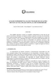
Santiago, A., Simões da Silva L., Vila Real P., Gameiro Lopes A. and Vaz G. (2008),<br />
“Experimental evaluation <strong>of</strong> the influence <strong>of</strong> connection typology on the behaviour<br />
<strong>of</strong> <strong>steel</strong> structures under <strong>fire</strong>”, Engineering Journal, AISC (submitted).<br />
Santiago, A. (2008), “Behaviour <strong>of</strong> <strong>beam</strong>-<strong>to</strong>-<strong>column</strong> <strong>steel</strong> <strong>joints</strong> under natural <strong>fire</strong>”.<br />
Doc<strong>to</strong>ral Thesis, Department <strong>of</strong> Civil Engineering, University <strong>of</strong> Coimbra.<br />
Simões da Silva L., Santiago A. and Vila Real P. (2001), “A component model for<br />
the behaviour <strong>of</strong> <strong>steel</strong> joint at high temperatures”. Journal Constructional<br />
Steel Research, vol. 57(11) (pp. 1169-1195).<br />
Simões da Silva, L., Santiago, A., Vila Real, P. and Moore, D. (2005), ‘Behaviour <strong>of</strong><br />
<strong>steel</strong> <strong>joints</strong> and <strong>fire</strong> loading’. International Journal <strong>of</strong> Steel and Composite<br />
Structures vol. 5(6) (pp. 485-513).<br />
Yin, Y.Z. and Wang, Y.C. (2005), “Analysis <strong>of</strong> catenary action in <strong>steel</strong> <strong>beam</strong>s using a<br />
simplified hand calculation method, Part 1: theory and validation for uniform<br />
temperature distribution”. Journal <strong>of</strong> Constructional Steel Research, vol. 61<br />
(pp. 183-211).