Labsphere RSA-HP-84 Manual
Labsphere RSA-HP-84 Manual
Labsphere RSA-HP-84 Manual

You also want an ePaper? Increase the reach of your titles
YUMPU automatically turns print PDFs into web optimized ePapers that Google loves.
<strong>RSA</strong>-<strong>HP</strong>-<strong>84</strong><br />
I. INTRODUCTION..................................................................................................................1<br />
A. Components.................................................................................................................4<br />
II. INSPECTION PROCEDURE ............................................................................................5<br />
III. INSTALLATION PROCEDURES...................................................................................6<br />
A. Initial Installation .........................................................................................................6<br />
B. Power Connections......................................................................................................6<br />
C. Optical Alignment........................................................................................................7<br />
IV. OPERATING PROCEDURES .........................................................................................9<br />
A. Theory of Operation ....................................................................................................9<br />
B. Diagnostic Scans..........................................................................................................12<br />
C. Hemispherical/8 Degree Reflectance Factor Measurements ........................................14<br />
D. Hemispherical/0° (Specular Excluded) Reflectance Factor Measurements..................15<br />
E. Transmittance Measurement Procedure........................................................................16<br />
V. OPERATING SUGGESTIONS ..........................................................................................17<br />
A. Instrument Parameters..................................................................................................17<br />
B. Zeroline Correction......................................................................................................17<br />
VI. MAINTENANCE................................................................................................................18<br />
A. General Information.....................................................................................................18<br />
B. Mirror Cleaning Procedure ..........................................................................................18<br />
C. Spectralon Care............................................................................................................19<br />
VII. TROUBLE CHECKS........................................................................................................20<br />
A. Electronic Theory of Operation ...................................................................................20<br />
B. Quick Troubleshooting Chart ......................................................................................21<br />
VIII. CUSTOMER SERVICE .................................................................................................22<br />
Artisan Scientific - Quality Instrumentation ... Guaranteed | (888) 88-SOURCE | www.artisan-scientific.com
AQ-00074-000, REV. 3<br />
APPENDIX A ............................................................................................................................23<br />
Technical Notes................................................................................................................23<br />
Definitions........................................................................................................................31<br />
Reflectance.......................................................................................................................31<br />
Transmittance ...................................................................................................................32<br />
APPENDIX B.............................................................................................................................33<br />
Typical Hemispherical/8° Reflectance Factor for SRS-99-010.........................................33<br />
APPENDIX C ............................................................................................................................34<br />
Recommended Reading....................................................................................................34<br />
Artisan Scientific - Quality Instrumentation ... Guaranteed | (888) 88-SOURCE | www.artisan-scientific.com
AQ-00074-000, Rev. 3<br />
Artisan Scientific - Quality Instrumentation ... Guaranteed | (888) 88-SOURCE | www.artisan-scientific.com
I. INTRODUCTION<br />
The <strong>Labsphere</strong> <strong>RSA</strong>-<strong>HP</strong>-<strong>84</strong> is a diffuse reflectance and transmittance accessory designed<br />
exclusively for the Hewlett-Packard <strong>HP</strong><strong>84</strong>52A diode-array spectrophotometer. The<br />
accessory expands the versatility and range of applications for the <strong>HP</strong><strong>84</strong>52A,<br />
accommodating reflectance measurements of both diffuse and specular samples as well as<br />
the transmittance/absorbance of turbid or scattering samples. The integrating sphere<br />
geometry allows for easy measurement of total hemispherical or specular excluded<br />
reflectance.<br />
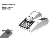
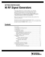
The <strong>RSA</strong>-<strong>HP</strong>-<strong>84</strong> is a modular unit complete with its own power supply, light source,<br />
transfer optics, optical shutter and sample holders in addition to the 95 mm diameter<br />
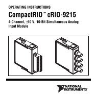
integrating sphere. (See <strong>RSA</strong>-<strong>HP</strong>-<strong>84</strong> illustration, Figure 1. A detail representation of the<br />
<strong>RSA</strong>-<strong>HP</strong>-<strong>84</strong> transfer optics appears in Figure 2.) Easily installed and simple to use, the<br />
<strong>RSA</strong>-<strong>HP</strong>-<strong>84</strong> is compatible with all Hewlett-Packard operating software.<br />
This manual is intended to provide installation procedures for the <strong>RSA</strong>-<strong>HP</strong>-<strong>84</strong> accessory<br />
only. The "Operator's <strong>Manual</strong>" of the Hewlett-Packard <strong>HP</strong><strong>84</strong>52A diode-array<br />
spectrophotometer should be consulted for measurement procedures, since the <strong>RSA</strong>-<strong>HP</strong>-<strong>84</strong><br />
does not modify normal operations.<br />
AQ-00074-000, Rev. 3 1<br />
Artisan Scientific - Quality Instrumentation ... Guaranteed | (888) 88-SOURCE | www.artisan-scientific.com
Shutter<br />
Assembly<br />
Detector<br />
Viewing<br />
Path<br />
Lamp<br />
Integrating<br />
Sphere<br />
Front of <strong>RSA</strong>-<strong>HP</strong>-<strong>84</strong><br />
Figure 1. Top View of the <strong>RSA</strong>-<strong>HP</strong>-<strong>84</strong> Accessory.<br />
Power Supply<br />
Transfer<br />
Optics<br />
Photo Sensor<br />
(Shutter Control)<br />
Transmittance<br />
Port<br />
Dummy<br />
Port<br />
Reflectance<br />
Sample<br />
Port<br />
AQ-00074-000, Rev. 3 2<br />
Artisan Scientific - Quality Instrumentation ... Guaranteed | (888) 88-SOURCE | www.artisan-scientific.com
<strong>RSA</strong>-<strong>HP</strong>-<strong>84</strong><br />
Enclosure<br />
(Transparent<br />
View)<br />
Detector<br />
Viewing<br />
Path<br />
Folding<br />
Mirror 1<br />
Figure 2. Transfer optics detail.<br />
Folding<br />
Mirror 2<br />
Fused<br />
Silica<br />
Lens<br />
Integrating<br />
Sphere<br />
Sample<br />
AQ-00074-000, Rev. 3 3<br />
Artisan Scientific - Quality Instrumentation ... Guaranteed | (888) 88-SOURCE | www.artisan-scientific.com
A. Components<br />
1 <strong>RSA</strong>-<strong>HP</strong>-<strong>84</strong> Reflectance Spectroscopy Accessory (with two mounting screws)<br />
1 8 degree sample holder<br />
1 0 degree transmittance sample holder<br />
2 0 degree reflectance sample holders<br />
1 Power cord<br />
1 SRS-99-010 Calibrated Diffuse Reflectance Standard<br />
1 Calibration certificate(SRS-99)<br />
2 USRS-99-010 Uncalibrated Diffuse Reflectance Standard<br />
1 <strong>RSA</strong>-<strong>HP</strong>-<strong>84</strong> Instruction <strong>Manual</strong><br />
1 Calibration documents (<strong>RSA</strong>-<strong>HP</strong>-<strong>84</strong>)<br />
1 Hex socket driver set<br />
AQ-00074-000, Rev. 3 4<br />
Artisan Scientific - Quality Instrumentation ... Guaranteed | (888) 88-SOURCE | www.artisan-scientific.com
II. INSPECTION PROCEDURE<br />
The Accessory was thoroughly inspected before shipping and should be ready to operate<br />
after completing the set-up instructions. It is packaged and shipped in a reinforced<br />
cardboard carton. Carefully check the assembly after unpacking it for any damage incurred<br />
during shipping. If there is any such damage, file a claim immediately with the involved<br />
carriers and contact <strong>Labsphere</strong>'s Customer Service Department at (603) 927-4266.<br />
AQ-00074-000, Rev. 3 5<br />
Artisan Scientific - Quality Instrumentation ... Guaranteed | (888) 88-SOURCE | www.artisan-scientific.com
III. INSTALLATION PROCEDURES<br />
A. Initial Installation<br />
1. Turn on the <strong>HP</strong><strong>84</strong>52A and enter the <strong>HP</strong> software.<br />
2. Remove the standard cell holder and/or any other accessories from the sample<br />
compartment of the <strong>HP</strong><strong>84</strong>52A.<br />
3. Attach an 8° sample holder to the reflectance (sample) port and a 0° sample holder to<br />
the dummy port, using a 0.35-inch hex wrench.<br />
4. Orient the <strong>RSA</strong>-<strong>HP</strong>-<strong>84</strong> such that the sphere ports are towards the front of the<br />
<strong>HP</strong><strong>84</strong>52A.<br />
5. Lower the accessory into the sample compartment until it rests firmly upon the<br />
mounting studs.<br />
6. Open the top lid of the enclosure.<br />
7. Position the two mounting screws into the holes at the base of the assembly, and<br />
tighten to secure the accessory.<br />
B. Power Connections<br />
1. Locate the AC power connector at the back of the <strong>RSA</strong>-<strong>HP</strong>-<strong>84</strong>.<br />
2. Plug the female end of the power cord into the power input socket of the <strong>RSA</strong>-<strong>HP</strong>-<strong>84</strong>.<br />
3. Plug the male end of the power cord into the electrical outlet.<br />
4. Place an SRS-99-010 calibrated Spectralon (or other) diffuse reflectance standard into<br />
the reflectance (sample) port.<br />
5. Place a USRS-99-010 uncalibrated Spectralon (or other) reflectance standard in the<br />
dummy port.<br />
6. Turn the <strong>RSA</strong>-<strong>HP</strong>-<strong>84</strong> power switch ON. The sphere should illuminate. If the sphere<br />
does not illuminate, recheck all connections.<br />
AQ-00074-000, Rev. 3 6<br />
Artisan Scientific - Quality Instrumentation ... Guaranteed | (888) 88-SOURCE | www.artisan-scientific.com
C. Optical Alignment<br />
The transfer optics of the <strong>RSA</strong>-<strong>HP</strong>-<strong>84</strong> were factory aligned prior to shipping. However,<br />
you should verify the accessory’s alignment before first use to ensure that a misalignment<br />
did not occur in transit.<br />
WARNING: Do not touch mirror or lens surfaces. Skin oil will reduce performance.<br />
Clean gloves are recommended.<br />
1. Make sure that a Spectralon reflectance standard has been placed in both the<br />
reflectance sample and dummy ports.<br />
2. Configure the software parameters as follows: Transmittance mode, Wavelength<br />
Range = 500 - 820 nm.<br />
3. Perform a Blank scan or background correction. The spectrum should appear as a flat<br />
100% transmittance line.<br />
4. Darken the room. This minimizes the ambient light that could reach the accessory.<br />
5. Remove the Spectralon standard from the sample port and put a light trap in its place<br />
or leave the port open.<br />
6. Initiate the sample SCAN, and observe the displayed spectrum. If the accessory is<br />
properly aligned, the open port zeroline scan should appear between 0.2 - 0.4% T.<br />
Otherwise, realignment of the accessory is necessary.<br />
7. If the results appear above 1%, open the top lid of the enclosure to access the mirror<br />
adjustment screws of the transfer optics assembly.<br />
8. Carefully tweak one adjustment screw on the top mirror mount in one direction only.<br />
Initiate the sample SCAN. Rescale the Y-axis as needed.<br />
9. If the displayed scan is lower than the first, continue to tweak the adjustment screw in<br />
that same direction until the transmittance value is minimized. CLEAR the screen<br />
occasionally before continuing to scan.<br />
10. If the displayed scan is higher than the first, tweak the screw in the opposite direction<br />
to obtain the minimum display result.<br />
11. If changes of more than 5% occur during the alignment process, repeat the background<br />
correction of steps 1-3.<br />
12. Repeat the alignment procedure with the remaining adjustment screw on the top mirror<br />
mount to obtain the minimum display result.<br />
13. Using a 7/64"( 5.5 mm) ball end hex driver, tweak each adjustment screw on the<br />
bottom mirror mount as described above until the minimum display result is achieved.<br />
14. Repeat steps 8-13 until the results between the range of 500-820 nm are less that 1%<br />
T; ideally, the result should lie between 0.2 and 0.4% T.<br />
AQ-00074-000, Rev. 3 7<br />
Artisan Scientific - Quality Instrumentation ... Guaranteed | (888) 88-SOURCE | www.artisan-scientific.com
15. Turn on the room lights after the alignment procedure is completed.<br />
Note: Once the accessory is properly aligned, the <strong>HP</strong><strong>84</strong>52A should initialize with the<br />
<strong>RSA</strong>-<strong>HP</strong>-<strong>84</strong> installed in the instrument’s sample compartment. In order to initialize the<br />
instrument properly, the lamp of the <strong>RSA</strong>-<strong>HP</strong>-<strong>84</strong> should be illuminated and the<br />
Spectralon reflectance standards should be positioned over the reflectance sample port<br />
and dummy port before the instrument is turned ON. Upon initialization, the accessory<br />
will make a series of six clicking noises followed by a three second delay and then a<br />
seventh click. At this point, the system is fully initialized and ready for operation.<br />
Note: An error message will appear in the <strong>HP</strong><strong>84</strong>52 display panel (located in the upper<br />
right hand corner of the instrument) until the software has been entered. The message<br />
should disappear once the software and the <strong>RSA</strong>-<strong>HP</strong>-<strong>84</strong> are fully initialized.<br />
AQ-00074-000, Rev. 3 8<br />
Artisan Scientific - Quality Instrumentation ... Guaranteed | (888) 88-SOURCE | www.artisan-scientific.com
IV. OPERATING PROCEDURES<br />
A. Theory of Operation<br />
In a diode array spectrophotometer, the measurement of reflectance factor and transmittance<br />
involves the performance of a blank scan. The blank scan is used to establish a baseline for<br />
the instrument with the sphere in place, much as one would run a baseline with a solvent in<br />
a cuvette in a standard liquid measurement. This correction is performed automatically by<br />
the instrument in the blank scan mode.<br />
The tungsten halogen source within the sphere illuminates the sample with diffuse<br />
radiation. The sample port is imaged onto the polychromator and then to the diode array.<br />
The blank scan records an intensity level for each diode when the reference (which is<br />
placed in the sample port) is measured. When the sample replaces the reference and a<br />
sample scan is performed, the instrument ratios the intensities at each diode with that of the<br />
stored blank. The accessory uses the Hewlett-Packard <strong>84</strong>52's own array. It is assumed that<br />
the detector response is temporally stable while the source--a tungsten halogen lamp--has a<br />
steady, voltage-controlled power supply to ensure lamp stability.<br />
Diode array instruments that employ an integrating sphere as an accessory operate in either<br />
the substitution mode or the comparison mode. That is, a blank scan is run with a sample of<br />
known reflectance positioned in the reflectance sample port during reflectance<br />
measurement, or air is used as the reference during transmittance measurements (or a<br />
cuvette in the transmittance port, if measuring liquids). The dummy port may contain the<br />
sample to be measured (if the comparison mode is used) or a white Spectralon plug<br />
(substitution mode). The flux measured by the detector within the sphere can be expressed<br />
as:<br />
b D = I s ⋅ Rd ⋅ρ r⋅<br />
κ r<br />
Where: Is = light incident into the sphere<br />
Rd = detector response,<br />
ρr = reflectance of reference for background, and<br />
κr = sphere efficiency function<br />
AQ-00074-000, Rev. 3 9<br />
Artisan Scientific - Quality Instrumentation ... Guaranteed | (888) 88-SOURCE | www.artisan-scientific.com
The sphere efficiency factor (κ) for a given sample is a function of many variables<br />
including the spatial distribution of the energy reflected from the sample, the reflectance of<br />
the sphere wall, the geometry of the sphere (location of ports, baffles, etc.) and the<br />
efficiency of the detector itself. However, proper measurement procedures make it possible<br />
to greatly reduce or eliminate the effect of such factors on transmittance and reflectance<br />
factor measurements. Is is dependent on the efficiency of the coupling optics and<br />
polychromator, and the efficiency of the diode array detector itself.<br />
When one measures a sample of different reflectance, the flux measured by the detector can<br />
be expressed as:<br />
s D = I s ⋅ Rd ⋅ s ρ ⋅κ s<br />
Assuming that the spatial distribution of energy reflected from this unknown sample is the<br />
same as that of the original standard, the efficiency factor (κ) will be the same for both<br />
materials:<br />
κr = κs<br />
Therefore,<br />
D<br />
s<br />
D b<br />
I s ⋅ Rd⋅ s<br />
= ρ ⋅ κ s<br />
I s ⋅ Rd ⋅ r ρ ⋅ κ r<br />
and since, Db is set to equal unity, then<br />
ρ<br />
s<br />
s D =<br />
ρ r<br />
Therefore, the value displayed by the instrument (Ds) will simply be equal to the ratio of<br />
the reflectance factor of the unknown sample to that of the original standard. If the<br />
reflectance factor of this original standard is known, it can be used as a reference standard<br />
and the reflectance factor of the unknown sample can be derived as follows:<br />
s ρ = Ds ⋅ r ρ<br />
AQ-00074-000, Rev. 3 10<br />
Artisan Scientific - Quality Instrumentation ... Guaranteed | (888) 88-SOURCE | www.artisan-scientific.com
The foregoing account involves two simplifying assumptions which bear further<br />
discussion. First, the efficiency of the integrating sphere, represented by κs and κr, is not<br />
necessarily constant under changes in the system. The introduction of a reflectance or<br />
transmittance sample into the system may change the sphere efficiency. It is commonly<br />
assumed, however, that both κs and κr will change by the same factor. In a properly<br />
designed integrating sphere, the systematic uncertainty associated with this assumption is<br />
very small. For a diode array instrument, however, κr • κs, except where the reflectances<br />
of reference and sample are very closely matched. Non-matching of sample and reference<br />
reflectance may cause what is called 'single beam substitution error'. This is covered in<br />
some detail in the <strong>Labsphere</strong> publication A Guide to Reflectance Spectroscopy and in<br />
Appendix A. If the comparison method is used, then:<br />
κ = r κ s<br />
and<br />
ρ<br />
ρ<br />
D s = s<br />
and, therefore,<br />
s ρ = Ds∗ρ r<br />
r<br />
exactly as it would in a double beam instrument with chopped, active referencing.<br />
The second assumption applies to reflectance factor measurements. Here it is assumed that<br />
the geometric scattering properties of the sample and the reference standard are identical.<br />
Therefore, the efficiency factor for radiation reflected from each sample will be the same. If<br />
the geometric scattering properties of the sample differ greatly from those of the reference,<br />
significant systematic errors may be introduced into the measurements. Therefore, the<br />
geometric scattering properties of the sample and reference should match as closely as<br />
possible.<br />
AQ-00074-000, Rev. 3 11<br />
Artisan Scientific - Quality Instrumentation ... Guaranteed | (888) 88-SOURCE | www.artisan-scientific.com
B. Diagnostic Scans<br />
A series of diagnostic scans was performed on each accessory at the factory prior to<br />
shipping. The results of the diagnostic scans obtained on your accessory are provided in the<br />
Quality Assurance Document. Upon first installation of this accessory, or if problems with<br />
the accessory are suspected, repeat these diagnostics, as described below and compare the<br />
results with those provided by the factory. Consult <strong>Labsphere</strong>’s Technical Support<br />
Department for help in interpreting these diagnostic scans.<br />
To reproduce these diagnostic scans, first set the parameters in the instrument software to<br />
match those in the "STANDARD CHECKOUT" method, as given below:<br />
• Transmittance<br />
• 360 - 820 nm<br />
• 1 second integration time<br />
• overlay scans<br />
NOTE: When the instrument is turned on with the accessory in place, an error message will<br />
appear stating that there is not enough dark current intensity. Ignore this message.<br />
Energy Scan<br />
1. Set up instrument parameters as in the STANDARD CHECKOUT method described<br />
in the Quality Assurance Document, using intensity as the data mode, rather than<br />
transmittance.<br />
2. Place the calibrated Spectralon standard in the reflectance-sample port. Place the<br />
uncalibrated Spectralon standard in the dummy port.<br />
3. Initiate the scan to record the measurement data. (It is not necessary to record a blank<br />
scan in this case.)<br />
4. Compare the scan with that run in the instrument checkout. While the scans may vary<br />
slightly due to the individual instruments, the shape and intensities of the peaks should<br />
be quite similar. Spikes in the scan are normal. The instrument uses a deuterium lamp<br />
and the accessory uses a tungsten lamp. The instrument corrects scans for the spikes<br />
characteristic of deuterium lamps. When the accessory is used, these correction factors<br />
appear as spikes in the scan.<br />
AQ-00074-000, Rev. 3 12<br />
Artisan Scientific - Quality Instrumentation ... Guaranteed | (888) 88-SOURCE | www.artisan-scientific.com
100% Baseline:<br />
1. Place the calibrated Spectralon reflectance standard in the reflectance sample port and<br />
the uncalibrated standard in the dummy port.<br />
2. Set the instrument parameters to:<br />
Transmittance<br />
360 - 820 nm<br />
Y-scale 95 - 105%T.<br />
3. Perform a blank scan.<br />
4. Without altering the instrument’s configuration, initiate the sample scan to record the<br />
100% baseline scan. The resulting scan should closely resemble that provided in the<br />
documents.<br />
The baseline noise should fall below ±2% from 380 - 820 nm. The noise peaks that appear<br />
below 380 nm are the result of the tungsten lamp which does not produce energy at low<br />
wavelengths. If a quieter scan is required, reset the integration time to between 5 and 10<br />
seconds. This allows the detector to collect more energy for each scan and will reduce the<br />
noise of the spectrum.<br />
Blocked-Beam Zeroline:<br />
1. Collect a blank scan as described in steps 1 - 3 of the 100% baseline procedure.<br />
Change the Y-scale to range from -5 to 5%T.<br />
2. Open the lid of accessory and place a metal plate, or other non-transmitting sample, in<br />
the transmittance sample holder, so that the transmittance-sample port is completely<br />
blocked.<br />
3. Close the accessory lid.<br />
4. Initiate the scan. The resulting spectrum should closely match that provided in the<br />
Q.A. documentation.<br />
Note: Be sure to remove the plate from the beam path when the scan is complete.<br />
Open-Port Zeroline:<br />
1. Remove the Spectralon standard from the dummy port and leave the port open. The<br />
Spectralon standard should remain in position in the reflectance sample port.<br />
2. Turn off the room lights.<br />
3. Scan the blank.<br />
4. Remove the Spectralon standard from the reflectance port. Place the standard into the<br />
dummy port.<br />
5. Initiate the scan with the room darkened. The resulting scan should closely match that<br />
provided in Q.A. documents.<br />
AQ-00074-000, Rev. 3 13<br />
Artisan Scientific - Quality Instrumentation ... Guaranteed | (888) 88-SOURCE | www.artisan-scientific.com
Note: This scan may also be performed with a light trap substituting for the open sample port.<br />
C. Hemispherical/8 Degree Reflectance Factor Measurements<br />
Diffuse Samples - Comparison Method<br />
1. Place the calibrated SRS-99-010 Spectralon standard, or other diffuse reflectance<br />
standard, in the reflectance sample port. Place the sample to be measured in the<br />
dummy port.<br />
2. Scan the blank.<br />
3. Reverse the locations of the standard and the sample.<br />
4. Initiate the scan to record the measurement data.<br />
5. Multiply the values recorded in the resulting scan by the known spectral reflectance<br />
factor values of the diffuse reflectance standard to determine the actual reflectance of<br />
the sample.<br />
6. Repeat this entire procedure for each new sample.<br />
This procedure eliminates single-beam substitution error (see Appendix A).<br />
Diffuse Samples - Substitution Method<br />
While the following substitution method may be used to obtain quick results,<br />
substitution error may be introduced, if the sample to be measured drastically changes<br />
he reflectance properties of the sphere. The substitution method is recommended only<br />
if the reflectance properties of the samples to be measured closely approximate those of<br />
the reference material. If not, errors up to 4% may be expected.<br />
1. Place the calibrated SRS-99-010 Spectralon standard or other diffuse reflectance<br />
standard in the reflectance sample port. Place the uncalibrated USRS-99-010 standard<br />
in the dummy port.<br />
2. Perform a blank scan.<br />
3. Replace the calibrated Spectralon standard in the reflectance sample port with the<br />
sample to be measured.<br />
4. Initiate the scan to record the measurement data.<br />
5. Multiply the values recorded in the resulting scan by the known spectral reflectance<br />
factor values of the reflectance standard to determine the actual reflectance of the<br />
sample.<br />
6. The sample just measured can be replaced with a different sample to obtain further<br />
measurements using the same instrument baseline/blank scan.<br />
Specular Samples<br />
AQ-00074-000, Rev. 3 14<br />
Artisan Scientific - Quality Instrumentation ... Guaranteed | (888) 88-SOURCE | www.artisan-scientific.com
The procedure for specular samples is identical to that described above, except that a<br />
specular reference standard, such as a calibrated first-surface aluminum mirror, is<br />
substituted for the diffuse reflectance standard called for above.<br />
Samples of 'Mixed', or Non-Ideal Reflectance<br />
Many reflectance samples display geometric reflectance distributions which do not conform<br />
closely to either the lambertian distribution of an ideal diffuser or the perfect specular<br />
reflectance of an ideal mirror. For a discussion of approaches to measuring such samples,<br />
see Appendix A.<br />
D. Hemispherical/0 (Specular Excluded) Reflectance Factor<br />
Measurements<br />
The integrating sphere of the accessory has two sample holders for the reflectance sample<br />
port. The standard sample holder is designed to position the sample at an 8° angle. The<br />
second sample holder is designed for normal (0°) incidence. With the 0° sample holder in<br />
place, any specular component of reflection from the sample is excluded, since this<br />
component is directed out of the sphere through the transmittance sample port. Therefore,<br />
the 0° sample holder may be used to make Hemispherical/0° reflectance factor<br />
measurements. The procedure for such measurements is as follows:<br />
1. Remove the 8° sample holder from the reflectance sample port. Install the 0° sample<br />
holder.<br />
2. Follow the measurement procedures in the previous section to determine the diffuse<br />
reflectance of the sample.<br />
NOTE: Measurements performed using the specular excluded geometry should always be<br />
interpreted with caution. A port of finite size is not always effective for the complete exclusion<br />
of a broadened specular peak.<br />
AQ-00074-000, Rev. 3 15<br />
Artisan Scientific - Quality Instrumentation ... Guaranteed | (888) 88-SOURCE | www.artisan-scientific.com
E. Transmittance Measurement Procedure<br />
Non-Scattering Samples - Comparison Method:<br />
1. Place the uncalibrated SRS-99-010 Spectralon standard in the reflectance port and the<br />
sample to be measured in the dummy port, if possible. If a liquid is to be measured, fit<br />
the cuvette and holder in front of the transmittance port. Otherwise, leave the port<br />
empty.<br />
2. Darken the room.<br />
3. Scan the blank.<br />
4. Place the sample to be measured in the transmittance sample holder. Leave the dummy<br />
port open.<br />
5. Initiate the scan and record the measurement data.<br />
6. The value displayed by the instrument is the actual sample transmittance.<br />
Non-Scattering Samples - Substitution Method:<br />
1. Place uncalibrated USRS-99-010 Spectralon reflectance standards in both the<br />
reflectance (sample) and dummy ports. If a liquid is to be measured, fit the cuvette and<br />
holder in front of the transmittance port. Otherwise, leave the port empty.<br />
2. Scan the blank.<br />
3. Place the sample to be measured into the transmittance sample holder.<br />
4. Initiate the scan to record the measurement data.<br />
5. The value displayed by the instrument is the actual sample transmittance.<br />
Scattering Samples:<br />
For transmittance samples exhibiting a high degree of scattering, the procedure described<br />
above does not serve as a measurement of total transmittance. Instead, the result displayed<br />
by the instrument will be an instrument-specific value which is known as regular<br />
transmittance factor. (See definitions, Appendix A.) For this accessory, the regular<br />
transmittance factor of a scattering sample closely approximates the total transmittance of<br />
the sample. For further discussion of the handling of scattering transmittance samples, see<br />
Appendix A.<br />
AQ-00074-000, Rev. 3 16<br />
Artisan Scientific - Quality Instrumentation ... Guaranteed | (888) 88-SOURCE | www.artisan-scientific.com
V. OPERATING SUGGESTIONS<br />
A. Instrument Parameters<br />
Since any integrating sphere accessory acts as an attenuator of signal, run scans at a longer<br />
integration time than in ordinary transmittance work.<br />
B. Zeroline Correction<br />
An integrating sphere is sensitive to small-angle scatter from the sample beam coupling<br />
optics. The scattered radiation strikes the wall of the integrating sphere near the reflectancesample<br />
port, creating a "halo" surrounding the port. This "halo-effect" gives rise to a small<br />
error in measurement of reflectance factor which is most significant when measuring<br />
samples of very low reflectance. Fortunately, this error is relatively easy to characterize and<br />
correct.<br />
The following procedure may be used to correct reflectance factor measurements of diffuse<br />
or specular samples, in either the Hemispherical /8° or Hemispherical /0° geometries:<br />
1. Perform a reflectance-factor measurement of a given sample as described in the<br />
Hemispherical/8 Degree Reflectance Factor Measurements<br />
section.<br />
2. Replace the sample with a light trap (reflectance approximately 0%), and scan to<br />
record measurement data.<br />
3. Compute the corrected reflectance factor for the sample, ρs, as follows:<br />
( ) r<br />
( )<br />
s<br />
R− Z ρ<br />
ρ =<br />
100%− Z<br />
where:<br />
ρr = the reflectance value of the reference standard,<br />
R = the sample data displayed on the instrument and<br />
Z = the data from the light trap measurement.<br />
Note: This zero-correction procedure can also be used in conjunction with a mask at the<br />
reflectance sample port to accurately measure the reflectance factor of samples smaller than the<br />
accessory’s reflectance sample port.<br />
AQ-00074-000, Rev. 3 17<br />
Artisan Scientific - Quality Instrumentation ... Guaranteed | (888) 88-SOURCE | www.artisan-scientific.com
VI. MAINTENANCE<br />
A. General Information<br />
When not in use, the accessory should be stored in a controlled environment. Dust and<br />
moisture may adversely affect its performance.<br />
PRECAUTIONS<br />
o Do not handle mirrors or lenses.<br />
o Do not allow foreign objects to enter the integrating sphere.<br />
o Clean dust and particulate debris out of the sphere using a gentle stream of clean air.<br />
B. Mirror Cleaning Procedure<br />
The mirrors of the transfer optics should never be touched or handled. However, the<br />
mirrors do have a protective magnesium fluoride overcoat to allow cleaning if necessary.<br />
The following procedure is recommended:<br />
1. Spray the mirror with Fantastic Spray Cleaner.<br />
2. Rinse the mirror with distilled water.<br />
3. Repeat until the water sheets off the mirror.<br />
4. Blow dry with a stream of clean nitrogen.<br />
AQ-00074-000, Rev. 3 18<br />
Artisan Scientific - Quality Instrumentation ... Guaranteed | (888) 88-SOURCE | www.artisan-scientific.com
C. Spectralon Care<br />
In order to maintain the unique optical and reflectance properties of Spectralon standards,<br />
keep the surfaces of the material very clean. Should Spectralon become soiled, particles<br />
may be blown off with a jet of clean air. If this is insufficient, sand the piece with 220-240<br />
grit emery cloth under a stream of running water. Sand the surface until it is totally<br />
hydrophobic (water beads and runs off immediately) and then shake off water droplets, or<br />
blow them off with a stream of clean air.<br />
Note: Ordinary compressed-air systems typically carry microscopic oil droplets which may<br />
contaminate Spectralon.<br />
AQ-00074-000, Rev. 3 19<br />
Artisan Scientific - Quality Instrumentation ... Guaranteed | (888) 88-SOURCE | www.artisan-scientific.com
VII. TROUBLE CHECKS<br />
A. Electronic Theory of Operation<br />
The <strong>RSA</strong>-<strong>HP</strong>-<strong>84</strong> Reflectance Spectroscopy Accessory uses the internal lamp of the <strong>HP</strong>-<br />
<strong>84</strong>52 instrument to activate a separate shutter mechanism. This shutter is used to allow the<br />
sample image to be seen by the detector array within the instrument. The shutter within the<br />
accessory is activated by opening the shutter within the instrument by use of a silicon<br />
detector and a driver board.<br />
The shutter driver board works in combination with the shutter in the <strong>HP</strong>-<strong>84</strong>52 instrument.<br />
When the shutter in the instrument opens, the light from the instrument is seen by the<br />
silicon detector mounted to the side of the <strong>RSA</strong>-<strong>HP</strong>-<strong>84</strong> accessory. The signal from the<br />
silicon detector is passed back through a high gain transimpedance amplifier circuit. From<br />
here the resulting voltage is passed through a driver circuit. The driver circuit is comprised<br />
of a voltage detector and a MOSFET driver amplifier. The voltage detector measures for<br />
voltage within a specific range and creates either a HI or LOW depending on the signal.<br />
This is passed along to a drive amplifier which drives a low power MOSFET. The<br />
MOSFET is used as a switch. When a HI is past along to the driver it creates a resulting HI<br />
on the gate of the MOSFET. The MOSFET is part of the load line out to a solenoid that<br />
drives the shutter mechanism. When the MOSFET is turned on, it creates a current path<br />
that allows current to flow to the solenoid. This current engages the solenoid which in turns<br />
activates the shutter in the accessory.<br />
There is a single +12 volt DC power supply used to generate the various bias supplies for<br />
the accessory. The +12 volts is fed to an LM309K +5 volt voltage regulator. The output<br />
voltage from it (+5v) is fed to the lamp connector mounted at the rear of the main<br />
compartment. The lamp is then plugged into it.<br />
AQ-00074-000, Rev. 3 20<br />
Artisan Scientific - Quality Instrumentation ... Guaranteed | (888) 88-SOURCE | www.artisan-scientific.com
B. Quick Troubleshooting Chart<br />
Symptom<br />
Shutter in <strong>RSA</strong>-<strong>HP</strong>-<strong>84</strong> does<br />
not operate.<br />
Accessory lamp does not<br />
come on.<br />
Shutter appears to stick.<br />
Preparation<br />
Remove the accessory from the<br />
<strong>HP</strong>-<strong>84</strong>52. Turn the accessory on<br />
while it is on the bench top. Use a<br />
flashlight to get light to the<br />
detector on the side of the<br />
accessory.<br />
Remove the lamp fixture from the<br />
top of the sphere by loosening the<br />
two recessed set screws within the<br />
base of the fixture where it<br />
attaches to the sphere.<br />
Remove the accessory from the<br />
<strong>HP</strong>-<strong>84</strong>52. Turn the accessory on<br />
while it is on the bench top. Use a<br />
flashlight to get light to the<br />
detector on the side of the<br />
accessory.<br />
Result<br />
If the shutter activates, then the<br />
lamp in the <strong>HP</strong>-<strong>84</strong>52 is low. If it<br />
does not activate there is an<br />
internal problem in the<br />
accessory. Contact <strong>Labsphere</strong><br />
for service.<br />
Visually inspect the lamp for<br />
any breaks either in the glass or<br />
the filament. While wearing<br />
protective gloves, push in and<br />
turn bulb counter-clockwise to<br />
replace bulb, if necessary. To<br />
obtain the correct replacement<br />
bulb, (or if no faults are found<br />
in the lamp) contact <strong>Labsphere</strong>.<br />
If the shutter sticks under test,<br />
gently press against it to reseat<br />
it. If the problem persists contact<br />
<strong>Labsphere</strong> for service.<br />
AQ-00074-000, Rev. 3 21<br />
Artisan Scientific - Quality Instrumentation ... Guaranteed | (888) 88-SOURCE | www.artisan-scientific.com
VIII. CUSTOMER SERVICE<br />
Customer Service is one of <strong>Labsphere</strong>’s most important products! Every <strong>Labsphere</strong> product<br />
includes the finest support and service to assist you in making the most of your state-of-theart<br />
equipment. If you have any questions or comments regarding any of <strong>Labsphere</strong>’s<br />
products, please call:<br />
(603) 927-4266<br />
and ask for the Customer Service Department.<br />
AQ-00074-000, Rev. 3 22<br />
Artisan Scientific - Quality Instrumentation ... Guaranteed | (888) 88-SOURCE | www.artisan-scientific.com
APPENDIX A<br />
Technical Notes<br />
Substitution Error<br />
The substitution error, sometimes referred to as the single beam sample absorption error, is<br />
a systematic, predictable and non-random error inherent in single beam integrating spheres<br />
measuring reflectance or transmittance. The error is caused by the difference between the<br />
throughput of the sphere when the reference makes up a portion of the wall and the<br />
throughput when the sample is substituted for the reference. For reflectance measurements<br />
the throughput is usually lower when the sample is present since a reference material of<br />
high (nearly 100%) reflectance is usually used. For transmittance measurements the<br />
throughput is usually higher when the sample is present since an open port (zero reflectance<br />
when viewed from inside the sphere) is usually used as a reference.<br />
AQ-00074-000, Rev. 3 23<br />
Artisan Scientific - Quality Instrumentation ... Guaranteed | (888) 88-SOURCE | www.artisan-scientific.com
Methods of Correction<br />
When the sample and reference are of similar reflectances the substitution error is<br />
negligible. Even when the sample and reference are not of similar reflectances, at worst, the<br />
substitution error may reach only three or four percent and in many cases it is simple<br />
ignored. In quality control applications where a threshold value is used, the substitution<br />
error can be incorporated into this threshold. For chemical analysis where the locations of<br />
absorption peaks, not necessarily their exact absorbance value, are important the error can<br />
also be ignored. Where correction of the substitution error is necessary, the following<br />
techniques are available.<br />
Double Beam<br />
Instruments which chop between the sample beam and the reference beam have both<br />
beams present in the sphere at essentially the same time. In this case, since the sample beam<br />
and reference beam each "see" the same sphere, there is no substitution error.<br />
Dummy Port<br />
When room permits, single beam spheres can be designed with an additional "dummy"<br />
port. The background correction is performed with the sample to be measured in the<br />
dummy port and the physical reference in the sample port. A sample scan is then run with<br />
the positions of the two switched. In this comparison method the average reflectance (hence<br />
the throughput) of the sphere remains unchanged from the reference scan to the sample<br />
scan. This technique requires that a separate reference scan be run for each sample (unless<br />
the samples are all very similar and the residual substitution error caused by sample-tosample<br />
differences can be ignored).<br />
Matched Sample<br />
If a reference is used which is very close in reflectance to the sample, the substitution error<br />
is negligible.<br />
Low Reflectance or Transmittance<br />
For samples with very low reflectance or transmittance the substitution error will be very<br />
small. For a sample with zero reflectance or transmittance, there is no substitution error at<br />
all. For low reflectance and transmittance samples, the substitution error is so small that it<br />
probably falls within the random noise of the instrument.<br />
AQ-00074-000, Rev. 3 24<br />
Artisan Scientific - Quality Instrumentation ... Guaranteed | (888) 88-SOURCE | www.artisan-scientific.com
Calibrated Standards<br />
For single beam spheres without dummy ports in applications where substitution error is a<br />
concern, the spheres can be calibrated with a set of standards such as one of <strong>Labsphere</strong>'s<br />
Reflectance Standards Sets, which has been measured on a sphere without substitution<br />
error. With these standards, a table of measured vs. actual readings can be generated and<br />
used to correct for substitution error.<br />
The <strong>RSA</strong>-<strong>HP</strong>-<strong>84</strong> is equipped with a dummy port for correcting for substitution error when<br />
desired.<br />
AQ-00074-000, Rev. 3 25<br />
Artisan Scientific - Quality Instrumentation ... Guaranteed | (888) 88-SOURCE | www.artisan-scientific.com
Reflectance Measurement of Non-Ideal Samples<br />
Two simple ideal geometric reflectance distributions may be described: perfect specular<br />
reflection, and perfect diffuse reflection. Perfect specular reflection is simply reflection<br />
according to Fresnel's law, without scattering (or diffusion). Perfect diffuse reflection is<br />
reflection according to Lambert's law, and is therefore described as "lambertian." (See<br />
definitions below.) For the purposes of integrating-sphere-based reflectometry, the<br />
Spectralon standards provided with this accessory serve as an excellent approximation to<br />
the ideal of perfect lambertian reflection, while a clean, flat, first-surface mirror provides an<br />
excellent approximation to the ideal of perfect specular reflection.<br />
If the sample to be measured closely approximates either of these ideal reflectance<br />
distributions, it is not difficult to select an appropriate reference standard. Many samples,<br />
however, do not conform to this requirement. Samples which are neither nearly specular<br />
nor nearly lambertian should, if possible, be measured relative to a standard with similar<br />
geometrical scattering properties. If calibrated standards which meet this criterion are not<br />
available - as is often the case - another approach must be taken.<br />
The first such alternate approach is simply to measure the sample as if it were either nearly<br />
lambertian or nearly specular, and accept that such a measurement involves a higher-than<br />
ordinary degree of systematic uncertainty. Such an approach is more than adequate for<br />
many applications, especially those in which the emphasis is on repeatability, rather than<br />
absolute accuracy of measurement.<br />
A more ambitious approach involves modeling the geometric reflectance distribution of the<br />
sample in question as an ideal "mixed" distribution, composed of two components, one of<br />
which is perfectly specular, and the other, perfectly lambertian. The sample is measured in<br />
both total hemispherical (specular included) and diffuse (specular excluded) geometries,<br />
and the relative magnitude of the two components is estimated from the results. Systematic<br />
errors involved in measuring a partly-specular sample against a diffuse reference, or a<br />
partly-diffuse sample against a specular reference, can then be corrected in accordance with<br />
this model. An example of such an approach is presented below.<br />
AQ-00074-000, Rev. 3 26<br />
Artisan Scientific - Quality Instrumentation ... Guaranteed | (888) 88-SOURCE | www.artisan-scientific.com
Such an approach is most suitable for flat, polished samples with a distinct specular<br />
component. Many samples, however, exhibit a non-ideal “gloss,” i.e., a broadened<br />
specular peak, which is not completely captured by the specular-exclusion light trap. Many<br />
other samples exhibit a diffuse component which does not conform closely to the<br />
lambertian ideal. These deviations from the ideal reduce the accuracy of the correction<br />
prescribed by the ideal model. The accuracy of such correction also depends upon the<br />
efficiency with which the instrument removes the specular component of reflection when in<br />
the specular-excluded configuration.<br />
Example<br />
A first-surface mirror is measured with the instrument in the standard hemispherical<br />
configuration, first using a specular reference standard (M), then using a diffuse reference<br />
standard (M'). The geometric correction factor, γ, is calculated as follows:<br />
1. γ = M/M'<br />
Next, the test sample is measured, using a diffuse reference, in both the standard<br />
hemispherical ('specular included') and diffuse ('specular excluded') configurations. The<br />
results are given as R SIN and R SEX, respectively.<br />
Given the assumption that the geometric reflectance distribution of the test sample can be<br />
separated into two ideal components, one specular (S) and one perfectly lambertian (D),<br />
and further assuming that the reference sample approximates a perfect lambertian<br />
distribution, so that its reflectance factor (ρo) is the same for both specular-included and<br />
specular-excluded geometries, the following relations hold:<br />
2. R SEX = D/ρo<br />
3. R SIN = (S' + D)/ρo<br />
4. D = R SEX * ρo<br />
5. S' = (R SIN - R SEX)ρo<br />
where S' represents the contribution of the specular component of the test sample to the<br />
apparent hemispherical reflectance factor of the sample. This quantity is analogous to the<br />
value M' given in equation (1), and its relation to the actual specular component of<br />
hemispherical reflectance (S) is described in equation (6):<br />
AQ-00074-000, Rev. 3 27<br />
Artisan Scientific - Quality Instrumentation ... Guaranteed | (888) 88-SOURCE | www.artisan-scientific.com
6. S = γS'<br />
7. S = γ(R SIN - R SEX)ρo<br />
On this analysis, the best estimate for the hemispherical/8° reflectance factor of the test<br />
sample (R T), is given as follows:<br />
8. R T = S + D = ( γR SIN + (1-γ)R SEX )ρo<br />
Note that this is not intended as a rigorous treatment of the problems associated with the<br />
measurement of samples of mixed reflectance, but only as an illustration of the sort of<br />
analysis which may be used to reduce some of the systematic errors associated with such<br />
measurements. For a more comprehensive treatment of errors associated with reflectancefactor<br />
measurement, see the references listed at the end of this manual.<br />
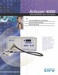
Impinging Light Beam Retroreflection<br />
Diffuse<br />
Reflectance<br />
Specular Reflection<br />
Idealization of Reflectance and Transmittance Phenomena Showing Components*<br />
Measurement of all of the above components except retroreflection may be made using the<br />
<strong>Labsphere</strong> <strong>RSA</strong> accessory. A general technique for each is described below.<br />
* From ASTM E 179-91a<br />
Diffuse<br />
Transmittance<br />
Regular Transmittance<br />
AQ-00074-000, Rev. 3 28<br />
Artisan Scientific - Quality Instrumentation ... Guaranteed | (888) 88-SOURCE | www.artisan-scientific.com
Transmittance Measurement of Scattering Samples<br />
For scattering samples, there are three primary types of transmittance measurement: These<br />
are measurements of total transmittance, diffuse transmittance, and regular transmittance.<br />
All measurements are taken after a background correction (blank) scan of the instrument<br />
has been taken. The background correction calculates the amount of incident light entering<br />
the sphere; it should be taken with Spectralon standards in both the sample and dummy<br />
ports and with a sample cuvette (if used) fitted in front of the transmittance port. (See<br />
DEFINITIONS below.)<br />
Measurement of Total Transmittance (Tt):<br />
To measure the total transmittance of a sample, the sample scan is performed with the<br />
sample to be measured fitted in front of the transmittance port, and Spectralon standards are<br />
placed in both the sample and dummy ports.<br />
Measurement of Diffuse Transmittance (Td):<br />
Diffuse transmittance, which measures the amount of light that is scattered after passing<br />
through a sample, can be determined by performing the sample scan with the sample to be<br />
measured in the transmittance port, a Spectralon standard in the dummy port, and a light<br />
trap* in the sample port. The light trap is located across from the transmittance/entrance<br />
port so that the directly transmitted portion of the sample spectrum is eliminated from the<br />
results.<br />
Determination of Regular Transmittance (Tr):<br />
Regular transmittance can be calculated using the numerical results of the first two scans.<br />
Regular transmittance is the part of the incident light that is transmitted without scattering.<br />
The total transmittance minus the diffuse transmittance equals the regular transmittance<br />
component of the sample spectrum.<br />
Tr = Tt - Td<br />
*Instead of using a light trap during diffuse transmittance scans on the <strong>RSA</strong>-<strong>HP</strong>-<strong>84</strong><br />
accessories, the sample port can be left open (empty). The open sample port will effectively<br />
serve as a light trap, with transmittance only slightly greater than zero. If an open port scan<br />
is performed, the room must be darkened so that external light does not enter the sphere and<br />
interfere with the transmittance measurements.<br />
Note: The regular transmittance factor, as defined by the ASTM, should not be confused with<br />
regular transmittance. (See DEFINITIONS below.) Regular transmittance is a real property<br />
of the sample, which may be more or less accurately measured by different instruments.<br />
AQ-00074-000, Rev. 3 29<br />
Artisan Scientific - Quality Instrumentation ... Guaranteed | (888) 88-SOURCE | www.artisan-scientific.com
Regular transmittance factor, on the other hand, is an instrument-specific quantity, not merely<br />
in practice, but by definition.<br />
AQ-00074-000, Rev. 3 30<br />
Artisan Scientific - Quality Instrumentation ... Guaranteed | (888) 88-SOURCE | www.artisan-scientific.com
Definitions<br />
The following definitions are given in ASTM Standard E-2<strong>84</strong>-90:<br />
diffusion: change of the angular distribution of a beam of radiant flux by a transmitting<br />
material or a reflecting surface such that flux incident in one direction is continuously<br />
distributed in many directions, the process not conforming (on a macroscopic scale) to the<br />
laws of Fresnel (regular) reflection and refraction and there being no change in frequency<br />
(wavelength) of the monochromatic components of the flux.<br />
Lambertian diffuser: ideal surface that reflects or transmits radiation completely in accord<br />
with Lambert's cosine law. When illuminated from any direction, its radiance is the same<br />
for every direction of view.<br />
Lambert's law: the intensity (flux per unit solid angle) emitted in any direction from a<br />
surface varies as the cosine of the angle between the normal to the surface and the direction<br />
of the emitted flux (also called Lambert's cosine law).<br />
Reflectance<br />
reflectance: ratio of the reflected radiant or luminous flux to the incident flux in the given<br />
conditions.<br />
Discussion - The term reflectance is often used in a general sense or as an abbreviation for<br />
reflectance factor. Such usage may be assumed unless the above definition is specifically<br />
required by the context.<br />
reflectance factor: ratio of the flux reflected from the specimen to the flux reflected from<br />
the perfect reflecting diffuser under the same geometric and spectral conditions of<br />
measurement.<br />
diffuse reflection: reflection in which flux is scattered in many directions by diffusion at or<br />
below the surface.<br />
specular reflection: reflection without diffusion, in accordance with the laws of optical<br />
reflection, as in a mirror.<br />
mixed reflection: partly specular and partly diffuse reflection.<br />
AQ-00074-000, Rev. 3 31<br />
Artisan Scientific - Quality Instrumentation ... Guaranteed | (888) 88-SOURCE | www.artisan-scientific.com
perfect reflecting diffuser: ideal reflecting surface that neither absorbs nor transmits light,<br />
but reflects diffusely, with the radiance of the reflecting surface being the same for all<br />
reflecting angles, regardless of the angular distribution of the incident light.<br />
Transmittance<br />
transmittance: the ratio of transmitted flux to incident flux, under specified geometric and<br />
spectral conditions.<br />
transmittance factor : ratio of the flux transmitted by the specimen to the flux transmitted<br />
by the perfect transmitting diffuser under the same geometric and spectral conditions of<br />
measurement.<br />
regular transmittance : ratio of undiffused transmitted flux to incident flux.<br />
diffuse transmittance: ratio of the flux transmitted by a specimen to the incident flux, the<br />
transmitted flux being measured for all forward angles except the regular transmittance<br />
angle.<br />
total transmittance: the ratio of the flux transmitted at all forward angles to the incident<br />
flux.<br />
* regular transmittance factor: the ratio of the flux transmitted by a specimen and<br />
evaluated by a receiver to the flux passing through the same optical system and evaluated<br />
by the receiver when the specimen is removed from the system.<br />
Discussion-In some cases, this quantity is practically identical to the transmittance, but it<br />
may differ considerably. It exceeds unity if the system is such that the specimen causes<br />
more light to reach the receiver than would in its absence.<br />
mixed transmission: a combination of diffuse and regular transmission.<br />
perfect transmitting diffuser: ideal transmitting specimen that neither absorbs nor reflects<br />
light, but transmits diffusely, with the radiance of the specimen being the same for all<br />
transmitting angles, regardless of the angular distribution of the incident light.<br />
AQ-00074-000, Rev. 3 32<br />
Artisan Scientific - Quality Instrumentation ... Guaranteed | (888) 88-SOURCE | www.artisan-scientific.com
APPENDIX B<br />
Typical Hemispherical/8° Reflectance Factor for SRS-99-010<br />
Wavelength (nm) Reflectance<br />
400 0.991<br />
500 0.991<br />
600 0.992<br />
700 0.992<br />
800 0.991<br />
900 0.991<br />
1000 0.992<br />
1100 0.992<br />
AQ-00074-000, Rev. 3 33<br />
Artisan Scientific - Quality Instrumentation ... Guaranteed | (888) 88-SOURCE | www.artisan-scientific.com
APPENDIX C<br />
Recommended Reading<br />
Reference Materials for Diffuse Reflectance<br />
Brunsting, A., R. S. Hernaiz and A. J. Dossman, ‘‘Small Area Measurements of Diffuse<br />
Reflectance from 410 nm to 700 nm’’, Applied Optics, Vol. 23, No. 23, 19<strong>84</strong>.<br />
Budde, W. "Calibration of Reflectance Standards", Journal of Research of the NBS, 80A<br />
(4), 585-595, 1976.<br />
Erb, W. and W. Budde, "Properties of Standard Materials for Reflection", Color Research<br />
and Application, 4 (3), 113-118, 1979.<br />
Hunter, R. S. and R. W. Harold, ‘‘The Measurement of Appearance’’, Wiley Interscience,<br />
1987.<br />
Kortum, G. ‘‘Reflectance Spectroscopy’’, Springer-Verlag, 1969.<br />
Springsteen, A. W., "A Guide to Reflectance Spectroscopy," <strong>Labsphere</strong> Technical Guide ,<br />
1992.<br />
Springsteen, A. W., Leland, J. E., Ricker, T. M. " A Guide to Reflectance Materials and<br />
Coatings" <strong>Labsphere</strong> Technical Guide, 1994.<br />
Weidner V .R. and J. J. Hsia. "Reflectance Properties of Pressed Polytetrafluoroethylene<br />
Powders," J.O.S.A., 71(7) 856-861, 1981.<br />
Weidner, V. R. and J. J. Hsia, ‘‘Spectral Reflectance’’, NBS Publication SP-250-8, July<br />
1987.<br />
Weidner, V. R., J. J Hsia and B. Adams, ‘‘Laboratory Intercomparison Study of Pressed<br />
Polytetrafluoroethylene Powder Reflectance Standards’’, Applied Optics, Vol. 24,<br />
No. 14, July 1986.<br />
AQ-00074-000, Rev. 3 34<br />
Artisan Scientific - Quality Instrumentation ... Guaranteed | (888) 88-SOURCE | www.artisan-scientific.com
Errors in Reflectance Measurements<br />
Clarke, F. J. J. and J. A. Compton, "Correction Methods for Integrating Sphere<br />
Measurements of Hemispherical Reflectance", Color Research and Application, 11<br />
(4), 253-262, 1986.<br />
Goebel, D. G., "Generalized Integrating Sphere Theory", Applied Optics, 6 (1), 125-128,<br />
1967.<br />
Roos, A., C. G. Ribbing and M. Bergkvist, "Anomalies in Integrating Sphere<br />
Measurements on Structured Samples", Applied Optics, 27 (18), 3828-3832, 1988.<br />
Zwinkels, J. C., "Errors in Colorimetry Caused by the Measuring Instrument", Textile<br />
Chemist and Colorist, 21 (2), 23-29, 1989.<br />
AQ-00074-000, Rev. 3 35<br />
Artisan Scientific - Quality Instrumentation ... Guaranteed | (888) 88-SOURCE | www.artisan-scientific.com