Tira vibration test systems - Swissvacuum.com
Tira vibration test systems - Swissvacuum.com
Tira vibration test systems - Swissvacuum.com
You also want an ePaper? Increase the reach of your titles
YUMPU automatically turns print PDFs into web optimized ePapers that Google loves.
How Does an Exciter Work?<br />
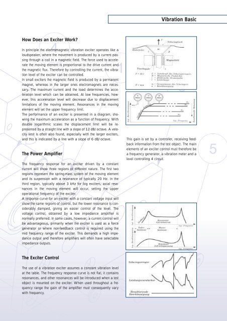
In principle the electromagnetic <strong>vibration</strong> exciter operates like a<br />
loudspeaker, where the movement is produced by a current passing<br />
through a coil in a magnetic field. The force used to accelerate<br />
the moving element is proportional to the drive current and<br />
the magnetic flux. Therefore by controlling the current, the <strong>vibration</strong><br />
level of the exciter can be controlled.<br />
In small exciters the magnetic field is produced by a permanent<br />
magnet, whereas in the larger ones electromagnets are necessary.<br />
The maximum current and the load determines the acceleration<br />
level which can be obtained. At low frequencies, however,<br />
this acceleration level will decrease due to displacement<br />
limitations of the moving element. Resonances in the moving<br />
element will set the upper frequency limit.<br />
The performance of an exciter is presented in a diagram, showing<br />
the maximum acceleration as a function of frequency. With<br />
double logarithmic scales the displacement limit will be represented<br />
by a straight line with a slope of 12 dB/octave. A velocity<br />
limit is often also found, especially with the larger exciters,<br />
and this is indicated by a line with a slope of 6 dB/octave.<br />
The Power Amplifier<br />
The frequency response for an exciter driven by a constant<br />
current will show three regions of different nature. The first two<br />
regions represent the spring-mass system of the moving element<br />
and its suspension with a resonance of typically 20 Hz. In the<br />
third region, typically above 3 kHz for big exciters, axial resonances<br />
in the moving element will occur, setting the upper<br />
operational frequency of the exciter.<br />
A response curve for an exciter with a constant voltage input will<br />
show the same regions of control, but the lower resonance is considerably<br />
damped, giving an easier control of the level. The<br />
voltage control, obtained by a low impedance amplifier is<br />
normally preferred. In some cases, however, a current control will<br />
be advantageous, primarily when the exciter is used as a force<br />
generator or where non-feedback control is required using the<br />
mid frequency range of the exciter. This demands a high impedance<br />
output and therefore amplifiers will often have selectable<br />
impedance outputs.<br />
The Exciter Control<br />
The use of a <strong>vibration</strong> exciter assumes a constant <strong>vibration</strong> level<br />
at the table. The frequency response curve is not flat, it contains<br />
resonances, and other resonances will be introduced when a <strong>test</strong><br />
object is mounted on the exciter. When used throughout a frequency<br />
range the gain of the amplifier must consequently vary<br />
with frequency.<br />
Vibration Basic<br />
This gain is set by a controller, receiving feedback<br />
information from the <strong>test</strong> object. The main<br />
elements of an exciter control must therefore be<br />
a frequency generator, a <strong>vibration</strong> meter and a<br />
level controlling 4 circuit.


