GAL16V8 Data Sheet - der HTL Steyr
GAL16V8 Data Sheet - der HTL Steyr
GAL16V8 Data Sheet - der HTL Steyr

Create successful ePaper yourself
Turn your PDF publications into a flip-book with our unique Google optimized e-Paper software.
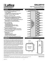
POWER-UP RESET<br />
Circuitry within the <strong>GAL16V8</strong> provides a reset signal to all registers<br />
during power-up. All internal registers will have their Q<br />
outputs set low after a specified time (tpr, 1μs MAX). As a result,<br />
the state on the registered output pins (if they are enabled) will<br />
always be high on power-up, regardless of the programmed<br />
polarity of the output pins. This feature can greatly simplify state<br />
machine design by providing a known state on power-up. Because<br />
of the asynchronous nature of system power-up, some<br />
INPUT/OUTPUT EQUIVALENT SCHEMATICS<br />
PIN<br />
PIN<br />
Typ. Vref = 3.2V<br />
Vcc Vref<br />
ESD<br />
Protection<br />
Circuit<br />
ESD<br />
Protection<br />
Circuit<br />
Active Pull-up<br />
Circuit<br />
Typical Input<br />
Vcc<br />
CLK<br />
INTERNAL REGISTER<br />
Q - OUTPUT<br />
FEEDBACK/EXTERNAL<br />
OUTPUT REGISTER<br />
Vcc<br />
Vcc (min.)<br />
Vcc<br />
tpr<br />
20<br />
twl<br />
<strong>Data</strong><br />
Output<br />
Typ. Vref = 3.2V<br />
Specifications <strong>GAL16V8</strong><br />
tsu<br />
Internal Register<br />
Reset to Logic "0"<br />
Device Pin<br />
Reset to Logic "1"<br />
conditions must be met to provide a valid power-up reset of the<br />
device. First, the VCC rise must be monotonic. Second, the clock<br />
input must be at static TTL level as shown in the diagram during<br />
power up. The registers will reset within a maximum of tpr time.<br />
As in normal system operation, avoid clocking the device until all<br />
input and feedback path setup times have been met. The clock<br />
must also meet the minimum pulse width requirements.<br />
Feedback<br />
Tri-State<br />
Control<br />
Vcc<br />
Typical Output<br />
Active Pull-up<br />
Circuit<br />
Vref<br />
Feedback<br />
(To Input Buffer)<br />
PIN<br />
PIN