GAL22V10
GAL22V10
GAL22V10

You also want an ePaper? Increase the reach of your titles
YUMPU automatically turns print PDFs into web optimized ePapers that Google loves.
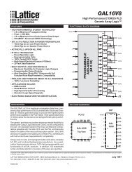
FEATURES<br />
• HIGH PERFORMANCE E2CMOS ® TECHNOLOGY<br />
— 5 ns Maximum Propagation Delay<br />
— Fmax = 200 MHz<br />
— 4 ns Maximum from Clock Input to Data Output<br />
— UltraMOS ® Advanced CMOS Technology<br />
• ACTIVE PULL-UPS ON ALL PINS<br />
• COMPATIBLE WITH STANDARD 22V10 DEVICES<br />
— Fully Function/Fuse-Map/Parametric Compatible<br />
with Bipolar and UVCMOS 22V10 Devices<br />
• 50% to 75% REDUCTION IN POWER VERSUS BIPOLAR<br />
— 90mA Typical Icc on Low Power Device<br />
— 45mA Typical Icc on Quarter Power Device<br />
•E2 CELL TECHNOLOGY<br />
— Reconfigurable Logic<br />
— Reprogrammable Cells<br />
— 100% Tested/Guaranteed 100% Yields<br />
— High Speed Electrical Erasure (
<strong>GAL22V10</strong> ORDERING INFORMATION<br />
Commercial Grade Specifications<br />
T pd<br />
( ns)<br />
T su<br />
( ns)<br />
T co<br />
( ns)<br />
I cc<br />
( mA)<br />
Ordering #<br />
Package<br />
5 3 4 150 <strong>GAL22V10</strong>C-5LJ 28-Lead<br />
PLCC<br />
7. 5 5 4. 5 140 <strong>GAL22V10</strong>C-7LP 24-Pin<br />
Plastic<br />
DIP<br />
4. 5 4. 5 140 <strong>GAL22V10</strong>C-7LJ 28-Lead<br />
PLCC<br />
6. 5 5 140 <strong>GAL22V10</strong>B-7LP 24-Pin<br />
Plastic<br />
DIP<br />
140 <strong>GAL22V10</strong>B-7LJ 28-Lead<br />
PLCC<br />
10 7 7 130 <strong>GAL22V10</strong>C-10LP 24-Pin<br />
Plastic<br />
DIP<br />
130 <strong>GAL22V10</strong>C-10LJ 28-Lead<br />
PLCC<br />
130 <strong>GAL22V10</strong>B-10LP 24-Pin<br />
Plastic<br />
DIP<br />
130 <strong>GAL22V10</strong>B-10LJ 28-Lead<br />
PLCC<br />
15 10 8 55 <strong>GAL22V10</strong>B-15QP 24-Pin<br />
Plastic<br />
DIP<br />
55 <strong>GAL22V10</strong>B-15QJ 28-Lead<br />
PLCC<br />
130 <strong>GAL22V10</strong>B-15LP 24-Pin<br />
Plastic<br />
DIP<br />
130 <strong>GAL22V10</strong>B-15LJ 28-Lead<br />
PLCC<br />
25 15 15 55 <strong>GAL22V10</strong>B-25QP 24-Pin<br />
Plastic<br />
DIP<br />
55 <strong>GAL22V10</strong>B-25QJ 28-Lead<br />
PLCC<br />
90 <strong>GAL22V10</strong>B-25LP 24-Pin<br />
Plastic<br />
DIP<br />
90 <strong>GAL22V10</strong>B-25LJ 28-Lead<br />
PLCC<br />
Industrial Grade Specifications<br />
T pd<br />
( ns)<br />
T su<br />
( ns)<br />
T co<br />
( ns)<br />
I cc<br />
( mA)<br />
Ordering #<br />
Package<br />
7. 5 5 4. 5 160 <strong>GAL22V10</strong>C-7LPI 24-Pin<br />
Plastic<br />
DIP<br />
4. 5 4. 5 160 <strong>GAL22V10</strong>C-7LJI 28-Lead<br />
PLCC<br />
10 7 7 160 <strong>GAL22V10</strong>C-10LPI 24-Pin<br />
Plastic<br />
DIP<br />
160 <strong>GAL22V10</strong>C-10LJI 28-Lead<br />
PLCC<br />
15 10 8 150 <strong>GAL22V10</strong>B-15LPI 24-Pin<br />
Plastic<br />
DIP<br />
150 <strong>GAL22V10</strong>B-15LJI 28-Lead<br />
PLCC<br />
20 14 10 150 <strong>GAL22V10</strong>B-20LPI 24-Pin<br />
Plastic<br />
DIP<br />
150 <strong>GAL22V10</strong>B-20LJI 28-Lead<br />
PLCC<br />
25 15 15 150 <strong>GAL22V10</strong>B-25LPI 24-Pin<br />
Plastic<br />
DIP<br />
150 <strong>GAL22V10</strong>B-25LJI 28-Lead<br />
PLCC<br />
PART NUMBER DESCRIPTION<br />
<strong>GAL22V10</strong>C<br />
<strong>GAL22V10</strong>B<br />
L = Low Power<br />
Q = Quarter Power<br />
Device Name<br />
Speed (ns)<br />
Power<br />
XXXXXXXX<br />
_<br />
XX X X X<br />
Specifications <strong>GAL22V10</strong><br />
Grade<br />
Package<br />
Blank = Commercial<br />
I = Industrial<br />
P = Plastic DIP<br />
J = PLCC<br />
2 1996 Data Book
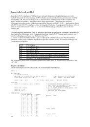
OUTPUT LOGIC MACROCELL (OLMC)<br />
The <strong>GAL22V10</strong> has a variable number of product terms per<br />
OLMC. Of the ten available OLMCs, two OLMCs have access to<br />
eight product terms (pins 14 and 23, DIP pinout), two have ten<br />
product terms (pins 15 and 22), two have twelve product terms<br />
(pins 16 and 21), two have fourteen product terms (pins 17 and<br />
20), and two OLMCs have sixteen product terms (pins 18 and 19).<br />
In addition to the product terms available for logic, each OLMC<br />
has an additional product-term dedicated to output enable control.<br />
The output polarity of each OLMC can be individually programmed<br />
to be true or inverting, in either combinatorial or registered mode.<br />
This allows each output to be individually configured as either<br />
active high or active low.<br />
CLK<br />
<strong>GAL22V10</strong> OUTPUT LOGIC MACROCELL (OLMC)<br />
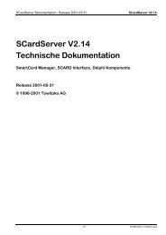
OUTPUT LOGIC MACROCELL CONFIGURATIONS<br />
Each of the Macrocells of the <strong>GAL22V10</strong> has two primary functional<br />
modes: registered, and combinatorial I/O. The modes and<br />
the output polarity are set by two bits (SO and S1), which are normally<br />
controlled by the logic compiler. Each of these two primary<br />
modes, and the bit settings required to enable them, are described<br />
below and on the following page.<br />
REGISTERED<br />
In registered mode the output pin associated with an individual<br />
OLMC is driven by the Q output of that OLMC’s D-type flip-flop.<br />
Logic polarity of the output signal at the pin may be selected by<br />
specifying that the output buffer drive either true (active high) or<br />
inverted (active low). Output tri-state control is available as an individual<br />
product-term for each OLMC, and can therefore be defined<br />
by a logic equation. The D flip-flop’s /Q output is fed back<br />
into the AND array, with both the true and complement of the<br />
feedback available as inputs to the AND array.<br />
D<br />
2 TO 1<br />
MUX<br />
AR<br />
SP<br />
Q<br />
Q<br />
Specifications <strong>GAL22V10</strong><br />
The <strong>GAL22V10</strong> has a product term for Asynchronous Reset (AR)<br />
and a product term for Synchronous Preset (SP). These two<br />
product terms are common to all registered OLMCs. The Asynchronous<br />
Reset sets all registers to zero any time this dedicated<br />
product term is asserted. The Synchronous Preset sets all registers<br />
to a logic one on the rising edge of the next clock pulse after<br />
this product term is asserted.<br />
NOTE: The AR and SP product terms will force the Q output of<br />
the flip-flop into the same state regardless of the polarity of the<br />
output. Therefore, a reset operation, which sets the register output<br />
to a zero, may result in either a high or low at the output pin,<br />
depending on the pin polarity chosen.<br />
4 TO 1<br />
MUX<br />
NOTE: In registered mode, the feedback is from the /Q output of<br />
the register, and not from the pin; therefore, a pin defined as<br />
registered is an output only, and cannot be used for dynamic<br />
I/O, as can the combinatorial pins.<br />
COMBINATORIAL I/O<br />
In combinatorial mode the pin associated with an individual OLMC<br />
is driven by the output of the sum term gate. Logic polarity of the<br />
output signal at the pin may be selected by specifying that the<br />
output buffer drive either true (active high) or inverted (active low).<br />
Output tri-state control is available as an individual product-term<br />
for each output, and may be individually set by the compiler as<br />
either “on” (dedicated output), “off” (dedicated input), or “productterm<br />
driven” (dynamic I/O). Feedback into the AND array is from<br />
the pin side of the output enable buffer. Both polarities (true and<br />
inverted) of the pin are fed back into the AND array.<br />
3 1996 Data Book
REGISTERED MODE<br />
S 0 = 0<br />
S 1 = 0<br />
ACTIVE LOW<br />
COMBINATORIAL MODE<br />
S 0 = 0<br />
S 1 = 1<br />
CLK<br />
AR<br />
D Q<br />
SP<br />
ACTIVE LOW<br />
Q<br />
S 0 = 1<br />
S 1 = 0<br />
S 0 = 1<br />
S 1 = 1<br />
Specifications <strong>GAL22V10</strong><br />
CLK<br />
ACTIVE HIGH<br />
ACTIVE HIGH<br />
4 1996 Data Book<br />
AR<br />
D Q<br />
SP<br />
Q
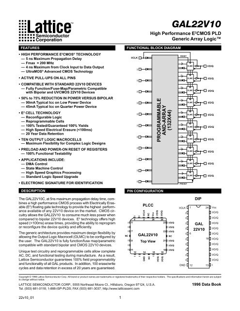
<strong>GAL22V10</strong> LOGIC DIAGRAM / JEDEC FUSE MAP<br />
1 (2)<br />
2 (3)<br />
3 (4)<br />
4 (5)<br />
5 (6)<br />
6 (7)<br />
7 (9)<br />
8 (10)<br />
9 (11)<br />
10 (12)<br />
0000<br />
0044<br />
.<br />
.<br />
.<br />
0396<br />
0440<br />
.<br />
.<br />
.<br />
.<br />
0880<br />
0924<br />
.<br />
.<br />
.<br />
.<br />
.<br />
1452<br />
1496<br />
.<br />
.<br />
.<br />
.<br />
.<br />
.<br />
2112<br />
2156<br />
.<br />
.<br />
.<br />
.<br />
.<br />
.<br />
.<br />
2860<br />
2904<br />
.<br />
.<br />
.<br />
.<br />
.<br />
.<br />
.<br />
3608<br />
3652<br />
.<br />
.<br />
.<br />
.<br />
.<br />
.<br />
4268<br />
4312<br />
.<br />
.<br />
.<br />
.<br />
.<br />
4840<br />
4884<br />
.<br />
.<br />
.<br />
.<br />
5324<br />
5368<br />
.<br />
.<br />
.<br />
5720<br />
5764<br />
DIP (PLCC) Package Pinouts<br />
0 4 8 12 16 20 24 28 32 36 40<br />
Specifications <strong>GAL22V10</strong><br />
ASYNCHRONOUS RESET<br />
(TO ALL REGISTERS)<br />
S0<br />
5808<br />
S1<br />
5809<br />
OLMC<br />
S0<br />
5810<br />
S1<br />
5811<br />
OLMC<br />
S0<br />
5812<br />
S1<br />
5813<br />
OLMC<br />
S0<br />
5814<br />
S1<br />
5815<br />
OLMC<br />
S0<br />
5816<br />
S1<br />
5817<br />
OLMC<br />
S0<br />
5818<br />
S1<br />
5819<br />
OLMC<br />
S0<br />
5820<br />
S1<br />
5821<br />
OLMC<br />
S0<br />
5822<br />
S1<br />
5823<br />
OLMC<br />
S0<br />
5824<br />
S1<br />
5825<br />
OLMC<br />
S0<br />
5826<br />
S1<br />
5827<br />
SYNCHRONOUS PRESET<br />
(TO ALL REGISTERS)<br />
23 (27)<br />
22 (26)<br />
21 (25)<br />
20 (24)<br />
19 (23)<br />
18 (21)<br />
17 (20)<br />
16 (19)<br />
15 (18)<br />
14 (17)<br />
11 (13) 13 (16)<br />
5828, 5829 ... Electronic Signature ... 5890, 5891<br />
Byte 7 Byte 6 Byte 5 Byte 4 Byte 3<br />
Byte 2 Byte 1 Byte 0<br />
M SB<br />
L<br />
S<br />
B<br />
8 OLMC<br />
10<br />
12<br />
14<br />
16<br />
16<br />
14<br />
12<br />
10<br />
8<br />
5 1996 Data Book
ABSOLUTE MAXIMUM RATINGS (1)<br />
Supply voltage V ....................................... -0.5 to +7V<br />
CC<br />
Input voltage applied ........................... -2.5 to V +1.0V<br />
CC<br />
Off-state output voltage applied........... -2.5 to V +1.0V<br />
CC<br />
Storage Temperature.................................. -65 to 150°C<br />
Ambient Temperature with<br />
Power Applied ......................................... -55 to 125°C<br />
1. Stresses above those listed under the “Absolute Maximum<br />
Ratings” may cause permanent damage to the device. These<br />
are stress only ratings and functional operation of the device<br />
at these or at any other conditions above those indicated in<br />
the operational sections of this specification is not implied<br />
(while programming, follow the programming specifications).<br />
DC ELECTRICAL CHARACTERISTICS<br />
COMMERCIAL<br />
Specifications <strong>GAL22V10</strong>C<br />
<strong>GAL22V10</strong><br />
RECOMMENDED OPERATING COND.<br />
Commercial Devices:<br />
Ambient Temperature (T A ) ............................. 0 to +75°C<br />
Supply voltage (V CC )<br />
with Respect to Ground ..................... +4.75 to +5.25V<br />
Industrial Devices:<br />
Ambient Temperature (T A ) ............................ -40 to 85°C<br />
Supply voltage (V CC )<br />
with Respect to Ground ..................... +4.50 to +5.50V<br />
Over Recommended Operating Conditions (Unless Otherwise Specified)<br />
SYMBOL PARAMETER CONDITION MIN. TYP. 3 MAX. UNITS<br />
VIL Input Low Voltage Vss – 0.5 — 0.8 V<br />
VIH Input High Voltage 2.0 — Vcc+1 V<br />
IIL 1 Input or I/O Low Leakage Current 0V ≤ VIN ≤ VIL (MAX.) — — –100 μA<br />
IIH Input or I/O High Leakage Current 3.5V ≤ VIN ≤ VCC — — 10 μA<br />
VOL Output Low Voltage IOL = MAX. Vin = VIL or VIH — — 0.5 V<br />
VOH Output High Voltage IOH = MAX. Vin = VIL or VIH 2.4 — — V<br />
IOL Low Level Output Current — — 16 mA<br />
IOH High Level Output Current — — –3.2 mA<br />
IOS 2 Output Short Circuit Current VCC = 5V VOUT = 0.5V T A = 25°C –30 — –130 mA<br />
ICC Operating Power Supply Current VIL = 0.5V VIH = 3.0V L-5 — 90 150 mA<br />
ftoggle = 15MHz Outputs Open L-7 — 90 140 mA<br />
L-10 — 90 130 mA<br />
INDUSTRIAL<br />
ICC Operating Power Supply Current VIL = 0.5V VIH = 3.0V<br />
ftoggle = 15MHz Outputs Open<br />
L-7/-10 — 90 160 mA<br />
1) The leakage current is due to the internal pull-up on all pins. See Input Buffer section for more information.<br />
2) One output at a time for a maximum duration of one second. Vout = 0.5V was selected to avoid test problems caused by tester<br />
ground degradation. Guaranteed but not 100% tested.<br />
3) Typical values are at Vcc = 5V and TA = 25 °C<br />
6 1996 Data Book
AC SWITCHING CHARACTERISTICS<br />
Over Recommended Operating Conditions<br />
Specifications <strong>GAL22V10</strong>C<br />
<strong>GAL22V10</strong><br />
PARAM UNITS<br />
TEST<br />
COND. 1 DESCRIPTION<br />
-5 -7 (PLCC) -7 (PDIP) -10 -10<br />
MIN. MAX. MIN. MAX. MIN. MAX. MIN. MAX. MIN. MAX.<br />
tpd A Input or I/O to Combinatorial Output 1 5 1 7.5 1 7.5 3 10 1 10 ns<br />
tco A Clock to Output Delay 1 4 1 4.5 1 4.5 2 7 1 7 ns<br />
tcf 2 — Clock to Feedback Delay — 3 — 3 — 3 — 2.5 — 2.5 ns<br />
tsu — Setup Time, Input or Fdbk before Clk↑ 3 — 4.5 — 5 — 7 — 7 — ns<br />
th — Hold Time, Input or Fdbk after Clk↑ 0 — 0 — 0 — 0 — 0 — ns<br />
A Maximum Clock Frequency with<br />
External Feedback, 1/(tsu + tco)<br />
142.8 — 111 — 105 — 71.4 — 71.4 — MHz<br />
fmax 3 A Maximum Clock Frequency with 166 — 133 — 125 — 105 — 105 — MHz<br />
Internal Feedback, 1/(tsu + tcf)<br />
A Maximum Clock Frequency with 200 — 166 — 142.8 — 105 — 105 — MHz<br />
No Feedback<br />
twh — Clock Pulse Duration, High 2.5 — 3 — 3.5 — 4 — 4 — ns<br />
twl — Clock Pulse Duration, Low 2.5 — 3 — 3.5 — 4 — 4 — ns<br />
ten B Input or I/O to Output Enabled 1 6 1 7.5 1 7.5 3 10 1 10 ns<br />
tdis C Input or I/O to Output Disabled 1 6 1 7.5 1 7.5 3 9 1 9 ns<br />
tar A Input or I/O to Asynch. Reset of Reg. 1 5.5 1 9 1 9 3 13 1 13 ns<br />
tarw — Asynch. Reset Pulse Duration 5.5 — 7 — 7 — 8 — 8 — ns<br />
tarr — Asynch. Reset to Clk↑ Recovery Time 4 — 5 — 5 — 8 — 8 — ns<br />
tspr — Synch. Preset to Clk↑ Recovery Time 4 — 5 — 5 — 10 — 10 — ns<br />
1) Refer to Switching Test Conditions section.<br />
2) Calculated from fmax with internal feedback. Refer to fmax Description section.<br />
3) Refer to fmax Description section. Characterized initially and after any design or process changes that may affect these<br />
parameters.<br />
CAPACITANCE (T A = 25°C, f = 1.0 MHz)<br />
SYMBOL PARAMETER MAXIMUM* UNITS TEST CONDITIONS<br />
C I Input Capacitance 8 pF V CC = 5.0V, V I = 2.0V<br />
C I/O I/O Capacitance 8 pF V CC = 5.0V, V I/O = 2.0V<br />
*Guaranteed but not 100% tested.<br />
COM<br />
COM/IND<br />
COM/IND<br />
COM<br />
IND<br />
7 1996 Data Book
ABSOLUTE MAXIMUM RATINGS (1)<br />
Supply voltage V ....................................... -0.5 to +7V<br />
CC<br />
Input voltage applied ........................... -2.5 to V +1.0V<br />
CC<br />
Off-state output voltage applied........... -2.5 to V +1.0V<br />
CC<br />
Storage Temperature.................................. -65 to 150°C<br />
Ambient Temperature with<br />
Power Applied ......................................... -55 to 125°C<br />
1. Stresses above those listed under the “Absolute Maximum<br />
Ratings” may cause permanent damage to the device. These<br />
are stress only ratings and functional operation of the device<br />
at these or at any other conditions above those indicated in<br />
the operational sections of this specification is not implied<br />
(while programming, follow the programming specifications).<br />
DC ELECTRICAL CHARACTERISTICS<br />
Specifications <strong>GAL22V10</strong>B<br />
<strong>GAL22V10</strong><br />
RECOMMENDED OPERATING COND.<br />
Commercial Devices:<br />
Ambient Temperature (T A ) ............................. 0 to +75°C<br />
Supply voltage (V CC )<br />
with Respect to Ground ..................... +4.75 to +5.25V<br />
Industrial Devices:<br />
Ambient Temperature (T A ) ............................ -40 to 85°C<br />
Supply voltage (V CC )<br />
with Respect to Ground ..................... +4.50 to +5.50V<br />
Over Recommended Operating Conditions (Unless Otherwise Specified)<br />
SYMBOL PARAMETER CONDITION MIN. TYP. 3 MAX. UNITS<br />
VIL Input Low Voltage Vss – 0.5 — 0.8 V<br />
VIH Input High Voltage 2.0 — Vcc+1 V<br />
IIL1 Input or I/O Low Leakage Current 0V ≤ VIN ≤ VIL (MAX.) — — –100 μA<br />
IIH Input or I/O High Leakage Current 3.5V ≤ VIN ≤ VCC — — 10 μA<br />
VOL Output Low Voltage IOL = MAX. Vin = VIL or VIH — — 0.5 V<br />
VOH Output High Voltage IOH = MAX. Vin = VIL or VIH 2.4 — — V<br />
IOL Low Level Output Current — — 16 mA<br />
IOH High Level Output Current — — –3.2 mA<br />
IOS 2 Output Short Circuit Current VCC = 5V VOUT = 0.5V T A = 25°C –30 — –130 mA<br />
COMMERCIAL<br />
ICC Operating Power VIL = 0.5V VIH = 3.0V L-7 — 90 140 mA<br />
Supply Current ftoggle = 15MHz Outputs Open L-10/-15 — 90 130 mA<br />
L-25 — 75 90 mA<br />
Q-15/-25 — 45 55 mA<br />
INDUSTRIAL<br />
ICC Operating Power VIL = 0.5V VIH = 3.0V L-15/-20/-25 — 90 150 mA<br />
Supply Current ftoggle = 15MHz Outputs Open<br />
1) The leakage current is due to the internal pull-up on all pins. See Input Buffer section for more information.<br />
2) One output at a time for a maximum duration of one second. Vout = 0.5V was selected to avoid test problems caused by tester<br />
ground degradation. Guaranteed but not 100% tested.<br />
3) Typical values are at Vcc = 5V and TA = 25 °C<br />
8 1996 Data Book
AC SWITCHING CHARACTERISTICS<br />
PARAM.<br />
TEST<br />
COND. 1<br />
DESCRIPTION<br />
Over Recommended Operating Conditions<br />
Specifications <strong>GAL22V10</strong>B<br />
<strong>GAL22V10</strong><br />
-7 -10 -15 -20 -25<br />
MIN. MAX. MIN. MAX. MIN. MAX. MIN. MAX. MIN. MAX.<br />
UNITS<br />
tpd A Input or I/O to Comb. Output 3 7.5 3 10 3 15 3 20 3 25 ns<br />
tco A Clock to Output Delay 2 5 2 7 2 8 2 10 2 15 ns<br />
tcf 2 — Clock to Feedback Delay — 2.5 — 2.5 — 2.5 — 8 — 13 ns<br />
tsu 1 — Setup Time, Input or Fdbk before Clk↑ 6.5 — 7 — 10 — 14 — 15 — ns<br />
tsu 2 — Setup Time, SP before Clock↑ 10 — 10 — 10 — 14 — 15 — ns<br />
th — Hold Time, Input or Fdbk after Clk↑ 0 — 0 — 0 — 0 — 0 — ns<br />
A Maximum Clock Frequency with<br />
External Feedback, 1/(tsu + tco)<br />
87 — 71.4 — 55.5 — 41.6 — 33.3 — MHz<br />
fmax 3 A Maximum Clock Frequency with 111 — 105 — 80 — 45.4 — 35.7 — MHz<br />
Internal Feedback, 1/(tsu + tcf)<br />
A Maximum Clock Frequency with 111 — 105 — 83.3 — 50 — 38.5 — MHz<br />
No Feedback<br />
twh — Clock Pulse Duration, High 4 — 4 — 6 — 10 — 13 — ns<br />
twl — Clock Pulse Duration, Low 4 — 4 — 6 — 10 — 13 — ns<br />
ten B Input or I/O to Output Enabled 3 8 3 10 3 15 3 20 3 25 ns<br />
tdis C Input or I/O to Output Disabled 3 8 3 9 3 15 3 20 3 25 ns<br />
tar A Input or I/O to Asynch. Reset of Reg. 3 13 3 13 3 20 3 25 3 25 ns<br />
tarw — Asynch. Reset Pulse Duration 8 — 8 — 15 — 20 — 25 — ns<br />
tarr — Asynch. Reset to Clk↑ Recovery Time 8 — 8 — 10 — 20 — 25 — ns<br />
tspr — Synch. Preset to Clk↑ Recovery Time 10 — 10 — 10 — 14 — 15 — ns<br />
1) Refer to Switching Test Conditions section.<br />
2) Calculated from fmax with internal feedback. Refer to fmax Description section.<br />
3) Refer to fmax Description section.<br />
CAPACITANCE (T A = 25°C, f = 1.0 MHz)<br />
SYMBOL PARAMETER MAXIMUM* UNITS TEST CONDITIONS<br />
C I Input Capacitance 8 pF V CC = 5.0V, V I = 2.0V<br />
C I/O I/O Capacitance 8 pF V CC = 5.0V, V I/O = 2.0V<br />
*Guaranteed but not 100% tested.<br />
COM COM COM / IND IND COM / IND<br />
9 1996 Data Book
SWITCHING WAVEFORMS<br />
INPUT or<br />
I/O FEEDBACK<br />
COMBINATORIAL<br />
OUTPUT<br />
INPUT or<br />
I/O FEEDBACK<br />
OUTPUT<br />
CLK<br />
Combinatorial Output<br />
VALID INPUT<br />
tpd<br />
Input or I/O to Output Enable/Disable<br />
INPUT or<br />
I/O FEEDBACK<br />
DRIVING SP<br />
CLK<br />
REGISTERED<br />
OUTPUT<br />
t dis<br />
tw h twl<br />
Clock Width<br />
1/ fmax<br />
(w/o fdbk)<br />
tsu th<br />
Synchronous Preset<br />
tco<br />
ten<br />
tspr<br />
Specifications <strong>GAL22V10</strong><br />
INPUT or<br />
I/O FEEDBACK<br />
CLK<br />
REGISTERED<br />
OUTPUT<br />
CLK<br />
CLK<br />
REGISTERED<br />
FEEDBACK<br />
INPUT or<br />
I/O FEEDBACK<br />
DRIVING AR<br />
REGISTERED<br />
OUTPUT<br />
VALID INPUT<br />
Registered Output<br />
10 1996 Data Book<br />
tsu<br />
th<br />
tco<br />
1/ fmax<br />
(external fdbk)<br />
1/ fmax (internal fdbk)<br />
tcf tsu<br />
fmax with Feedback<br />
tarw<br />
tar<br />
Asynchronous Reset<br />
tarr
fmax DESCRIPTIONS<br />
LOGIC<br />
ARRAY<br />
tsu<br />
fmax with External Feedback 1/(tsu+tco)<br />
Note: fmax with external feedback is calculated<br />
from measured tsu and tco.<br />
LOGIC<br />
ARRAY<br />
tsu + th<br />
CLK<br />
REGISTER<br />
SWITCHING TEST CONDITIONS<br />
Input Pulse Levels GND to 3.0V<br />
Input Rise and -5 1.5ns 10% – 90%<br />
Fall Times -7/-10 2.0ns 10% – 90%<br />
-15/-20/-25 3ns 10% – 90%<br />
Input Timing Reference Levels 1.5V<br />
Output Timing Reference Levels 1.5V<br />
Output Load See Figure<br />
3-state levels are measured 0.5V from steady-state active<br />
level.<br />
Output Load Conditions (see figure)<br />
CLK<br />
Test Condition R1 R2 CL<br />
A 300Ω 390Ω 50pF<br />
B Active High ∞ 390Ω 50pF<br />
Active Low 300Ω 390Ω 50pF<br />
C Active High ∞ 390Ω 5pF<br />
Active Low 300Ω 390Ω 5pF<br />
tco<br />
REGISTER<br />
fmax with No Feedback<br />
Note: fmax with no feedback may be less<br />
than 1/(twh + twl). This is to allow for a<br />
clock duty cycle of other than 50%.<br />
Specifications <strong>GAL22V10</strong><br />
LOGIC<br />
ARRAY<br />
fmax with Internal Feedback 1/(tsu+tcf)<br />
Note: tcf is a calculated value, derived by subtracting<br />
tsu from the period of fmax w/internal<br />
feedback (tcf = 1/fmax - tsu). The value of tcf is<br />
used primarily when calculating the delay from<br />
clocking a register to a combinatorial output<br />
(through registered feedback), as shown above.<br />
For example, the timing from clock to a combinatorial<br />
output is equal to tcf + tpd.<br />
FROM OUTPUT (O/Q)<br />
UNDER TEST<br />
R 2<br />
tcf<br />
tpd<br />
+5V<br />
TEST POINT<br />
11 1996 Data Book<br />
CLK<br />
REGISTER<br />
C *<br />
L<br />
*C L INCLUDES TEST FIXTURE AND PROBE CAPACITANCE<br />
R 1
ELECTRONIC SIGNATURE<br />
An electronic signature (ES) is provided in every <strong>GAL22V10</strong><br />
device. It contains 64 bits of reprogrammable memory that can<br />
contain user-defined data. Some uses include user ID codes,<br />
revision numbers, or inventory control. The signature data is<br />
always available to the user independent of the state of the security<br />
cell.<br />
The electronic signature is an additional feature not present in<br />
other manufacturers' 22V10 devices. To use the extra feature of<br />
the user-programmable electronic signature it is necessary to<br />
choose a Lattice Semiconductor 22V10 device type when compiling<br />
a set of logic equations. In addition, many device programmers<br />
have two separate selections for the device, typically a<br />
<strong>GAL22V10</strong> and a <strong>GAL22V10</strong>-UES (UES = User Electronic Signature)<br />
or <strong>GAL22V10</strong>-ES. This allows users to maintain compatibility<br />
with existing 22V10 designs, while still having the option to<br />
use the GAL device's extra feature.<br />
The JEDEC map for the <strong>GAL22V10</strong> contains the 64 extra fuses<br />
for the electronic signature, for a total of 5892 fuses. However,<br />
the <strong>GAL22V10</strong> device can still be programmed with a standard<br />
22V10 JEDEC map (5828 fuses) with any qualified device programmer.<br />
SECURITY CELL<br />
A security cell is provided in every <strong>GAL22V10</strong> device to prevent<br />
unauthorized copying of the array patterns. Once programmed,<br />
this cell prevents further read access to the functional bits in the<br />
device. This cell can only be erased by re-programming the<br />
device, so the original configuration can never be examined once<br />
this cell is programmed. The Electronic Signature is always available<br />
to the user, regardless of the state of this control cell.<br />
LATCH-UP PROTECTION<br />
<strong>GAL22V10</strong> devices are designed with an on-board charge pump<br />
to negatively bias the substrate. The negative bias is of sufficient<br />
magnitude to prevent input undershoots from causing the circuitry<br />
to latch. Additionally, outputs are designed with n-channel pullups<br />
instead of the traditional p-channel pullups to eliminate any possibility<br />
of SCR induced latching.<br />
DEVICE PROGRAMMING<br />
GAL devices are programmed using a Lattice Semiconductorapproved<br />
Logic Programmer, available from a number of manufacturers<br />
(see the the GAL Development Tools section). Complete<br />
programming of the device takes only a few seconds. Erasing<br />
of the device is transparent to the user, and is done automatically<br />
as part of the programming cycle.<br />
Specifications <strong>GAL22V10</strong><br />
OUTPUT REGISTER PRELOAD<br />
When testing state machine designs, all possible states and state<br />
transitions must be verified in the design, not just those required<br />
in the normal machine operations. This is because certain events<br />
may occur during system operation that throw the logic into an<br />
illegal state (power-up, line voltage glitches, brown-outs, etc.). To<br />
test a design for proper treatment of these conditions, a way must<br />
be provided to break the feedback paths, and force any desired<br />
(i.e., illegal) state into the registers. Then the machine can be<br />
sequenced and the outputs tested for correct next state conditions.<br />
The <strong>GAL22V10</strong> device includes circuitry that allows each registered<br />
output to be synchronously set either high or low. Thus, any<br />
present state condition can be forced for test sequencing. If<br />
necessary, approved GAL programmers capable of executing test<br />
vectors perform output register preload automatically.<br />
INPUT BUFFERS<br />
<strong>GAL22V10</strong> devices are designed with TTL level compatible input<br />
buffers. These buffers have a characteristically high impedance,<br />
and present a much lighter load to the driving logic than bipolar<br />
TTL devices.<br />
The input and I/O pins also have built-in active pull-ups. As a result,<br />
floating inputs will float to a TTL high (logic 1). However,<br />
Lattice Semiconductor recommends that all unused inputs and<br />
tri-stated I/O pins be connected to an adjacent active input, Vcc,<br />
or ground. Doing so will tend to improve noise immunity and<br />
reduce Icc for the device. (See equivalent input and I/O schematics<br />
on the following page.)<br />
Input Current (uA)<br />
0<br />
-20<br />
-40<br />
-60<br />
0<br />
Typical Input Current<br />
1.0 2.0 3.0 4.0 5.0<br />
Input Voltage (Volts)<br />
12 1996 Data Book
POWER-UP RESET<br />
Circuitry within the <strong>GAL22V10</strong> provides a reset signal to all registers<br />
during power-up. All internal registers will have their Q outputs<br />
set low after a specified time (tpr, 1μs MAX). As a result, the<br />
state on the registered output pins (if they are enabled) will be<br />
either high or low on power-up, depending on the programmed<br />
polarity of the output pins. This feature can greatly simplify state<br />
machine design by providing a known state on power-up. The<br />
timing diagram for power-up is shown below. Because of the asyn-<br />
(Vref Typical = 3.2V)<br />
PIN<br />
PIN<br />
Vcc Vref<br />
ESD<br />
Protection<br />
Circuit<br />
ESD<br />
Protection<br />
Circuit<br />
Vcc<br />
CLK<br />
INTERNAL REGISTER<br />
Q - OUTPUT<br />
ACTIVE LOW<br />
OUTPUT REGISTER<br />
ACTIVE HIGH<br />
OUTPUT REGISTER<br />
INPUT/OUTPUT EQUIVALENT SCHEMATICS<br />
Active Pull-up<br />
Circuit<br />
Vcc<br />
Vcc (min.)<br />
Vcc<br />
tpr<br />
twl<br />
Specifications <strong>GAL22V10</strong><br />
tsu<br />
Internal Register<br />
Reset to Logic "0"<br />
Device Pin<br />
Reset to Logic "1"<br />
Device Pin<br />
Reset to Logic "0"<br />
chronous nature of system power-up, some conditions must be<br />
met to guarantee a valid power-up reset of the <strong>GAL22V10</strong>. First,<br />
the Vcc rise must be monotonic. Second, the clock input must<br />
be at static TTL level as shown in the diagram during power up.<br />
The registers will reset within a maximum of tpr time. As in normal<br />
system operation, avoid clocking the device until all input and<br />
feedback path setup times have been met. The clock must also<br />
meet the minimum pulse width requirements.<br />
Data<br />
Output<br />
Feedback<br />
Tri-State<br />
Control<br />
Vcc<br />
Active Pull-up<br />
Circuit<br />
Typical Input Typical Output<br />
Vref<br />
Feedback<br />
(To Input Buffer)<br />
(Vref Typical = 3.2V)<br />
13 1996 Data Book<br />
PIN<br />
PIN
Specifications <strong>GAL22V10</strong><br />
<strong>GAL22V10</strong>C-5/-7/-10: TYPICAL AC AND DC CHARACTERISTIC DIAGRAMS<br />
Normalized Tpd<br />
Normalized Tpd<br />
1.2<br />
1.1<br />
1<br />
0.9<br />
0.8<br />
1.3<br />
1.2<br />
1.1<br />
1<br />
0.9<br />
0.8<br />
0.7<br />
Normalized Tpd vs Vcc<br />
4.50 4.75 5.00 5.25 5.50<br />
Supply Voltage (V)<br />
PT H->L<br />
PT L->H<br />
Normalized Tpd vs Temp<br />
PT H->L<br />
PT L->H<br />
-55 -25 0 25 50 75 100 125<br />
Temperature (deg. C)<br />
Delta Tpd (ns)<br />
Delta Tpd (ns)<br />
-0.25<br />
-0.75<br />
-1.25<br />
12<br />
10<br />
-0.5<br />
-1.5<br />
8<br />
6<br />
4<br />
2<br />
0<br />
-2<br />
0<br />
-1<br />
Normalized Tco<br />
Normalized Tco<br />
1.2<br />
1.1<br />
1<br />
0.9<br />
0.8<br />
1.3<br />
1.2<br />
1.1<br />
1<br />
0.9<br />
0.8<br />
0.7<br />
Delta Tpd vs # of Outputs<br />
Switching<br />
Normalized Tco vs Vcc<br />
4.50 4.75 5.00 5.25 5.50<br />
Supply Voltage (V)<br />
RISE<br />
FALL<br />
Normalized Tco vs Temp<br />
RISE<br />
FALL<br />
-55 -25 0 25 50 75 100 125<br />
Temperature (deg. C)<br />
RISE<br />
FALL<br />
1 2 3 4 5 6 7 8 9 10<br />
Number of Outputs Switching<br />
Delta Tpd vs Output Loading<br />
RISE<br />
FALL<br />
0 50 100 150 200 250 300<br />
Output Loading (pF)<br />
Delta Tco (ns)<br />
Delta Tco (ns)<br />
-0.25<br />
-0.75<br />
12<br />
10<br />
-0.5<br />
8<br />
6<br />
4<br />
2<br />
0<br />
-2<br />
0<br />
-1<br />
Normalized Tsu<br />
Normalized Tsu<br />
1.2<br />
1.1<br />
1<br />
0.9<br />
0.8<br />
1.4<br />
1.3<br />
1.2<br />
1.1<br />
1<br />
0.9<br />
0.8<br />
0.7<br />
Delta Tco vs # of Outputs<br />
Switching<br />
1 2 3 4 5 6 7 8 9 10<br />
Number of Outputs Switching<br />
Normalized Tsu vs Vcc<br />
4.50 4.75 5.00 5.25 5.50<br />
Supply Voltage (V)<br />
PT H->L<br />
PT L->H<br />
Normalized Tsu vs Temp<br />
PT H->L<br />
PT L->H<br />
-55 -25 0 25 50 75 100 125<br />
RISE<br />
FALL<br />
Delta Tco vs Output Loading<br />
RISE<br />
FALL<br />
0 50 100 150 200 250 300<br />
Output Loading (pF)<br />
Temperature (deg. C)<br />
14 1996 Data Book
Specifications <strong>GAL22V10</strong><br />
<strong>GAL22V10</strong>C-5/-7/-10: TYPICAL AC AND DC CHARACTERISTIC DIAGRAMS<br />
Vol (V)<br />
Normalized Icc<br />
Delta Icc (mA)<br />
3<br />
2.5<br />
2<br />
1.5<br />
1<br />
0.5<br />
10<br />
0<br />
1.20<br />
1.10<br />
1.00<br />
0.90<br />
0.80<br />
8<br />
6<br />
4<br />
2<br />
0<br />
Vol vs Iol<br />
0.00 20.00 40.00 60.00 80.00 100.00<br />
Iol (mA)<br />
Normalized Icc vs Vcc<br />
4.50 4.75 5.00 5.25 5.50<br />
Supply Voltage (V)<br />
Delta Icc vs Vin (1 input)<br />
0.00 0.50 1.00 1.50 2.00 2.50 3.00 3.50 4.00<br />
Vin (V)<br />
Voh (V)<br />
Normalized Icc<br />
Iik (mA)<br />
5<br />
4<br />
3<br />
2<br />
1<br />
0<br />
1.2<br />
1.1<br />
0.9<br />
0.8<br />
Voh vs Ioh<br />
0.00 10.00 20.00 30.00 40.00 50.00 60.00<br />
1<br />
Ioh(mA)<br />
Normalized Icc vs Temp<br />
-55 -25 0 25 50 75 100 125<br />
Temperature (deg. C)<br />
Input Clamp (Vik)<br />
0<br />
10<br />
20<br />
30<br />
40<br />
50<br />
60<br />
70<br />
-2.50 -2.00 -1.50 -1.00 -0.50 0.00<br />
Vik (V)<br />
Voh (V)<br />
Normalized Icc<br />
4<br />
3.75<br />
3.5<br />
3.25<br />
3<br />
1.30<br />
1.20<br />
1.10<br />
1.00<br />
0.90<br />
Voh vs Ioh<br />
0.00 1.00 2.00 3.00 4.00<br />
Ioh(mA)<br />
Normalized Icc vs Freq.<br />
0 25 50 75 100<br />
Frequency (MHz)<br />
15 1996 Data Book
Specifications <strong>GAL22V10</strong><br />
<strong>GAL22V10</strong>B-7/-10/-15/-25L: TYPICAL AC AND DC CHARACTERISTIC DIAGRAMS<br />
Normalized Tpd<br />
Normalized Tpd<br />
1.2<br />
1.1<br />
1<br />
0.9<br />
0.8<br />
1.3<br />
1.2<br />
1.1<br />
1<br />
0.9<br />
0.8<br />
0.7<br />
Normalized Tpd vs Vcc<br />
4.50 4.75 5.00 5.25 5.50<br />
-55<br />
Supply Voltage (V)<br />
PT H->L<br />
PT L->H<br />
Normalized Tpd vs Temp<br />
-25<br />
PT H->L<br />
PT L->H<br />
0<br />
25<br />
50<br />
Temperature (deg. C)<br />
Delta Tpd (ns)<br />
Delta Tpd (ns)<br />
75<br />
-0.5<br />
-1.5<br />
12<br />
10<br />
8<br />
6<br />
4<br />
2<br />
0<br />
-2<br />
0<br />
-1<br />
-2<br />
100<br />
125<br />
Normalized Tco<br />
Normalized Tco<br />
1.2<br />
1.1<br />
1<br />
0.9<br />
0.8<br />
1.3<br />
1.2<br />
1.1<br />
1<br />
0.9<br />
0.8<br />
0.7<br />
Normalized Tco vs Vcc<br />
4.50 4.75 5.00 5.25 5.50<br />
-55<br />
Supply Voltage (V)<br />
RISE<br />
FALL<br />
Normalized Tco vs Temp<br />
-25<br />
Delta Tpd vs # of Outputs<br />
Switching<br />
RISE<br />
RISE<br />
FALL<br />
0<br />
25<br />
50<br />
75<br />
Temperature (deg. C)<br />
FALL<br />
1 2 3 4 5 6 7 8 9 10<br />
Number of Outputs Switching<br />
Delta Tpd vs Output Loading<br />
RISE<br />
FALL<br />
0 50 100 150 200 250 300<br />
Output Loading (pF)<br />
Delta Tco (ns)<br />
Delta Tco (ns)<br />
-0.5<br />
-1.5<br />
12<br />
10<br />
8<br />
6<br />
4<br />
2<br />
0<br />
-2<br />
0<br />
-1<br />
-2<br />
100<br />
125<br />
Normalized Tsu<br />
Normalized Tsu<br />
1.2<br />
1.1<br />
1<br />
0.9<br />
0.8<br />
1.4<br />
1.3<br />
1.2<br />
1.1<br />
1<br />
0.9<br />
0.8<br />
0.7<br />
Normalized Tsu vs Vcc<br />
4.50 4.75 5.00 5.25 5.50<br />
-55<br />
Supply Voltage (V)<br />
PT H->L<br />
PT L->H<br />
Normalized Tsu vs Temp<br />
Temperature (deg. C)<br />
16 1996 Data Book<br />
-25<br />
Delta Tco vs # of Outputs<br />
Switching<br />
RISE<br />
FALL<br />
1 2 3 4 5 6 7 8 9 10<br />
Number of Outputs Switching<br />
Delta Tco vs Output Loading<br />
RISE<br />
FALL<br />
0 50 100 150 200 250 300<br />
Output Loading (pF)<br />
PT H->L<br />
PT L->H<br />
0<br />
25<br />
50<br />
75<br />
100<br />
125
Specifications <strong>GAL22V10</strong><br />
<strong>GAL22V10</strong>B-7/-10/-15/-25L: TYPICAL AC AND DC CHARACTERISTIC DIAGRAMS<br />
Vol (V)<br />
Normalized Icc<br />
Delta Icc (mA)<br />
3<br />
2.5<br />
2<br />
1.5<br />
1<br />
0.5<br />
10<br />
0<br />
1.20<br />
1.10<br />
1.00<br />
0.90<br />
0.80<br />
8<br />
6<br />
4<br />
2<br />
0<br />
Vol vs Iol<br />
0.00 20.00 40.00 60.00 80.00 100.00<br />
Iol (mA)<br />
Normalized Icc vs Vcc<br />
4.50 4.75 5.00 5.25 5.50<br />
Supply Voltage (V)<br />
Delta Icc vs Vin (1 input)<br />
0.00 0.50 1.00 1.50 2.00 2.50 3.00 3.50 4.00<br />
Vin (V)<br />
Voh (V)<br />
Normalized Icc<br />
Iik (mA)<br />
5<br />
4<br />
3<br />
2<br />
1<br />
0<br />
1.2<br />
1.1<br />
0.9<br />
0.8<br />
Voh vs Ioh<br />
0.00 10.00 20.00 30.00 40.00 50.00 60.00<br />
1<br />
Ioh(mA)<br />
Normalized Icc vs Temp<br />
-55 -25 0 25 50 75 100 125<br />
Temperature (deg. C)<br />
Input Clamp (Vik)<br />
0<br />
10<br />
20<br />
30<br />
40<br />
50<br />
60<br />
70<br />
80<br />
90<br />
100<br />
-2.00 -1.50 -1.00 -0.50 0.00<br />
Vik (V)<br />
Voh (V)<br />
Normalized Icc<br />
4.5<br />
4.25<br />
4<br />
3.75<br />
3.5<br />
1.20<br />
1.10<br />
1.00<br />
0.90<br />
0.80<br />
Voh vs Ioh<br />
0.00 1.00 2.00 3.00 4.00<br />
Ioh(mA)<br />
Normalized Icc vs Freq.<br />
0 25 50 75 100<br />
Frequency (MHz)<br />
17 1996 Data Book
Specifications <strong>GAL22V10</strong><br />
<strong>GAL22V10</strong>B-15/-25Q: TYPICAL AC AND DC CHARACTERISTIC DIAGRAMS<br />
Normalized Tpd<br />
Normalized Tpd<br />
1.2<br />
1.1<br />
1<br />
0.9<br />
0.8<br />
Normalized Tpd vs Vcc<br />
4.50 4.75 5.00 5.25 5.50<br />
1.3<br />
1.2<br />
1.1<br />
1<br />
0.9<br />
0.8<br />
0.7<br />
-55<br />
Supply Voltage (V)<br />
Normalized Tpd vs Temp<br />
-25<br />
0<br />
25<br />
50<br />
Temperature (deg. C)<br />
Delta Tpd (ns)<br />
Delta Tpd (ns)<br />
75<br />
-0.25<br />
-0.75<br />
12<br />
10<br />
-0.5<br />
8<br />
6<br />
4<br />
2<br />
0<br />
0<br />
100<br />
125<br />
Normalized Tco<br />
Normalized Tco<br />
1.2<br />
1.1<br />
1<br />
0.9<br />
0.8<br />
1.3<br />
1.2<br />
1.1<br />
1<br />
0.9<br />
0.8<br />
0.7<br />
Normalized Tco vs Vcc<br />
4.50 4.75 5.00 5.25 5.50<br />
-55<br />
Supply Voltage (V)<br />
Normalized Tco vs Temp<br />
-25<br />
0<br />
Delta Tpd vs # of Outputs<br />
Switching<br />
-1<br />
1 2 3 4 5 6 7 8 9 10<br />
Number of Outputs Switching<br />
Delta Tpd vs Output Loading<br />
RISE<br />
FALL<br />
-2<br />
0 50 100 150 200 250 300<br />
Output Loading (pF)<br />
25<br />
50<br />
75<br />
Temperature (deg. C)<br />
Delta Tco (ns)<br />
Delta Tco (ns)<br />
0<br />
-0.5<br />
-1<br />
-1.5<br />
100<br />
125<br />
Normalized Tsu<br />
Normalized Tsu<br />
1.2<br />
1.1<br />
1<br />
0.9<br />
0.8<br />
1.4<br />
1.3<br />
1.2<br />
1.1<br />
1<br />
0.9<br />
0.8<br />
0.7<br />
Normalized Tsu vs Vcc<br />
4.50 4.75 5.00 5.25 5.50<br />
-55<br />
Supply Voltage (V)<br />
Normalized Tsu vs Temp<br />
Temperature (deg. C)<br />
18 1996 Data Book<br />
-25<br />
Delta Tco vs # of Outputs<br />
Switching<br />
-2<br />
1 2 3 4 5 6 7 8 9 10<br />
14<br />
12<br />
10<br />
8<br />
6<br />
4<br />
2<br />
0<br />
Number of Outputs Switching<br />
Delta Tco vs Output Loading<br />
RISE<br />
FALL<br />
-2<br />
0 50 100 150 200 250 300<br />
Output Loading (pF)<br />
0<br />
25<br />
50<br />
75<br />
100<br />
125
Specifications <strong>GAL22V10</strong><br />
<strong>GAL22V10</strong>B-15/-25Q: TYPICAL AC AND DC CHARACTERISTIC DIAGRAMS<br />
Vol (V)<br />
Normalized Icc<br />
Delta Icc (mA)<br />
1<br />
0.8<br />
0.6<br />
0.4<br />
0.2<br />
0<br />
1.20<br />
1.10<br />
1.00<br />
0.90<br />
0.80<br />
10<br />
8<br />
6<br />
4<br />
2<br />
0<br />
Vol vs Iol<br />
0.00 20.00 40.00<br />
Iol (mA)<br />
Normalized Icc vs Vcc<br />
4.50 4.75 5.00 5.25 5.50<br />
Supply Voltage (V)<br />
Delta Icc vs Vin (1 input)<br />
0.20 0.70 1.20 1.70 2.20 2.70 3.20 3.70<br />
Vin (V)<br />
Voh (V)<br />
Normalized Icc<br />
Iik (mA)<br />
5<br />
4<br />
3<br />
2<br />
1<br />
0<br />
1.3<br />
1.2<br />
1.1<br />
0.9<br />
0.8<br />
0.7<br />
Voh vs Ioh<br />
0.00 10.00 20.00 30.00 40.00 50.00 60.00 70.00 80.00<br />
1<br />
Ioh(mA)<br />
Normalized Icc vs Temp<br />
-55 -25 0 25 75 100 125<br />
Temperature (deg. C)<br />
Input Clamp (Vik)<br />
0<br />
10<br />
20<br />
30<br />
40<br />
50<br />
60<br />
70<br />
80<br />
90<br />
-2.00 -1.50 -1.00 -0.50 0.00<br />
Vik (V)<br />
Voh (V)<br />
Normalized Icc<br />
4<br />
3.75<br />
3.5<br />
3.25<br />
3<br />
2.00<br />
1.80<br />
1.60<br />
1.40<br />
1.20<br />
1.00<br />
0.80<br />
Voh vs Ioh<br />
0.00 1.00 2.00 3.00 4.00<br />
Ioh(mA)<br />
Normalized Icc vs Freq.<br />
0 25 50 75 100<br />
Frequency (MHz)<br />
19 1996 Data Book
Specifications <strong>GAL22V10</strong> Notes<br />
20 1996 Data Book
Copyright © 1996 Lattice Semiconductor Corporation.<br />
E 2 CMOS, GAL, ispGAL, ispLSI, pLSI, pDS, Silicon Forest, UltraMOS, Lattice Logo, L with Lattice Semiconductor Corp. and L<br />
(Stylized) are registered trademarks of Lattice Semiconductor Corporation (LSC). The LSC Logo, Generic Array Logic, In-<br />
System Programmability, In-System Programmable, ISP, ispATE, ispCODE, ispDOWNLOAD, ispGDS, ispStarter,<br />
ispSTREAM, ispTEST, ispTURBO, Latch-Lock, pDS+, RFT, Total ISP and Twin GLB are trademarks of Lattice Semiconductor<br />
Corporation. ISP is a service mark of Lattice Semiconductor Corporation. All brand names or product names mentioned are<br />
trademarks or registered trademarks of their respective holders.<br />
Lattice Semiconductor Corporation (LSC) products are made under one or more of the following U.S. and international<br />
patents: 4,761,768 US, 4,766,569 US, 4,833,646 US, 4,852,044 US, 4,855,954 US, 4,879,688 US, 4,887,239 US, 4,896,296<br />
US, 5,130,574 US, 5,138,198 US, 5,162,679 US, 5,191,243 US, 5,204,556 US, 5,231,315 US, 5,231,316 US, 5,237,218 US,<br />
5,245,226 US, 5,251,169 US, 5,272,666 US, 5,281,906 US, 5,295,095 US, 5,329,179 US, 5,331,590 US, 5,336,951 US,<br />
5,353,246 US, 5,357,156 US, 5,359,573 US, 5,394,033 US, 5,394,037 US, 5,404,055 US, 5,418,390 US, 5,493,205 US,<br />
0194091 EP, 0196771B1 EP, 0267271 EP, 0196771 UK, 0194091 GB, 0196771 WG, P3686070.0-08 WG. LSC does not<br />
represent that products described herein are free from patent infringement or from any third-party right.<br />
The specifications and information herein are subject to change without notice. Lattice Semiconductor Corporation (LSC)<br />
reserves the right to discontinue any product or service without notice and assumes no obligation to correct any errors<br />
contained herein or to advise any user of this document of any correction if such be made. LSC recommends its customers<br />
obtain the latest version of the relevant information to establish, before ordering, that the information being relied upon is<br />
current.<br />
LSC warrants performance of its products to current and applicable specifications in accordance with LSC’s standard<br />
warranty. Testing and other quality control procedures are performed to the extent LSC deems necessary. Specific testing of<br />
all parameters of each product is not necessarily performed, unless mandated by government requirements.<br />
LSC assumes no liability for applications assistance, customer’s product design, software performance, or infringements of<br />
patents or services arising from the use of the products and services described herein.<br />
LSC products are not authorized for use in life-support applications, devices or systems. Inclusion of LSC products in such<br />
applications is prohibited.<br />
LATTICE SEMICONDUCTOR CORPORATION<br />
5555 Northeast Moore Court<br />
Hillsboro, Oregon 97124 U.S.A.<br />
Tel.: (503) 681-0118<br />
FAX: (503) 681-3037<br />
http://www.latticesemi.com November 1996