B. Murienne - Master Project Thesis - Infoscience - EPFL
B. Murienne - Master Project Thesis - Infoscience - EPFL
B. Murienne - Master Project Thesis - Infoscience - EPFL

Create successful ePaper yourself
Turn your PDF publications into a flip-book with our unique Google optimized e-Paper software.
-Thermocouple (5SRTC-TT-T-40-36, Omega)<br />
-Relay (DSS41A05, SRC Devices)<br />
-Heating pad 0.5 in × 2 in, 5W/in 2 at 28V (KHLV-0502/5, Omega)<br />
Assembly<br />
For the first temperature and oxygenation setup, the stretcher was simply positioned on a<br />
heating plate heated up to 37ºC and the cardiomyocytes were oxygenated via a superficial flow of<br />
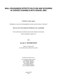
95% O2 and 5% CO2 air. Then, a temperature control system was designed using a flexible<br />
heating pad controlled by a thermocouple via a relay. The corresponding electrical circuit is<br />
represented in Figure 15. The heating pad is attached to the stretcher in order to warm up the<br />
silicone membrane mounted on it, as well as the cultured cardiomyocytes. The thermocouple<br />
senses the temperature of the silicone membrane and modifies the heating pad, in order to<br />
maintain the membrane temperature around 37ºC. If the SSR output generates current because the<br />
thermocouple senses a low membrane temperature, an electric field is created between the coil<br />
and the mechanical switch of the relay, making the switch attracted to the coil. Once the electrical<br />
circuit is closed, the heating pads can heat up. A relay was required as the 8V SSR output was not<br />
enough to directly control the heating pad which at least requires a 12V power supply.<br />
SSR activated<br />
voltage : open<br />
circuit 8V, short<br />
circuit 40 mA<br />
Relay<br />
J1, J2 : alarms<br />
controlling the<br />
SSR output<br />
Membrane<br />
TEMPERATURE CONTROLLER<br />
28<br />
Coil resistance :<br />
500 Ω<br />
Power<br />
supply :<br />
max 28 V<br />
SSR output<br />
Relay<br />
(mechanical switch)<br />
+ -<br />
RELAY<br />
Heating pads<br />
on stretcher<br />
Figure 15. Electrical circuit for the temperature control system [adapted from 60].