Experiences with Novel Secondary Conductivity Sensors within the ...
Experiences with Novel Secondary Conductivity Sensors within the ...
Experiences with Novel Secondary Conductivity Sensors within the ...

Create successful ePaper yourself
Turn your PDF publications into a flip-book with our unique Google optimized e-Paper software.
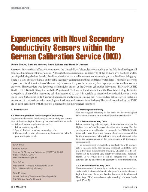
TECHNICAL PAPERS<br />
<strong>Experiences</strong> <strong>with</strong> <strong>Novel</strong> <strong>Secondary</strong><br />
<strong>Conductivity</strong> <strong>Sensors</strong> <strong>with</strong>in <strong>the</strong><br />
German Calibration Service (DKD)<br />
Ulrich Breuel, Barbara Werner, Petra Spitzer and Hans D. Jensen<br />
Abstract: International efforts concentrate on <strong>the</strong> traceability of electrolytic conductivity at <strong>the</strong> field level having small<br />
associated measurement uncertainties. Although <strong>the</strong> measurement of conductivity at <strong>the</strong> primary level has been widely<br />
developed during <strong>the</strong> last decade, <strong>the</strong> dissemination of <strong>the</strong> small measurement uncertainty to <strong>the</strong> field level is lagging.<br />
There is a lack of easy to handle and reliable secondary calibration methods and transfer standards.This paper describes<br />
a procedure for determination of <strong>the</strong> electrolytic conductivity on <strong>the</strong> secondary level appropriate for calibration laboratories.<br />
The procedure was developed <strong>with</strong>in a joint project of <strong>the</strong> German calibration laboratory (ZMK ANALYTIK<br />
GmbH, DKD-K-06901) toge<strong>the</strong>r <strong>with</strong> <strong>the</strong> Physikalisch-Technische Bundesanstalt and <strong>the</strong> Danish Metrology Institute.<br />
Altoge<strong>the</strong>r a chain of five measuring cells has been used so that it is possible to measure <strong>the</strong> conductivity over a wide<br />
range from 2 µS/cm up to 100 mS/cm.<strong>Experiences</strong> and first results using <strong>the</strong> five secondary cells are given including<br />
evaluation of comparisons <strong>with</strong> metrological institutes and partners from industry.The results obtained by <strong>the</strong> ZMK<br />
are in good agreement <strong>with</strong> <strong>the</strong> results obtained by <strong>the</strong> metrological institutes.<br />
1. Introduction<br />
1.1 Measuring Devices for Electrolytic <strong>Conductivity</strong><br />
In general to determine <strong>the</strong> electrolytic conductivity at a certain<br />
level of <strong>the</strong> metrological hierarchy (national and international)<br />
<strong>the</strong> followed measuring devices are used:<br />
1. Primary measuring cells.<br />
2. Special designed standard measuring cells.<br />
3. Commercial conductivity measuring instruments (<strong>with</strong> 2pole<br />
and 4-pole cells).<br />
Ulrich Breuel<br />
Barbara Werner<br />
Zentrum für Messen und Kalibrieren -ANALYTIK- GmbH<br />
D-06766 Wolfen, Germay<br />
Email: info@zmk-wolfen.de<br />
Petra Spitzer<br />
Physikalisch-Technische Bundesanstalt (PTB)<br />
D-38116 Braunschweig, Germany<br />
Hans D. Jensen<br />
Danish Institute of Fundamental Metrology (DFM)<br />
DK-2800 Kgs. Lyngby, Denmark<br />
1.2 Metrological Hierarchy<br />
The metrological hierarchy is <strong>the</strong> basis for <strong>the</strong> metrological<br />
infrastructure that is valid nationally and internationally.<br />
1.2.1 Primary Measuring Cells<br />
Primary measuring cells are a part of national standards at <strong>the</strong><br />
highest level of a calibration hierarchy in a country. For <strong>the</strong><br />
development of a calibration procedure in <strong>the</strong> DKD-K-06901,<br />
<strong>the</strong>se cells were important because <strong>the</strong>re are commonalities<br />
in <strong>the</strong> measurement <strong>with</strong> primary cells and standard cells.<br />
(e.g., <strong>the</strong> determination of <strong>the</strong> conductance <strong>with</strong> impedance<br />
measurement).<br />
The measurement of electrolytic conductivity <strong>with</strong> primary<br />
cells is traceable to <strong>the</strong> International System of Units (SI). There<br />
is a differential measurement principle. Changes of cells constants<br />
can be measured very exactly by dimensional measurements.<br />
[1–4] Fringe effects can be canceled out. The cell<br />
constant can be determined by geometrical measurements only.<br />
1.2.2 <strong>Secondary</strong> Measuring Cells<br />
The measurement of electrolytic conductivity by means of secondary<br />
cells is also carried out in a large scale in national metrological<br />
institutes. From <strong>the</strong> Danish Institute of Fundamental<br />
Metrology (DFM) several standard measuring cells were developed.<br />
[5, 6, 7]<br />
62 | MEASURE www.ncsli.org
Vol. 3 No. 2 • June 2008<br />
Primary cells<br />
(of <strong>the</strong> national<br />
metrology institute)<br />
Reference standards<br />
(Standard cells)<br />
Commercial measuring<br />
instruments and devices<br />
for electrolytic conductivity<br />
Calibration objects<br />
Figure 1. Metrological hierarchy of electrolytic conductivity.<br />
The aim of <strong>the</strong> project work done in <strong>the</strong><br />
DKD-K-06901 was <strong>the</strong> development of a<br />
metrological concept to measure <strong>the</strong> electrolytic<br />
conductivity in a wide range from<br />
2 µS/cm to 100 mS/cm. At <strong>the</strong> beginning<br />
only one standard measuring cell was<br />
available in <strong>the</strong> laboratory. This cell was<br />
applicable only for a limited measuring<br />
range from 100 µS/cm to 12 mS/cm. In<br />
order to be able to measure in <strong>the</strong> whole<br />
range of interest commercial devices and<br />
sensors were used. By means of this procedure,<br />
it was not possible to realize <strong>the</strong><br />
low target uncertainty <strong>the</strong> customers are<br />
asking for. On <strong>the</strong> o<strong>the</strong>r hand, an obvious<br />
limitation of <strong>the</strong> commercial instruments<br />
was <strong>the</strong> non-linearity. The metrological<br />
hierarchy for electrolytic conductivity is<br />
shown in Fig. 1.<br />
The standard cells in <strong>the</strong> middle of <strong>the</strong><br />
pyramid are <strong>the</strong> result of <strong>the</strong> development<br />
project. In <strong>the</strong> level of <strong>the</strong> secondary<br />
standards commercial measuring<br />
instruments and devices <strong>with</strong> several<br />
Transfer standards:<br />
Certified reference solutions<br />
for electrolytic conductivity<br />
sensors are used (e.g., 2-pole and 4-pole<br />
cells from WTW or Radiometer). 1<br />
1.3 Measuring Principle<br />
The measurement principle described in<br />
<strong>the</strong> following is valid likewise for<br />
primary cells and <strong>the</strong> standard cells. The<br />
complex conductance, G, or its reciprocal<br />
<strong>the</strong> complex resistance, is evaluated<br />
from a measurement at different frequencies.<br />
For a dc measurement, ei<strong>the</strong>r<br />
of <strong>the</strong>se two quantities would be enough.<br />
But in general <strong>the</strong> measurement is<br />
carried out <strong>with</strong> alternating current by<br />
means of an LCR-meter. The detected<br />
complex resistance during a measurement<br />
<strong>with</strong> ac is <strong>the</strong> impedance, Z, consisting<br />
of a real part, resistance, R, in<br />
ohms, and an imaginary part, X, <strong>the</strong> so<br />
called reactance. The relationship<br />
between <strong>the</strong>se quantities is shown in<br />
equation (1):<br />
Z = R + j X .<br />
(1)<br />
TECHNICAL PAPERS<br />
In equation (1), j is <strong>the</strong> imaginary unit.<br />
Similarly, <strong>the</strong> conductance can be<br />
described as <strong>the</strong> complex conductance,<br />
Y, consisting of a real, G, and an imaginary<br />
part, B:<br />
Y = G + j B .<br />
(2)<br />
The quantity B is referred <strong>the</strong> susceptance.<br />
In all measurements of electrolytic<br />
conductivity <strong>with</strong> primary and standard<br />
cells, <strong>the</strong> susceptance is part of <strong>the</strong> measured<br />
impedance. Therefore <strong>the</strong> conductance<br />
of <strong>the</strong> solution at infinite frequency<br />
has to be separated from <strong>the</strong> complex<br />
result. Because an infinite frequency is<br />
not realizable, <strong>the</strong> conductance at different<br />
frequencies is measured and plotted<br />
as a function of <strong>the</strong> reciprocal frequency<br />
(see Fig. 2).<br />
There is a good linearity between <strong>the</strong><br />
conductance and <strong>the</strong> reciprocal of <strong>the</strong> frequency<br />
over a given range. The intersection<br />
<strong>with</strong> <strong>the</strong> ordinate corresponds <strong>with</strong><br />
<strong>the</strong> conductance at an infinite frequency.<br />
This value is used for <strong>the</strong> determination<br />
of <strong>the</strong> cell constant of <strong>the</strong> standard measuring<br />
cells if <strong>the</strong> conductivity of <strong>the</strong> reference<br />
solution is known (e.g., certified<br />
reference solutions from DFM, National<br />
Institute of Standards and Technology<br />
(NIST) or Physikalisch-Technische Bundesanstalt<br />
(PTB)). After <strong>the</strong> cell constant<br />
is known, this value is used for <strong>the</strong> calculation<br />
of <strong>the</strong> electrolytic conductivity of<br />
solutions to be calibrated.<br />
For a precise evaluation, <strong>the</strong> choice of<br />
a suitable frequency range is very important.<br />
[8] A good linearity is not given<br />
using <strong>the</strong> whole frequency range. There<br />
are limits in <strong>the</strong> linearity at determined<br />
frequencies, but <strong>the</strong> limits depend on <strong>the</strong><br />
electrolytic conductivity of <strong>the</strong> solution.<br />
In general it is possible to say that it is<br />
better to use low frequencies for solutions<br />
<strong>with</strong> low electrolytic conductivity<br />
and high frequencies for solutions <strong>with</strong><br />
high electrolytic conductivity.<br />
During <strong>the</strong> work in <strong>the</strong> development<br />
project, different cell constants were<br />
realized for <strong>the</strong> whole measuring range<br />
from 2 µS/cm to > 100 mS/cm. The sig-<br />
1 Certain commercial equipment, instruments, or materials are identified in this paper in order to adequately describe <strong>the</strong> experimental procedure. Such<br />
identification does not imply recommendation or endorsement by <strong>the</strong> author or NCSL International, nor does it imply that <strong>the</strong> materials or equipment<br />
identified are <strong>the</strong> only or best available for <strong>the</strong> purpose.<br />
MEASURE | 63
TECHNICAL PAPERS<br />
G, µS<br />
838.00<br />
836.00<br />
834.00<br />
832.00<br />
830.00<br />
828.00<br />
826.00<br />
nificant frequencies were determined.<br />
1.4 Temperature Measurement<br />
Constant temperature of <strong>the</strong> measuring<br />
cells is an important precondition for <strong>the</strong><br />
determination of reproducible measurement<br />
results <strong>with</strong> low uncertainties.<br />
The homogeneity of <strong>the</strong> <strong>the</strong>rmostatic<br />
bath must be assured. Usually <strong>the</strong>rmometers<br />
<strong>with</strong> platinum elements of<br />
100 Ω (Pt100) or 25 Ω (Pt25)resistance<br />
1/f, Hz –1<br />
y = 970.1x + 837.7<br />
R 2 = 0.9995<br />
0.0000 0.0020 0.0040 0.0060 0.0080 0.0100 0.0120<br />
Figure 2. Conductance as a function of <strong>the</strong> reciprocal value of frequency.<br />
G, µS<br />
28.67<br />
28.66<br />
28.65<br />
28.64<br />
28.63<br />
28.62<br />
28.61<br />
28.60<br />
28.59<br />
28.58<br />
28.57<br />
0.0000 0.0100 0.0200 0.0300 0.0400 0.0500 0.0600<br />
Figure 3. Determination of <strong>the</strong> cell constant.<br />
1/f, Hz –1<br />
y = 1.7862x + 28.673<br />
R 2 = 0.9976<br />
are used as temperature sensors. The<br />
indication of <strong>the</strong> results is carried out <strong>with</strong><br />
resistance bridges (e.g., IsoTech Model<br />
TTI-2). It is important that <strong>the</strong> measurement<br />
uncertainty of <strong>the</strong> bath temperature<br />
is not higher than U = ± 5 mK (k = 2).<br />
2. Description of <strong>the</strong> Calibration<br />
Procedure<br />
As a result of <strong>the</strong> development project in<br />
<strong>the</strong> DKD-K-06901 a calibration proce-<br />
dure was developed that is based on <strong>the</strong><br />
use of standard measuring cells. Now it is<br />
possible to calibrate reference solutions<br />
for electrolytic conductivity over a range<br />
from 2 µS/cm to > 100 mS/cm.<br />
2.1 First Measurements <strong>with</strong> Standard<br />
Measuring Cells<br />
At <strong>the</strong> beginning, <strong>the</strong>re was one standard<br />
measuring cell available in <strong>the</strong> calibration<br />
laboratory, DKD-K-06901. Because<br />
of its cell constant (K = 1.67 cm -1 ), this<br />
measuring cell was suitable for <strong>the</strong> measurement<br />
in <strong>the</strong> range above 100 µS/cm.<br />
The question arose as to whe<strong>the</strong>r it is<br />
possible to also measure lower electrolytic<br />
conductivities <strong>with</strong> this cell.<br />
With decreasing electrolytic conductivity<br />
increasing deviations from a strong linearity<br />
were found for <strong>the</strong> conductance as<br />
a function of <strong>the</strong> reciprocal value of <strong>the</strong><br />
frequency. Because of <strong>the</strong>se strong deviations<br />
from a good linearity this standard<br />
measuring cell was not suitable for low<br />
conductivities in <strong>the</strong> pure water range.<br />
The development of a second cell <strong>with</strong><br />
a lower cell constant was necessary.<br />
The cell constant of this second cell<br />
(K = 0.1745 cm -1 ) was determined <strong>with</strong><br />
a certified reference solution (see Fig. 3).<br />
During <strong>the</strong> development project, it was<br />
apparent that <strong>the</strong> two standard measuring<br />
cells are not enough to carry out a<br />
measurement over such a wide range of<br />
electrolytic conductivity from 2 µS/cm to<br />
> 100 mS/cm. Altoge<strong>the</strong>r five standard<br />
measuring cells <strong>with</strong> different cell constants<br />
were used for <strong>the</strong> measurement of<br />
electrolytic conductivity.<br />
2.2 Standard Measuring Cells<br />
The standard measuring cells are special<br />
products (Sensortechnik Meinsberg<br />
GmbH) manufactured on <strong>the</strong> basis of a<br />
metrological conception. For a clear differentiation,<br />
each cell got a letter from A<br />
to E and a measuring range.<br />
All five standard measuring cells<br />
consist of a glass tube <strong>with</strong> two circular<br />
measuring electrodes (platinum, diameter<br />
20 mm). The distance between <strong>the</strong><br />
measuring electrodes is different from<br />
cell to cell. The measuring cells are fixed<br />
in a retaining device. A cover plate is<br />
made of metal and has grips to set <strong>the</strong><br />
cell into <strong>the</strong> <strong>the</strong>rmostatic bath. Connec-<br />
64 | MEASURE www.ncsli.org
Figure 4. Standard measuring cell D (example) for <strong>the</strong> determination<br />
of electrolytic conductivity.<br />
2 connections<br />
(for LCR-meter)<br />
tion to <strong>the</strong> LCR meter is realized <strong>with</strong> four connector sockets.<br />
Ano<strong>the</strong>r connector socket is used for an earth ground cable (see<br />
Figs. 4 and 5).<br />
The realization of different cell constants was reached by<br />
changing <strong>the</strong> distances and a treatment of <strong>the</strong> surface (platinising)<br />
of <strong>the</strong> measuring electrodes. With it measurements in different<br />
ranges of electrolytic conductivity are possible.<br />
Vol. 3 No. 2 • June 2008<br />
Openings for filling and emptying<br />
Measuring<br />
electrodes<br />
(Pt plate)<br />
Pt plate<br />
Solder connection<br />
(gold)<br />
2 connections<br />
(for LCR-meter)<br />
Figure 5. Schematic image of a standard measuring cell in <strong>the</strong><br />
DKD-K-06901.<br />
TECHNICAL PAPERS<br />
The ranges where a measurement of electrolytic conductivity<br />
is possible for each cell are overlapping. For a clear assignment,<br />
<strong>the</strong> used ranges are smaller. Figure 6 gives an overview over <strong>the</strong><br />
standard measuring cells.<br />
The measuring device consists of:<br />
1. Five standard measuring cells.<br />
2. LCR-meter (Agilent Model 4284A).<br />
3. Precision <strong>the</strong>rmostatic bath (oil bath, Lauda Proline Model<br />
PV 36).<br />
4. Temperature measuring device (temperature sensor Pt25<br />
and temperature indication instrument IsoTech TTI-2).<br />
2.3 Impedance Measurements <strong>with</strong> <strong>the</strong> LCR-meter<br />
Impedance measurements in <strong>the</strong> calibration laboratory DKD-K-<br />
06901 are carried out <strong>with</strong> <strong>the</strong> LCR-meter connected to <strong>the</strong><br />
standard measuring cells in 4-wire circuit. The cables used have<br />
a better electromagnetic shielding in comparison <strong>with</strong> <strong>the</strong> original<br />
cables from <strong>the</strong> manufacturer. With <strong>the</strong> LCR-meter, frequencies<br />
in <strong>the</strong> range from 20 Hz to 1 MHz are realizable, but,<br />
for our measurements, only a part of this range, from 20 Hz to<br />
5 kHz, was used.<br />
2.4 Stabilized Standard Measuring Cells and Temperature<br />
Measurement<br />
During <strong>the</strong> measurement <strong>the</strong> standard measuring cells are in <strong>the</strong><br />
precision <strong>the</strong>rmostatic bath. It is important that <strong>the</strong> time of tempering<br />
before <strong>the</strong> start of measurement is long enough. The temperature<br />
sensor (SPRT Pt25) used for <strong>the</strong> temperature<br />
measurement was calibrated at temperature fixed points. It is<br />
used toge<strong>the</strong>r <strong>with</strong> a temperature indication instrument TTI-2.<br />
For <strong>the</strong> realization of low measuring uncertainties it was necessary<br />
use a <strong>the</strong>rmostatic bath <strong>with</strong> a low temperature inhomogeneity<br />
for <strong>the</strong> tempering.<br />
The spatial inhomogeneity of <strong>the</strong> bath was determined <strong>with</strong><br />
platinum resistance <strong>the</strong>rmometers. One of <strong>the</strong>se <strong>the</strong>rmometers<br />
is <strong>the</strong> sensor Pt25 also used for <strong>the</strong> temperature control during<br />
<strong>the</strong> measurement. The sensor was fixed on a reference position<br />
in <strong>the</strong> centre between two measuring electrodes. Ano<strong>the</strong>r resistance<br />
<strong>the</strong>rmometer was positioned on two o<strong>the</strong>r measuring posi-<br />
4 mm 6 mm 20 mm 60 mm 60 mm<br />
Cell A Cell B Cell E<br />
Operating range<br />
Real measuring ranges are overlapping<br />
Figure 6. Operating ranges of <strong>the</strong> standard measuring cells in <strong>the</strong> DKD-K-06901.<br />
Plantinization<br />
Cell C Cell D<br />
2 µS/cm 15 µS/cm 100 µS/cm 1 mS/cm 20 mS/cm 100 mS/cm<br />
MEASURE | 65
TECHNICAL PAPERS<br />
H<br />
Reference position (Pt 25)<br />
during <strong>the</strong> determination of<br />
spatial inhomogenity<br />
tions one after ano<strong>the</strong>r. A spatial inhomogeneity<br />
of 2 mK was determined. Fur<strong>the</strong>rmore<br />
a time stability of <strong>the</strong><br />
<strong>the</strong>rmostatic bath of 3 mK was found.<br />
An additional temperature control is<br />
given by two calibrated liquid-in-glass<br />
<strong>the</strong>rmometers <strong>with</strong> a resolution of<br />
0.01 K. The <strong>the</strong>rmometers are positioned<br />
in direct near of <strong>the</strong> standard measuring<br />
cells (see Fig. 7).<br />
2.5 Metrological Traceability/<br />
Validation of <strong>the</strong> Calibration<br />
Procedure<br />
The standard measuring cells are traceable<br />
to <strong>the</strong> primary measuring cells of <strong>the</strong><br />
National Institute of Standards and Technology<br />
(NIST), <strong>the</strong> Physikalisch-Technische<br />
Bundesanstalt (PTB) or <strong>the</strong> Danish<br />
Institute of Fundamental Metrology<br />
(DFM) by certified reference solutions as<br />
transfer standards. In <strong>the</strong> frame of validation,<br />
extensive national and international<br />
comparisons were carried out. The<br />
recognition in national and international<br />
comparisons is <strong>the</strong> highest level of validation<br />
of <strong>the</strong> developed metrological procedure<br />
and is an important condition for<br />
an international offering of reference<br />
solutions of electrolytic conductivity as<br />
high-quality products.<br />
3. Conclusions<br />
Finally it is possible to say that <strong>the</strong> conception/creation<br />
of different standard<br />
measuring cells <strong>with</strong> accommodation to<br />
W<br />
1 2 3 1 2 3<br />
D<br />
Figure 7. Positions of <strong>the</strong> temperature sensors for <strong>the</strong> determination of spatial inhomogeneity (H, W, D are dimensions height, width and<br />
depth of <strong>the</strong> used volume).<br />
H<br />
defined measuring ranges is a new<br />
variant of <strong>the</strong> metrological trace-ability<br />
of electrolytic conductivity. The aim of<br />
this work is to supply reference solutions<br />
to users in <strong>the</strong> range from 2 µS/cm to ><br />
100 mS/cm, <strong>the</strong>reby providing users<br />
metrological traceability to <strong>the</strong> national<br />
level.” The standard measuring cells represent<br />
<strong>the</strong> level of reference standard in<br />
<strong>the</strong> metrological hierarchy of <strong>the</strong> procedure.<br />
With it <strong>the</strong> calibration of reference<br />
solutions of electrolytic conductivity is<br />
possible <strong>with</strong>out a break in <strong>the</strong> given<br />
measuring range. With this development<br />
for <strong>the</strong> industry/laboratories, <strong>the</strong>re is a<br />
new possibility to purchase reference<br />
solutions for <strong>the</strong> monitoring of <strong>the</strong><br />
processes and to save <strong>the</strong> accuracy of <strong>the</strong><br />
measuring results.<br />
4. Acknowledgments<br />
We thank <strong>the</strong> Landesförderinstitut<br />
Sachsen-Anhalt (Germany) for <strong>the</strong> financial<br />
support of <strong>the</strong> development project.<br />
The authors would like to acknowledge<br />
Dr. Reinhard Lange and Mr. Frank Seifert<br />
from Sensortechnik Meinsberg GmbH<br />
for <strong>the</strong>ir suggestions for <strong>the</strong> development<br />
of <strong>the</strong> standard measuring cells.<br />
5. References<br />
[1] P. Spitzer and U. Sudmeier, “Electrolytic<br />
conductivity – a new subject field at<br />
PTB,” PTB-report PTB-ThEx-15, PTB,<br />
Braunschweig, pp. 37–47, 2000.<br />
[2] K.W. Pratt, W.F. Koch, Y.C. Wu, and<br />
Position of <strong>the</strong> electrodes<br />
(cell C and D)<br />
during a measurement<br />
P.A. Berezansky, “Molality-based<br />
[3]<br />
primary standards of electrolytic conductivity,”<br />
Pure App. Chem., vol. 73, no.<br />
11, pp. 1783–1793, 2001.<br />
R.H. Shreiner and K.W. Pratt, “Standard<br />
reference materials: Primary standards<br />
and standard reference materials for<br />
electrolytic conductivity,” NIST Special<br />
Publication 260–142, 2004.<br />
[4] Y.C. Wu, W.F. Koch, and K.W. Pratt,<br />
“Proposed new electrolytic conductivity<br />
primary standards for KCl solutions,” J.<br />
Res. Natl. Stand. Technol., vol 96, pp.<br />
191–201, 1991.<br />
[5] H.D. Jensen and J. Sørensen, “Electrolytic<br />
conductivity at DFM – results<br />
and experiences,” PTB-Bericht PTB-<br />
ThEx-15, Braunschweig, pp. 3–8, 2000.<br />
[6] H.D. Jensen and C. Verdier, “Towards an<br />
improved primary standard for electrolytic<br />
conductivity,” presentation of <strong>the</strong><br />
Danish Institute of Fundamental Metrology<br />
at <strong>the</strong> NCSLI Workshop and Symposium,<br />
2001.<br />
[7] H.D. Jensen and N.-E. Dam, “DFM<br />
measurement capability: Electrolytic<br />
conductivity,” DFM-report DFM-04-<br />
[8]<br />
R81, Lyngby, pp. 1–7, January 2005.<br />
K. Rommel, “Leitfähigkeitsmessungen in<br />
Elektrolyten – Die Wahl der richtigen Frequenz,”<br />
off print from <strong>the</strong> Fachzeitschrift<br />
für Labortechnik, vol. 12, 1981.<br />
[9] “Guide to <strong>the</strong> Expression of Uncertainty<br />
in Measurement (GUM),” ISO/IEC<br />
Guide 98, International Organization for<br />
Standardization, Geneva, 1995.<br />
66 | MEASURE www.ncsli.org<br />
W<br />
D