Experiences with Novel Secondary Conductivity Sensors within the ...
Experiences with Novel Secondary Conductivity Sensors within the ...
Experiences with Novel Secondary Conductivity Sensors within the ...

You also want an ePaper? Increase the reach of your titles
YUMPU automatically turns print PDFs into web optimized ePapers that Google loves.
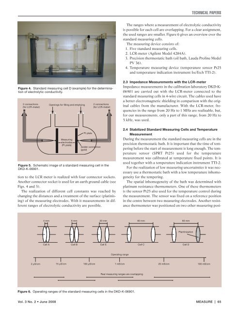
Figure 4. Standard measuring cell D (example) for <strong>the</strong> determination<br />
of electrolytic conductivity.<br />
2 connections<br />
(for LCR-meter)<br />
tion to <strong>the</strong> LCR meter is realized <strong>with</strong> four connector sockets.<br />
Ano<strong>the</strong>r connector socket is used for an earth ground cable (see<br />
Figs. 4 and 5).<br />
The realization of different cell constants was reached by<br />
changing <strong>the</strong> distances and a treatment of <strong>the</strong> surface (platinising)<br />
of <strong>the</strong> measuring electrodes. With it measurements in different<br />
ranges of electrolytic conductivity are possible.<br />
Vol. 3 No. 2 • June 2008<br />
Openings for filling and emptying<br />
Measuring<br />
electrodes<br />
(Pt plate)<br />
Pt plate<br />
Solder connection<br />
(gold)<br />
2 connections<br />
(for LCR-meter)<br />
Figure 5. Schematic image of a standard measuring cell in <strong>the</strong><br />
DKD-K-06901.<br />
TECHNICAL PAPERS<br />
The ranges where a measurement of electrolytic conductivity<br />
is possible for each cell are overlapping. For a clear assignment,<br />
<strong>the</strong> used ranges are smaller. Figure 6 gives an overview over <strong>the</strong><br />
standard measuring cells.<br />
The measuring device consists of:<br />
1. Five standard measuring cells.<br />
2. LCR-meter (Agilent Model 4284A).<br />
3. Precision <strong>the</strong>rmostatic bath (oil bath, Lauda Proline Model<br />
PV 36).<br />
4. Temperature measuring device (temperature sensor Pt25<br />
and temperature indication instrument IsoTech TTI-2).<br />
2.3 Impedance Measurements <strong>with</strong> <strong>the</strong> LCR-meter<br />
Impedance measurements in <strong>the</strong> calibration laboratory DKD-K-<br />
06901 are carried out <strong>with</strong> <strong>the</strong> LCR-meter connected to <strong>the</strong><br />
standard measuring cells in 4-wire circuit. The cables used have<br />
a better electromagnetic shielding in comparison <strong>with</strong> <strong>the</strong> original<br />
cables from <strong>the</strong> manufacturer. With <strong>the</strong> LCR-meter, frequencies<br />
in <strong>the</strong> range from 20 Hz to 1 MHz are realizable, but,<br />
for our measurements, only a part of this range, from 20 Hz to<br />
5 kHz, was used.<br />
2.4 Stabilized Standard Measuring Cells and Temperature<br />
Measurement<br />
During <strong>the</strong> measurement <strong>the</strong> standard measuring cells are in <strong>the</strong><br />
precision <strong>the</strong>rmostatic bath. It is important that <strong>the</strong> time of tempering<br />
before <strong>the</strong> start of measurement is long enough. The temperature<br />
sensor (SPRT Pt25) used for <strong>the</strong> temperature<br />
measurement was calibrated at temperature fixed points. It is<br />
used toge<strong>the</strong>r <strong>with</strong> a temperature indication instrument TTI-2.<br />
For <strong>the</strong> realization of low measuring uncertainties it was necessary<br />
use a <strong>the</strong>rmostatic bath <strong>with</strong> a low temperature inhomogeneity<br />
for <strong>the</strong> tempering.<br />
The spatial inhomogeneity of <strong>the</strong> bath was determined <strong>with</strong><br />
platinum resistance <strong>the</strong>rmometers. One of <strong>the</strong>se <strong>the</strong>rmometers<br />
is <strong>the</strong> sensor Pt25 also used for <strong>the</strong> temperature control during<br />
<strong>the</strong> measurement. The sensor was fixed on a reference position<br />
in <strong>the</strong> centre between two measuring electrodes. Ano<strong>the</strong>r resistance<br />
<strong>the</strong>rmometer was positioned on two o<strong>the</strong>r measuring posi-<br />
4 mm 6 mm 20 mm 60 mm 60 mm<br />
Cell A Cell B Cell E<br />
Operating range<br />
Real measuring ranges are overlapping<br />
Figure 6. Operating ranges of <strong>the</strong> standard measuring cells in <strong>the</strong> DKD-K-06901.<br />
Plantinization<br />
Cell C Cell D<br />
2 µS/cm 15 µS/cm 100 µS/cm 1 mS/cm 20 mS/cm 100 mS/cm<br />
MEASURE | 65