Experiences with Novel Secondary Conductivity Sensors within the ...
Experiences with Novel Secondary Conductivity Sensors within the ...
Experiences with Novel Secondary Conductivity Sensors within the ...

You also want an ePaper? Increase the reach of your titles
YUMPU automatically turns print PDFs into web optimized ePapers that Google loves.
Vol. 3 No. 2 • June 2008<br />
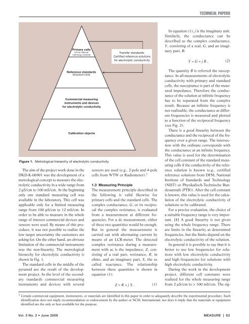
Primary cells<br />
(of <strong>the</strong> national<br />
metrology institute)<br />
Reference standards<br />
(Standard cells)<br />
Commercial measuring<br />
instruments and devices<br />
for electrolytic conductivity<br />
Calibration objects<br />
Figure 1. Metrological hierarchy of electrolytic conductivity.<br />
The aim of <strong>the</strong> project work done in <strong>the</strong><br />
DKD-K-06901 was <strong>the</strong> development of a<br />
metrological concept to measure <strong>the</strong> electrolytic<br />
conductivity in a wide range from<br />
2 µS/cm to 100 mS/cm. At <strong>the</strong> beginning<br />
only one standard measuring cell was<br />
available in <strong>the</strong> laboratory. This cell was<br />
applicable only for a limited measuring<br />
range from 100 µS/cm to 12 mS/cm. In<br />
order to be able to measure in <strong>the</strong> whole<br />
range of interest commercial devices and<br />
sensors were used. By means of this procedure,<br />
it was not possible to realize <strong>the</strong><br />
low target uncertainty <strong>the</strong> customers are<br />
asking for. On <strong>the</strong> o<strong>the</strong>r hand, an obvious<br />
limitation of <strong>the</strong> commercial instruments<br />
was <strong>the</strong> non-linearity. The metrological<br />
hierarchy for electrolytic conductivity is<br />
shown in Fig. 1.<br />
The standard cells in <strong>the</strong> middle of <strong>the</strong><br />
pyramid are <strong>the</strong> result of <strong>the</strong> development<br />
project. In <strong>the</strong> level of <strong>the</strong> secondary<br />
standards commercial measuring<br />
instruments and devices <strong>with</strong> several<br />
Transfer standards:<br />
Certified reference solutions<br />
for electrolytic conductivity<br />
sensors are used (e.g., 2-pole and 4-pole<br />
cells from WTW or Radiometer). 1<br />
1.3 Measuring Principle<br />
The measurement principle described in<br />
<strong>the</strong> following is valid likewise for<br />
primary cells and <strong>the</strong> standard cells. The<br />
complex conductance, G, or its reciprocal<br />
<strong>the</strong> complex resistance, is evaluated<br />
from a measurement at different frequencies.<br />
For a dc measurement, ei<strong>the</strong>r<br />
of <strong>the</strong>se two quantities would be enough.<br />
But in general <strong>the</strong> measurement is<br />
carried out <strong>with</strong> alternating current by<br />
means of an LCR-meter. The detected<br />
complex resistance during a measurement<br />
<strong>with</strong> ac is <strong>the</strong> impedance, Z, consisting<br />
of a real part, resistance, R, in<br />
ohms, and an imaginary part, X, <strong>the</strong> so<br />
called reactance. The relationship<br />
between <strong>the</strong>se quantities is shown in<br />
equation (1):<br />
Z = R + j X .<br />
(1)<br />
TECHNICAL PAPERS<br />
In equation (1), j is <strong>the</strong> imaginary unit.<br />
Similarly, <strong>the</strong> conductance can be<br />
described as <strong>the</strong> complex conductance,<br />
Y, consisting of a real, G, and an imaginary<br />
part, B:<br />
Y = G + j B .<br />
(2)<br />
The quantity B is referred <strong>the</strong> susceptance.<br />
In all measurements of electrolytic<br />
conductivity <strong>with</strong> primary and standard<br />
cells, <strong>the</strong> susceptance is part of <strong>the</strong> measured<br />
impedance. Therefore <strong>the</strong> conductance<br />
of <strong>the</strong> solution at infinite frequency<br />
has to be separated from <strong>the</strong> complex<br />
result. Because an infinite frequency is<br />
not realizable, <strong>the</strong> conductance at different<br />
frequencies is measured and plotted<br />
as a function of <strong>the</strong> reciprocal frequency<br />
(see Fig. 2).<br />
There is a good linearity between <strong>the</strong><br />
conductance and <strong>the</strong> reciprocal of <strong>the</strong> frequency<br />
over a given range. The intersection<br />
<strong>with</strong> <strong>the</strong> ordinate corresponds <strong>with</strong><br />
<strong>the</strong> conductance at an infinite frequency.<br />
This value is used for <strong>the</strong> determination<br />
of <strong>the</strong> cell constant of <strong>the</strong> standard measuring<br />
cells if <strong>the</strong> conductivity of <strong>the</strong> reference<br />
solution is known (e.g., certified<br />
reference solutions from DFM, National<br />
Institute of Standards and Technology<br />
(NIST) or Physikalisch-Technische Bundesanstalt<br />
(PTB)). After <strong>the</strong> cell constant<br />
is known, this value is used for <strong>the</strong> calculation<br />
of <strong>the</strong> electrolytic conductivity of<br />
solutions to be calibrated.<br />
For a precise evaluation, <strong>the</strong> choice of<br />
a suitable frequency range is very important.<br />
[8] A good linearity is not given<br />
using <strong>the</strong> whole frequency range. There<br />
are limits in <strong>the</strong> linearity at determined<br />
frequencies, but <strong>the</strong> limits depend on <strong>the</strong><br />
electrolytic conductivity of <strong>the</strong> solution.<br />
In general it is possible to say that it is<br />
better to use low frequencies for solutions<br />
<strong>with</strong> low electrolytic conductivity<br />
and high frequencies for solutions <strong>with</strong><br />
high electrolytic conductivity.<br />
During <strong>the</strong> work in <strong>the</strong> development<br />
project, different cell constants were<br />
realized for <strong>the</strong> whole measuring range<br />
from 2 µS/cm to > 100 mS/cm. The sig-<br />
1 Certain commercial equipment, instruments, or materials are identified in this paper in order to adequately describe <strong>the</strong> experimental procedure. Such<br />
identification does not imply recommendation or endorsement by <strong>the</strong> author or NCSL International, nor does it imply that <strong>the</strong> materials or equipment<br />
identified are <strong>the</strong> only or best available for <strong>the</strong> purpose.<br />
MEASURE | 63