Service Experience - MAN Diesel & Turbo - 首页
Service Experience - MAN Diesel & Turbo - 首页
Service Experience - MAN Diesel & Turbo - 首页

Create successful ePaper yourself
Turn your PDF publications into a flip-book with our unique Google optimized e-Paper software.
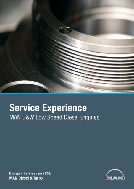
<strong>Service</strong> <strong>Experience</strong><br />
<strong>MAN</strong> B&W Low Speed <strong>Diesel</strong> Engines
Contents<br />
Introduction .................................................................................................3<br />
<strong>Service</strong> <strong>Experience</strong> Update ...........................................................................4<br />
ME System .............................................................................................4<br />
First <strong>Service</strong> Results for Mark 9 Large Bore and ME-B Engines .....................9<br />
7K80ME-C9 <strong>Service</strong> <strong>Experience</strong> .............................................................9<br />
General Update on ME and MC Engines ............................................... 14<br />
Welded Cylinder Frames ....................................................................... 18<br />
Condition Based Overhaul Strategy ............................................................ 20<br />
Condition Based Overhaul (CBO) of Pistons .......................................... 20<br />
CBO of Exhaust Valves ......................................................................... 22<br />
CBO of Bearings ................................................................................... 23<br />
Time Between Overhaul (TBO) for ......................................................... 25<br />
<strong>Turbo</strong>chargers ...................................................................................... 25<br />
Low Sulphur Fuel Operation ....................................................................... 26<br />
Catfines in Low Sulphur HFOs ............................................................... 26<br />
Cylinder Lubrication and Low Sulphur Fuels .......................................... 26<br />
Viscosity Issues .................................................................................... 27<br />
Burning Characteristics for Low Sulphur Fuels ....................................... 27<br />
Abatement Technologies ....................................................................... 27<br />
Gas Burning Low Speed Engines: ME-GI .............................................. 27<br />
Laying-Up of Vessels .................................................................................. 28<br />
Slow Steaming ........................................................................................... 29<br />
T/C Cut-out and Swing Gate Valve <strong>Experience</strong> ...................................... 31<br />
Conclusion ................................................................................................. 31<br />
References................................................................................................. 31
<strong>Service</strong> <strong>Experience</strong> of<br />
<strong>MAN</strong> B&W Low Speed <strong>Diesel</strong> Engines<br />
Introduction<br />
A very large number of MC & ME en-<br />
gines are entering service these years.<br />
The latest development of the most<br />
successful marine engine series ever<br />
is the ME-B series of which more than<br />
hundred engines are on order or delivered.<br />
The ME-B series are targeting<br />
the small bore end (35, 40, 46, 50 and<br />
60) of the <strong>MAN</strong> B&W low speed engine<br />
range.<br />
Electronically controlled low speed die-<br />
sels have been part of our engine pro-<br />
gramme for several years, actually since<br />
2001. Today, approx. 500 electronically<br />
controlled engines are in service, and<br />
focus on the electronically controlled<br />
engine versions is expected to increase<br />
with IMO Tier II emission rules coming<br />
into force for vessels with keel-laying<br />
after 1 January 2011. Also, because of<br />
this development the optimised ME-B<br />
engine range is very important and<br />
has already grabbed a lot of attention<br />
among shipowners.<br />
This paper deals with the latest service<br />
experience obtained so far from ME/<br />
ME-C engines in service. Early service<br />
experience for the 6S40ME-B will also<br />
be discussed.<br />
Advantages of upcoming ME software<br />
updates focusing on onboard trouble<br />
shooting will be described and related<br />
to service experience.<br />
Furthermore, an update on service experience<br />
of the MC/MC-C engine series<br />
will be given, focusing on the engine<br />
structure.<br />
Common for both the ME/ME-C and<br />
the MC/MC-C engine series is the welldocumented<br />
possibility to do Condition<br />
Based Overhaul (CBO) with an average<br />
Time Between Overhauls (TBOs) of<br />
32,000 hours and higher. For tankers,<br />
this opens up the possibility of doing<br />
only major overhauls at dockings with<br />
5-year intervals. Many shipowners have<br />
now had the positive experience of<br />
CBO. Also the development in relation<br />
to cylinder condition with focus on cylinder<br />
oil consumption will be touched<br />
upon.<br />
Due to the present economic crisis, fo-<br />
cus has lately generally been devoted<br />
to optimisation of low load operation. In<br />
early 2009, <strong>MAN</strong> <strong>Diesel</strong> & <strong>Turbo</strong> issued<br />
a <strong>Service</strong> Letter dealing with the possibility<br />
of operating continuously down<br />
to 10% load. <strong>Service</strong> tests with various<br />
scavenge air pressure increasing measures<br />
at low load have also been carried<br />
out. Here, tests with turbocharger cutout,<br />
Variable Turbine Area (VTA) turbochargers<br />
and exhaust gas bypass are<br />
the most important ones. The test results<br />
will also be discussed.<br />
<strong>Service</strong> <strong>Experience</strong> of <strong>MAN</strong> B&W Low Speed <strong>Diesel</strong> Engines<br />
3
<strong>Service</strong> <strong>Experience</strong> Update<br />
ME System<br />
Over the past years, we have described<br />
various areas with room for improvement<br />
on the ME system in a number<br />
of papers dealing with service experience.<br />
The most recent paper is <strong>Service</strong><br />
<strong>Experience</strong> 2008, <strong>MAN</strong> B&W Engines,<br />
Ref. [1].<br />
In this paper, we will comment on is-<br />
sues which are still undergoing investi-<br />
gation at the time of writing. Also, future<br />
planned upgrades will be mentioned.<br />
Especially the trouble-shooting tools<br />
implemented in a new ECS software<br />
version will be commented on.<br />
Cavitation damage in the exhaust valve<br />
actuation system<br />
Fig. 1 shows cavitation damage in the<br />
high pressure pipe between the exhaust<br />
actuator and the exhaust valve.<br />
Also cavitation damage in the actuator<br />
top cover and in the top of the exhaust<br />
valve can be seen. This kind of damage<br />
is seen on the large bore versions of the<br />
ME engine (80, 90 and 98-cm bore),<br />
Fig. 1: Cavitation in hydraulic exhaust actuation system<br />
4 <strong>Service</strong> <strong>Experience</strong> of <strong>MAN</strong> B&W Low Speed <strong>Diesel</strong> Engines<br />
however, not to the same extent on all<br />
units on the engine. Therefore, damage<br />
can be counteracted by relatively small<br />
changes.<br />
<strong>Service</strong> tests where the proportional<br />
feature of the FIVA valve is used are<br />
70<br />
60<br />
50<br />
40<br />
30<br />
20<br />
10<br />
Use of Proportional (FIVA) Control for Exhaust Valve Actuation<br />
0<br />
4000 4500 5000 5500 6000 6500 7000 7500 8000<br />
Fig. 2: Use of proportional (FIVA) control for exhaust valve actuation<br />
presently ongoing. So far, we have only<br />
used the proportional control of the FIVA<br />
valve for injection rate shaping, but now<br />
we also use it in order to open and close<br />
the exhaust valve gently. Fig. 2 shows<br />
the original lifting curve and the modified<br />
lifting curve of the exhaust valve. No<br />
Cyl. 6 Exhaust valve org.<br />
Cyl. 7 Exhaust valve test.
A B C On a few actuators for the original 200<br />
bar hydraulic system, we have seen<br />
breakage of the step 1 piston collar,<br />
Fig. 4. We are convinced that this problem<br />
relates to delayed “take-off” of the<br />
step 1 piston from the bottom position,<br />
Fig. 3 (A). This is caused by a “glue”<br />
effect, which exists from time to time.<br />
When the step 1 piston is delayed it will<br />
create very high pressures in the “damper”<br />
chamber and hereby increased load<br />
on the piston collar is generated. Various<br />
means to avoid the “glue” effect<br />
can be introduced by generating a force<br />
Fig. 3: Exhaust actuator<br />
by the oil pressure under the step 1 piston.<br />
An example of retrofit is illustrated<br />
in Fig. 5. Such design modifications will<br />
big changes can be seen. However, the how the step 1 piston is stopped in the eliminate the trouble with step 1 piston<br />
oil pressure fluctuations in the actuator “damper” as the step 2 piston contin- breakage.<br />
system are modified to some extent, ues its movement upward. In Fig. 3 (C),<br />
and we expect that this will reduce/ the step 2 piston has arrived at its top Cavitation in the pilot step of the FIVA valve<br />
eliminate the cavitation damage in the position caught by another “damper”. We have seen cavitation attacks on the<br />
exhaust actuation system.<br />
pilot spools of both the Curtis Wright<br />
Exhaust actuator piston breakage<br />
The exhaust actuator for the ME engines<br />
is a two-step actuator. The principle<br />
of function is shown in Fig. 3. Fig.3<br />
(A) shows both pistons (step 1 and step<br />
2) in bottom position. Fig. 3 (B) illustrates<br />
Fig. 4: Piston collar breakage<br />
Problem Countermeasure<br />
“Glue” effect between piston step No. 1 and<br />
distributor block, causing a launch delay for<br />
piston No. 1.<br />
Fig. 5: Example of retrofit<br />
Area of contact causing glue effect<br />
Grinding grooves in piston No. 1 for easy<br />
relief. Grooves: 8 x R 0.5 mm w. depth of<br />
approx. 0.3 mm.<br />
Relief grooves<br />
<strong>Service</strong> <strong>Experience</strong> of <strong>MAN</strong> B&W Low Speed <strong>Diesel</strong> Engines<br />
5
Fig. 6: Curtis Wright FIVA: cavitation on pilot spool<br />
Fig. 7: <strong>MAN</strong> B&W FIVA: cavitation on Parker valve pilot spool<br />
FIVA valve, see Fig. 6, and the Parker<br />
valve on the <strong>MAN</strong> B&W FIVA valve,<br />
see Fig. 7. Presently, this limits the<br />
overhaul intervals of the FIVA valves to<br />
some 8,000-10,000 hours. Our goal<br />
for overhaul intervals on FIVA valves is<br />
32,000 hours.<br />
The cavitation damage on the Parker<br />
spools is mainly related to the tank ports<br />
for the pilot step. We have therefore designed<br />
two (2) service tests, which are<br />
currently accumulating hours on two (2)<br />
12K98ME plants. Fig. 8 shows the test<br />
6 <strong>Service</strong> <strong>Experience</strong> of <strong>MAN</strong> B&W Low Speed <strong>Diesel</strong> Engines<br />
FIVA with the pilot tank port connected<br />
to the FIVA main spool pressurised tank<br />
port. Fig. 9 shows the other FIVA valve<br />
with the pilot tank port connected to a<br />
completely pressure-less drain.<br />
On the basis of these test results, we<br />
will conclude final countermeasures in<br />
order to extend overhaul intervals to<br />
an acceptable time span. Preliminary<br />
inspection results from the service test<br />
indicate that cavitation countermeasure<br />
test 1, the pressurised submerged<br />
drain, is the most successful solution.<br />
Original Modified<br />
Tank outlet from<br />
control valve is sent<br />
directly to drain<br />
Fig. 8: <strong>MAN</strong> B&W FIVA: Cavitation countermeasure test 1<br />
Original Modified<br />
Fig. 9: <strong>MAN</strong> B&W FIVA: Cavitation countermeasure test 2<br />
Tank outlet<br />
from control<br />
valve is sent<br />
via tank outlet<br />
for main valve<br />
Parker tank port<br />
connected to new<br />
atmospheric drain<br />
However, more service hours are needed<br />
to make the final conclusion.<br />
Untimed injection with the <strong>MAN</strong> B&W FIVA<br />
valve<br />
For the <strong>MAN</strong> B&W FIVA valve, we have<br />
experienced an untimed injection in<br />
one single case on one cylinder unit on<br />
a 6S60ME-C engine in August 2009.<br />
The over-pressure in the cylinder resulting<br />
from the untimed injection did not<br />
cause any damage to the mechanical<br />
parts because of the built-in safety margin<br />
in the various components, such
Broken Litz wire<br />
Fig. 10: Parker pilot valve<br />
as the piston rod, connecting rod and<br />
crankshaft. The failing FIVA valve was<br />
returned, and investigations showed<br />
that the problem was related to the pilot<br />
step, the Parker valve. Close investigations<br />
together with the sub-supplier revealed<br />
that a broken wire, a so-called<br />
Litz wire, had caused the malfunction of<br />
the Parker valve, see Fig. 10.<br />
Tests also revealed that the broken<br />
Litz wire resulted in an overshoot and<br />
that explained the untimed fuel injection<br />
experienced in the vessel with the<br />
6S60ME-C engine.<br />
Production of the Parker valves was<br />
changed based on this experience,<br />
and zener diodes were included in the<br />
electronic control design of the Parker<br />
valve. These diodes eliminate overshoot<br />
in case of a broken Litz wire.<br />
Investigations of Parker valves with dif-<br />
ferent numbers of operating hours have<br />
been concluded, and Parker valves with<br />
low serial numbers have been recalled<br />
from service.<br />
Parker valve with voice coil drive<br />
Multi Purpose Controller (MPC) quality<br />
In order to improve the quality of the<br />
MPCs, we have introduced so-called<br />
“burn-in” tests of all MPCs produced.<br />
The background is an investigation<br />
of more than 100 returned MPCs. Of<br />
these, approx. 25% did not show failure<br />
until they were subjected to the<br />
“burn-in” test. With the introduction of<br />
full scale burn-in tests, we expect that<br />
the MPC failure rate will be reduced sig-<br />
Fig. 11: New ECS software with trouble shooting screens: HCU event recorder<br />
Fig. 12: New ECS software with trouble shooting screens: Tacho adjustment<br />
<strong>Service</strong> <strong>Experience</strong> of <strong>MAN</strong> B&W Low Speed <strong>Diesel</strong> Engines<br />
7
nificantly, especially during the commis-<br />
sioning stage (shop test, quay trial and<br />
sea trial).<br />
New updated ECS software<br />
A new version of the Engine Control<br />
System (ECS) software will soon be<br />
introduced both to new engines and<br />
to engines in service. The main focus<br />
for this software is to provide better<br />
trouble-shooting tools onboard vessels<br />
equipped with ME engines.<br />
Various new screens on the MOP have<br />
been developed in order to assist the<br />
engine crew in more qualified trouble<br />
shooting. An example is the “HCU event<br />
recorder” and the related MOP screen,<br />
see Fig. 11. The ‘‘HCU event recorder’’<br />
records a number of predetermined<br />
signals related to the HCU (Hydraulic<br />
Cylinder Unit) continuously. If an alarm<br />
Fig. 13: Large cabinet with MPCs suited for engine<br />
8 <strong>Service</strong> <strong>Experience</strong> of <strong>MAN</strong> B&W Low Speed <strong>Diesel</strong> Engines<br />
related to the HCU is activated, a record<br />
of signals is stored and can later be<br />
seen on the MOP, some r/min before<br />
activation of the alarm and some r/min<br />
after. This will assist the engine crew in<br />
locating the reason for the alarm.<br />
Another example of improved support<br />
to the engine crew is the tacho adjustment<br />
screen, see Fig. 12. This MOP<br />
screen assists the engine crew in making<br />
re-adjustments to the tacho system.<br />
There are a number of other new<br />
screens relating to the HCU and the<br />
HPS (Hydraulic Power Supply). Altogether,<br />
the new software will enable<br />
much more qualified trouble shooting<br />
onboard.<br />
Fig. 14: Exhaust valve drain line with drain box<br />
Off-engine located MPCs<br />
As an alternative to the MPCs located<br />
on the engine, we have introduced a<br />
design where the MPCs are located in<br />
larger cabinets, see Fig. 13, which can<br />
be located away from the engine, e.g.<br />
in the engine control room, in a switchboard<br />
room or directly in the engine<br />
room. From now on, we will gain experience<br />
with respect to i.a. lifetime of the<br />
MPCs. Also, possible production benefits<br />
of the alternative execution can be<br />
measured in the future.<br />
Drain box for the exhaust valve drain lines<br />
On 80-cm and 98-cm bore engines, we<br />
have seen breakage of the drain lines<br />
from the exhaust valve. A design with<br />
a so-called drain box, see Fig. 14, has<br />
been tested successfully. This design<br />
will counteract the trouble with drain<br />
line breakage.
First <strong>Service</strong> Results for Mark 9 Large<br />
Bore and ME-B Engines<br />
7K80ME-C9 <strong>Service</strong> <strong>Experience</strong><br />
At the time of writing, the first four large<br />
bore 7K80ME-C9 engines are in service.<br />
Combustion chamber components have<br />
been updated with additional features for<br />
the high-rated large bore Mark 9 engine<br />
series. Some of these features are:<br />
Pitch-honed cylinder liners<br />
CPR top piston ring with a thick alucoat<br />
on top of cermet coating<br />
Mo-coated barrel-shaped piston skirt<br />
Piston cleaning ring of asymmetric<br />
design.<br />
Pitch honing means that the semi-honing<br />
has been updated to include honing<br />
of the liner surface grooves (wave cut).<br />
A thick alu-coat gives more safe running<br />
in properties of the piston ring package.<br />
Mo-coated barrel-shaped piston skirts<br />
have been tested with good results for<br />
a long time on a number of large bore<br />
engines. Cost down potential exists for<br />
this design.<br />
An asymmetric piston cleaning ring<br />
gives a better cleaning effect on the piston<br />
top land in the exhaust side.<br />
Scavenge port inspection has been car-<br />
ried out after 1,842 running hours. The<br />
results can be seen in Figs. 15 and 16<br />
for piston ring and piston skirt condition,<br />
respectively. Fig. 17 shows the<br />
pitch-honed liner from the scavenge<br />
ports. All inspection areas indicate that<br />
Fig. 15: Piston ring condition<br />
Fig. 16: Piston skirt view<br />
very successful running-in has taken<br />
place and that the cylinder condition for<br />
all units is excellent.<br />
A further inspection was carried out<br />
after 3,800 running hours. One cylinder<br />
unit was opened up for inspection and<br />
liner calibration. Fig. 18 shows the top<br />
of the liner. The max. wear rate is 0.037<br />
mm/1000 hrs. at the top dead centre<br />
of piston ring No. 2. This wear rate includes<br />
initial running-in wear and is very<br />
satisfactory.<br />
Fig. 19 shows a close-up of the cylinder<br />
liner surface. The open graphite structure<br />
is clearly seen. This surface structure<br />
indicates a successful temperature<br />
control on the liner surface and, hereby,<br />
a controlled acid corrosion level.<br />
A new main bearing design concept has<br />
been introduced on the 7K80ME-C9.<br />
The result of this new design concept<br />
is improved productivity during machining<br />
of the bedplate. Figs. 20 to 23 show<br />
the results of the ovehaul inspection of<br />
main bearing No. 5 after 3,800 hours.<br />
<strong>Service</strong> <strong>Experience</strong> of <strong>MAN</strong> B&W Low Speed <strong>Diesel</strong> Engines<br />
9
Fig. 17: Pitch-honed liner<br />
Fig. 18: Top of liner after 3,800 hrs.<br />
Fig. 19: Close-up of cylinder liner: open graphite structure visible<br />
10 <strong>Service</strong> <strong>Experience</strong> of <strong>MAN</strong> B&W Low Speed <strong>Diesel</strong> Engines<br />
Fig. 20: High-friction shim and guide pin<br />
Fig. 21: Main bearing cap and bedplate contact area
Fig. 22: Upper main bearing shell backside<br />
Fig. 23: Lower and upper shell, white-metal side<br />
The inspection results indicate excellent<br />
condition with respect to contact surfaces,<br />
with signs of relative movements<br />
as well as very good main bearing shell<br />
load imprints.<br />
ME-B9 service experience<br />
At the time of writing, two 6S40ME-<br />
B9 and two 8S35ME-B9 engines are<br />
in service. A scavenge port inspection<br />
was made after 2,574 hours of operation<br />
on the 6S40ME-B9 prototype. Fig.<br />
24 shows pictures from this inspection.<br />
The pistons are equipped with an alucoat<br />
ring pack. As shown, running-in has<br />
finished, and the piston ring base material<br />
is working directly against the cylinder<br />
liners. Light piston topland deposits are<br />
seen.<br />
We are using the S40ME-B9 engine<br />
prototype for cylinder oil feed rate tests.<br />
The aim is to come down to the feed<br />
rate used as standard for >60 bore engines<br />
(0.20 g/kWhXS%, minimum 0.6<br />
g/kWh). These tests look very promis-<br />
ing, and a new service letter for small<br />
bore engines on reduced cylinder oil<br />
feed rate is expected soon.<br />
A piston overhaul was carried out after<br />
4,000 running hours to inspect the condition<br />
of the new piston design, see Fig.<br />
25, applied on the S40ME-B9 engines.<br />
Fig. 26 indicates a very good condition<br />
of the piston topland (light deposits),<br />
piston rings (surface without any signs<br />
of seizures) and piston skirt (perfect<br />
condition of the bronze band).<br />
<strong>Service</strong> <strong>Experience</strong> of <strong>MAN</strong> B&W Low Speed <strong>Diesel</strong> Engines<br />
11
Unit No. 1:<br />
Running hours: 2,574<br />
Condition: Good. No signs of abnormal wear or micro-seizures.<br />
No alu-coating left<br />
Present cylinder oil dosage: 0.75 g/kWh<br />
Recommended cylinder oil<br />
dosage:<br />
CL groove: Not accessible<br />
Topland: Light deposits<br />
Fig. 24: Scavenge port inspection<br />
Fig. 25: ME-B9 piston design<br />
Keep lubricating according to the cylinder oil test by following<br />
service letter SL09-507<br />
12 <strong>Service</strong> <strong>Experience</strong> of <strong>MAN</strong> B&W Low Speed <strong>Diesel</strong> Engines<br />
Bore cooled<br />
piston crown<br />
Ring pack, same as<br />
for existing engines<br />
(alu-coat)<br />
Copper band<br />
Fig. 26: ME-B9 piston after 4,000 hrs
Two-pad type pressure distribution Wide-pad type pressure distribution<br />
Improved oil film thickness<br />
Fig. 27: ME-B9 crosshead bearing design<br />
Fig. 28: ME-B9 crosshead bearing after 4,000 hrs.<br />
A new design of the slim type connect-<br />
ing rod and the wide-pad crosshead<br />
lower bearing shell, see Fig. 27, has<br />
been introduced on the ME-B9 engines.<br />
Fig. 28 shows the lower crosshead<br />
bearing shell of unit No. 6 at an<br />
inspection after 4,000 running hours.<br />
The bearing imprint is, as expected, in<br />
good condition.<br />
<strong>Service</strong> <strong>Experience</strong> of <strong>MAN</strong> B&W Low Speed <strong>Diesel</strong> Engines<br />
13
General Update on ME and MC<br />
Engines<br />
Apart from ME system specific issues,<br />
we also have certain areas of attention,<br />
which are common for the electronically<br />
controlled ME engines and the camshaft<br />
controlled MC engines. In this<br />
paper, we also focus on the cylinder<br />
condition of large bore engines, lifting<br />
bracket cracks on large bore engine<br />
bedplates and cracks in the first generation<br />
of welded cylinder frames.<br />
Cylinder condition, large bore engines<br />
In general, we experience very satisfactory<br />
wear figures on both cylinder liners<br />
and piston rings on large bore engines.<br />
This has enabled an extension of overhaul<br />
intervals, and strategy overhaul<br />
intervals, above 32,000 hours (5 years)<br />
can be obtained when applying condition<br />
based overhaul (CBO). This is described<br />
in our service letter SL07-483/<br />
HRR, Ref. [2], and further in the paper<br />
<strong>Service</strong> <strong>Experience</strong> 2008, <strong>MAN</strong> B&W<br />
Engines, Ref. [1]. We will deal with condition<br />
based overhaul strategy in details<br />
in the next section of this paper.<br />
However, from time to time, the generally<br />
good wear figures are disturbed<br />
by cylinder liner scuffing. The reasons<br />
for cylinder liner scuffing are many, and<br />
often caused by several factors. The<br />
major reasons for cylinder liner scuffing<br />
include:<br />
Bore polish due to surplus of alkali<br />
additive (excessive lubrication)<br />
Broken down oil film as a result of too<br />
rapid load changes<br />
Water ingress due to inefficient water<br />
separation<br />
14 <strong>Service</strong> <strong>Experience</strong> of <strong>MAN</strong> B&W Low Speed <strong>Diesel</strong> Engines<br />
Fig. 29: Increased focus on piston ring quality and liner surface quality<br />
Catfines in the fuel – wear out of the<br />
CL grooves/broken rings<br />
Running-in problems.<br />
Lately, we have had to focus on running-in<br />
problems, typically at running<br />
hours between 500 and 1,000. The<br />
reason for the running-in problems is<br />
the piston ring quality in combination<br />
with the cylinder liner surface quality.<br />
Fig. 29 shows a severe case of runningin<br />
problems due to embedded iron on<br />
Delaminated<br />
Cermet + Iron<br />
Fig. 30: Piston ring quality<br />
Alu-coat<br />
Running-in:<br />
Severe cases of embedded<br />
iron and subsequent<br />
scuffing<br />
the outside of the running-in alu-coat<br />
layer, peeling-off of the alu-coat/iron<br />
layer and subsequent scuffing. A detailed<br />
analysis of such problems has led<br />
to increased focus on:<br />
Piston ring quality<br />
Liner surface quality/finish.<br />
Fig. 30 shows cross sections of piston<br />
rings with iron and cermet (delaminated)<br />
layers positioned on top of the alu-coat<br />
Cermet coating<br />
A-A
layer during running-in, leading to un-<br />
stable cylinder condition caused by the<br />
quality of the cermet coating.<br />
Fig. 31 shows an example of off-spec.<br />
honing of the cylinder liner surface. The<br />
honed area must nominally be 50% of<br />
the liner surface. As can be seen on the<br />
photo, the honed area is much smaller<br />
resulting in much tougher running-in<br />
and an increased production of ‘lineriron’.<br />
The photo shows an unused<br />
spare cylinder liner on a vessel where<br />
cylinder liner scuffing has occurred.<br />
During the last part of 2009 and the<br />
first part of 2010, we carried out a piston<br />
ring exchange programme where<br />
around 1,000 cylinder units of K98 and<br />
K90 engines were exchanged before<br />
ship delivery in order to gain control in<br />
relation to piston ring quality. The cermet<br />
coating specification and the quality<br />
of the cermet coating were reformulated.<br />
During this process also cylinder<br />
Air cooler<br />
Air flow<br />
Air flow<br />
Fig. 32: Full scale test installation<br />
Engine design<br />
Water mist catcher<br />
Fig. 31: Cylinder liner quality: insufficient plateau honing<br />
Air flow<br />
liner machining was checked and Air flowre<br />
honing was carried out in case of offspec.<br />
condition.<br />
Turning<br />
chamber<br />
Another recent focus area has been<br />
the design and efficiency of water mist<br />
catchers. Fig. 32 shows the full scale<br />
Test arrangement<br />
<strong>Service</strong> <strong>Experience</strong> of <strong>MAN</strong> B&W Low Speed <strong>Diesel</strong> Engines<br />
15
test installation of a water mist catcher.<br />
We have made a full scale test on various<br />
water mist catcher designs, including<br />
some sub-supplied designs, which<br />
<strong>MAN</strong> <strong>Diesel</strong> & <strong>Turbo</strong> design Sub-supplier I Sub-supplier II<br />
Fig. 33: Tested designs<br />
Efficiency [%]<br />
100 100<br />
90 90<br />
80 80<br />
70 70<br />
60 60<br />
50 50<br />
40 40<br />
30 30<br />
20 20<br />
10 10<br />
94,8 94.8 94,7 94.7<br />
88,7 88.7<br />
69.7 69,7<br />
16 <strong>Service</strong> <strong>Experience</strong> of <strong>MAN</strong> B&W Low Speed <strong>Diesel</strong> Engines<br />
have been applied in big numbers in our<br />
large bore engines. Fig. 33 shows three<br />
of the tested designs and Fig. 34 shows<br />
an example of the results obtained. In<br />
WMC efficiency as function a function of of air air velocity velocity<br />
Constant boundary boundary conditions: conditions<br />
Mass flow of water = 0.0016 kg/s<br />
Massflow Air temperature of water = 25 ≈ 0.016 kg/s<br />
Air temperature ≈ 25 C<br />
Air absolute pressure ≈ 3.5 bara<br />
oC Air absolute pressure = 3.5 bara<br />
88.2<br />
88,2<br />
66.8<br />
66,8<br />
92.6 92,6<br />
84.1 84,1<br />
63.3<br />
63,3<br />
<strong>MAN</strong> <strong>Diesel</strong> & design <strong>Turbo</strong><br />
Sub-supplier Design II<br />
Sub-supplier II I<br />
0 0<br />
5.5 6 6.5 7 7.5 8<br />
5,5 6 6,5 7 7,5 Velocity [m/s] 8<br />
Velocity[m/s]<br />
Fig. 34: Full scale test results<br />
this case, the water mist catching efficiency<br />
is shown as a function of air<br />
velocity and very big deviations in efficiency<br />
can be seen.<br />
On the basis of these results and an up-<br />
date of the mechanical design, we have<br />
now fully re-specified the water mist<br />
catcher design, and we expect that this<br />
will limit water ingress related scuffing.<br />
Cracks in the bedplate lifting bracket of K98<br />
engines<br />
In 2008, cracks in the lifting bracket<br />
on K98 bedplates were discovered on<br />
engines produced 5-7 years earlier,<br />
see Fig. 35. Soon after the first cracks<br />
were discovered, a so-called ‘Circular<br />
Letter’ was issued to all owners/operators<br />
of K98 engines, see Fig. 36. In<br />
this letter we asked for help to inspect<br />
for lifting bracket cracks. Furthermore,<br />
we informed about preventive countermeasures,<br />
which were burr grinding<br />
of the weld seams on the aftmost and<br />
foremost brackets. Also, a repair procedure<br />
was developed when the cracks<br />
first occurred. A modified bracket profile<br />
has been designed for new engines,<br />
see Fig. 37.<br />
Due to the high number of K98 engines<br />
in service, these rectifications are still<br />
ongoing and, fortunately, we are able to<br />
perform this work without disturbing the<br />
operation of the vessels involved.
Fig. 35: Lifting bracket cracks<br />
All lifting brackets on both manoeuvring<br />
and exhaust side to be inspected<br />
Fig. 36: Circular letter: K98 lifting bracket cracks<br />
Fig. 37: Lifting bracket cracks: design update<br />
Possible crack at upper<br />
welding toe at lifting bracket<br />
Possible crack at upper<br />
welding toe at foot flange<br />
12 cylinder bedplate shown<br />
Careful inspection of fore and aft-most<br />
lifting brackets on both manoeuvring and<br />
exhaust side<br />
MD standard MD updated<br />
<strong>Service</strong> <strong>Experience</strong> of <strong>MAN</strong> B&W Low Speed <strong>Diesel</strong> Engines<br />
17
Fig. 38: Welded cylinder frame with integrated scavenge air receiver<br />
New bent type Old design<br />
Fig. 39: Welded cylinder frame: fatigue crack originating from stay bolt covers<br />
18 <strong>Service</strong> <strong>Experience</strong> of <strong>MAN</strong> B&W Low Speed <strong>Diesel</strong> Engines<br />
Welded Cylinder Frames<br />
As an alternative to cast iron cylinder<br />
frames, a welded version of the<br />
cylinder frame has been introduced.<br />
Fig. 38 shows a 7-cylinder welded cylinder<br />
frame with an integrated scavenge<br />
air receiver. The first generation of the<br />
welded cylinder frame showed, in some<br />
cases, cracks originating from the stay<br />
bolt covers, see Fig. 39. A new bent<br />
type stay bolt cover has been designed,<br />
and attachment to the main cylinder<br />
frame structure at a position with a lower<br />
stress level has been realised.<br />
Fig. 40 shows the newest version of the<br />
welded cylinder frame for a 80ME-C<br />
Mk 9 engine. On the exhaust side, the<br />
bent type stay bolt cover is applied, and<br />
on the pump side the stay bolt cover is<br />
omitted.
New type<br />
Old type<br />
Thin, bent stay bolt cover in exhaust side. New type/old type<br />
Fig. 40: Welded cylinder frame: old and new type stay bolt cover designs<br />
We are confident that the crack prob-<br />
lems related to the stay bolt cover<br />
plates have now been eliminated. For<br />
engines in service with first generation<br />
welded cylinder frames, repair work is<br />
in progress.<br />
Pump side stay bolt cover omitted. Stay bolt visible<br />
<strong>Service</strong> <strong>Experience</strong> of <strong>MAN</strong> B&W Low Speed <strong>Diesel</strong> Engines<br />
19
Condition Based Overhaul Strategy<br />
In the following, we will describe the<br />
recent service experience of the MC/<br />
MC-C engine series, with focus on<br />
condition based overhaul (CBO) and<br />
update of monitoring systems. CBO is<br />
of course also relevant and possible for<br />
ME/ME-C engines.<br />
Condition Based Overhaul (CBO) of<br />
Pistons<br />
<strong>Experience</strong> with our engines with the<br />
latest updated combustion chamber<br />
design, i.e. with Oros shape and<br />
the latest piston ring design, slide fuel<br />
valves and optimised temperature levels<br />
counts more than eight years of<br />
operation. Against this background, we<br />
have gained valuable knowledge about<br />
the need for piston overhauls compared<br />
with earlier experience.<br />
The “Guiding Overhaul Interval” for pis-<br />
tons, previously set to 12-16,000 hours,<br />
appears to have been set too conservatively.<br />
Normally, the need for piston<br />
overhaul does not arise until much later,<br />
and extensions up to 32,000 hours are<br />
possible. However, the fact is that the<br />
scatter is large, and many factors are<br />
decisive for the need for overhaul.<br />
This calls for a CBO strategy, the objec-<br />
tive being to obtain the highest number<br />
possible of safe running hours. Preferably,<br />
overhauling should only be carried<br />
out when necessary.<br />
The most important factor in a CBO<br />
strategy is the evaluation of the actual<br />
condition, by means of regular scavenge<br />
port inspections and logging of<br />
wear and hot corrosion. All the decisive<br />
factors for piston overhaul can be<br />
20 <strong>Service</strong> <strong>Experience</strong> of <strong>MAN</strong> B&W Low Speed <strong>Diesel</strong> Engines<br />
checked via inspections through the<br />
scavenge air ports.<br />
The most important factors for piston<br />
overhauls are (see Fig. 41):<br />
Piston ring wear<br />
Max. amount of hot corrosion allowed<br />
on piston top on the centre<br />
part (where it is normally highest)<br />
is 9/12/15 mm on, respectively,<br />
80/90/98-cm bore engines<br />
Ring groove clearance. Max. clearance<br />
recommended is 1.0 mm on<br />
80 and 90-cm bore engines, and 1.1<br />
mm on 98-cm bore engines<br />
When is piston overhaul needed?<br />
Before piston burning<br />
reaches 15 mm<br />
Before ring groove<br />
clearance reaches 1.1 mm<br />
In case of micro or<br />
macro seizures (scuffing)<br />
When the wear of the<br />
top piston ring has reached<br />
3.5 mm (CL-groove depths)<br />
reduced to 2.2 mm)<br />
Sticking, broken or collapsed piston<br />
rings or leaking pistons<br />
Macro-seizures on piston ring running<br />
surfaces.<br />
Inspection and logging of the actual<br />
cylinder condition and wear should be<br />
performed regularly to become familiar<br />
with the wear-and-tear development in<br />
the cylinder. At the beginning, intervals<br />
should be short, e.g. every second to<br />
third week. The intervals can be prolonged<br />
as confidence builds up.<br />
The following factors should be meas-<br />
ured and recorded:<br />
Fig. 41: K98 example. The four (4) important factors for piston overhaul
Top piston ring wear, defined by<br />
measuring the remaining depth of the<br />
CL grooves.<br />
Ring groove clearances, measured<br />
with a feeler gauge.<br />
Estimated piston burnings on large<br />
bore engines, measured by means<br />
of a template via the scavenge ports.<br />
Our standard sheets “Cylinder Condition<br />
Report” and “Inspection through<br />
Scavenge Ports” can be used, forming<br />
the ideal documentation for later review<br />
and for making trend curves for future<br />
wear forecasts, see Fig. 42.<br />
The running surfaces of the piston rings<br />
are the best indicators of the cylinder<br />
condition in general. If the ring surfaces<br />
appear to be in good condition and<br />
free from scratches, micro or macroseizures,<br />
the liner will also be in good<br />
condition.<br />
If the liner appears damaged by active<br />
seizures (if the wave cut pattern has<br />
disappeared on the lower cylinder part<br />
visible through the ports), the rings will<br />
also be affected, and most likely the unit<br />
has to be overhauled.<br />
As mentioned above, the wear on the<br />
top piston rings can be determined by<br />
measuring the remaining depth of the<br />
Fig. 42: 10K98MC-C, unit no. 7, at 23,500 hours without overhaul. The condition does not call for piston overhaul<br />
CL grooves using a Vernier gauge, but<br />
wear can also be estimated visually<br />
simply by checking the size of the remaining<br />
rounding on the upper and lower<br />
edges of the running surfaces. From<br />
new, the rounding has a radius of 2 mm<br />
on 80/90/98-cm bore engines.<br />
Thus, a simple visual inspection through<br />
the scavenge ports confirming that the<br />
rounding is still visible or partly visible<br />
is an indication that the wear limit has<br />
not been reached, and that many more<br />
hours are left before piston overhaul is<br />
necessary. For further information, we<br />
refer to our <strong>Service</strong> Letter SL07-483,<br />
Ref. [2] .<br />
<strong>Service</strong> <strong>Experience</strong> of <strong>MAN</strong> B&W Low Speed <strong>Diesel</strong> Engines<br />
21
CBO of Exhaust Valves<br />
For the exhaust valve, the use of Wseat,<br />
see Fig. 43, and either Nimonic<br />
valve spindle or DuraSpindle has<br />
improved the overhaul intervals to<br />
run more than 32,000 hours. Fig. 44<br />
shows examples of an excellent condition<br />
without overhaul with combinations<br />
of a W-seat/nimonic spindle and<br />
a W-seat/DuraSpindle achieved on an<br />
S60MC engine after 25,500 hours and<br />
33,900 hours, respectively.<br />
For the exhaust valve stem seal, the<br />
so-called Controlled Oil Level (COL)<br />
design, see Fig. 45, indicates that also<br />
stem seal overhaul intervals can be extended<br />
to 30,000-35,000 hours based<br />
on results from several test units on 98,<br />
90 and 60-cm bore engines. This is illustrated<br />
by Fig. 46, showing an openup<br />
inspection on a K98.<br />
22 <strong>Service</strong> <strong>Experience</strong> of <strong>MAN</strong> B&W Low Speed <strong>Diesel</strong> Engines<br />
Fig. 43: W-seat and DuraSpindle combination<br />
Nimonic valve after 25,500 hours<br />
DuraSpindle after 33,500 hours<br />
Fig. 44: W-seat in combination with Nimonic spindle and DuraSpindle on an S60MC
CBO of Bearings<br />
Since the late 1990s, we have seen a<br />
positive development with respect to<br />
main bearing damage. Despite the large<br />
increase in the main bearing populasion<br />
on MC/MC-C engines, see Fig. 47, the<br />
reported number of damage incidents<br />
remains very low, see Fig. 48.<br />
For other bearing types (crosshead and<br />
crankpin bearings), the damage frequency<br />
is also very low.<br />
However, in a few cases, we have ex-<br />
perienced severe damage, causing<br />
long-term offhire periods involving also<br />
costly repairs of the bedplate and/or the<br />
7K98MC: COL test unit, inspection after<br />
20,468 running hours<br />
Clean lubricated spindle guide and a<br />
sealing ring with a wear profile which<br />
indicate running of up to<br />
30,000-35,000 hours<br />
Fig. 46: Inspection of COL design on a K98MC<br />
Oil reservoir above<br />
stem sealing ring<br />
Min. level controlled<br />
by stand pipe<br />
Safety valve<br />
adjustment 23 bar<br />
Fig. 45: Controlled Oil Level (COL) design<br />
Sealing<br />
ring<br />
Spring air/non<br />
return valve<br />
<strong>Service</strong> <strong>Experience</strong> of <strong>MAN</strong> B&W Low Speed <strong>Diesel</strong> Engines<br />
23
60,000<br />
50,000<br />
40,000<br />
30,000<br />
20,000<br />
10,000<br />
0<br />
1982 - 2000 2001 2002 2003 2004 2005 2006 2007 2008 2009<br />
Fig. 47: Main bearing population 1982-2009 divided into bearing types<br />
80<br />
70<br />
60<br />
50<br />
40<br />
30<br />
20<br />
10<br />
0<br />
Thick<br />
Thin/WM small bore<br />
Thin/WM large bore<br />
Thin/ AISn40<br />
Alignment<br />
procedure finalised<br />
New SL –<br />
Reduced t op clearances<br />
Flex-edge introduced<br />
Fig. 48: Thick shell main bearing damage statistics<br />
crankshaft. An example is shown in Fig.<br />
49. In this case, the reason for the damage<br />
was incorrect assembly after an<br />
24 <strong>Service</strong> <strong>Experience</strong> of <strong>MAN</strong> B&W Low Speed <strong>Diesel</strong> Engines<br />
Total main bearing population<br />
in service divided types/designs<br />
Graphic presentation of the positive<br />
influence by the OLS type main<br />
bearing, reduced top clearance and<br />
off -set / alignment procedure updates.<br />
Aft<br />
Centre<br />
Fore<br />
Three aft - most main bearings<br />
Remaining main bearings<br />
Main bearings Nos. 1 & 2<br />
Revised top (reduced)<br />
clearance range introduced<br />
1999 2000 2001 2002 2003 2004 2005 2006 2007 2008 2009<br />
open-up inspection of a main bearing<br />
after sea trial.<br />
This sequence of events following openup<br />
inspections of bearings is unfortunately<br />
being reported from time to time.<br />
We have therefore changed our instruction<br />
material, not calling for open-up inspection<br />
at regular intervals. In parallel,<br />
we have made so-called bearing wear<br />
monitoring (BWM) systems the standard<br />
on newly ordered engines. BWM<br />
systems can also be retrofitted on existing<br />
engines.<br />
In principle, the BWM system monitors<br />
all major bearings (main, crankpin and<br />
crosshead) by measuring the distance<br />
to the bottom dead centre of the crosshead,<br />
see Fig. 50. The distance will<br />
decrease if wear occurs in one of the<br />
major bearings, and the BWM system<br />
can then give an alarm.<br />
By monitoring wear in the major bear-<br />
ings, condition based monitoring (CBO)<br />
of bearings is introduced, and regular<br />
open-up inspections can be limited to<br />
fewer than previously. Optimally, openup<br />
inspections should, if at all needed,<br />
only be carried out during dry-dockings<br />
or when indications (bearing metal in<br />
bedplate or BWM alarm) call for it.<br />
This revised strategy will further limit the<br />
cases of severe bearing breakdowns.<br />
Also water in oil (WIO) monitoring sys-<br />
tems have been added to the stand-<br />
ard instrumentation for newly ordered<br />
engines. This is especially important in<br />
relation to crosshead bearings with lead<br />
overlayer being sensitive towards corrosion<br />
due to a too high water content in<br />
the system oil.
6S70MC-C on maiden voyage<br />
• Continued running for 1½ hrs after<br />
1st alarm<br />
• Main bearing incorrectly assembled<br />
after inspection<br />
• 3½ month repair<br />
Fig. 49: Main bearing damage on a 6S70MC-C<br />
Time Between Overhaul (TBO) for<br />
<strong>Turbo</strong>chargers<br />
For turbochargers, all major makers<br />
are now promoting extended times<br />
between major overhauls, see Fig. 51.<br />
This means that for new turbochargers,<br />
it will be realistic to require major overhauls<br />
only during docking of the vessel.<br />
The overhaul intervals will then in many<br />
cases be five years.<br />
Guide shoe<br />
Sensor, fix point<br />
Crosshead bearing<br />
Guide shoe<br />
Frame box<br />
Main bearing<br />
Crankshaft<br />
Crank pin bearing<br />
Frame box<br />
Fig. 50: Bearing Wear Monitoring (BWM), position of sensor<br />
Fig. 51: Modern turbocharger enabling more than<br />
30,000 hours between major overhauls<br />
<strong>Service</strong> <strong>Experience</strong> of <strong>MAN</strong> B&W Low Speed <strong>Diesel</strong> Engines<br />
25
Low Sulphur Fuel Operation<br />
<strong>MAN</strong> B&W low speed engines can op-<br />
erate on both heavy fuel oils (HFOs)<br />
with a varying amount of sulphur, marine<br />
diesel oil (MDO) and marine gas oil<br />
(MGO). All fuels are specified in accordance<br />
with ISO 8217 and CIMAC recommendation<br />
21. Also biofuels (with separate<br />
fuel specification) are now used on<br />
<strong>MAN</strong> B&W low speed engines.<br />
Local and international restrictions on<br />
sulphur emissions are the reason why<br />
an increased focus on low sulphur fuels<br />
is seen today. Sulphur emissions can<br />
be limited in two ways:<br />
By making rules for a maximum<br />
amount of sulphur in the fuel. Fig. 52<br />
shows the “road map” for such legislation<br />
globally and locally in so-called<br />
SECAs (Sulphur Emission Control<br />
Areas)<br />
By applying abatement technologies<br />
on board the vessels allowing the<br />
vessels to continue operating on a<br />
high sulphur content HFO. The driving<br />
force for such technologies is the large<br />
price difference between various HFOs<br />
and distillates, see Fig. 53.<br />
When running on low sulphur fuels, a<br />
number of issues of interest in relation to<br />
operational aspects can be mentioned.<br />
Many of these are dealt with in detail in<br />
our <strong>Service</strong> Letter, SL09-515/CXR, Ref.<br />
[3]. These issues are discussed one by<br />
one in the following.<br />
Catfines in Low Sulphur HFOs<br />
From a large number of bunker analyses,<br />
it can be seen that there is a tendency<br />
towards a higher amount of<br />
catfines in fuels with lower sulphur con-<br />
US$ per Ton<br />
1300<br />
1100<br />
900<br />
700<br />
500<br />
300<br />
100<br />
26 <strong>Service</strong> <strong>Experience</strong> of <strong>MAN</strong> B&W Low Speed <strong>Diesel</strong> Engines<br />
MEPC 57 IMO & CARB Fuel-Sulphur Content Limits<br />
Equivalent methods may be used as altemative<br />
Global 4.5→3.5→0.5<br />
SECA 1.5→1.0→0.1<br />
Global<br />
CARB MGO 1.5→1.5→0.1 (DMA)<br />
CARB MGO 2.0→0.5→0.1 (DMB<br />
SECA<br />
CARB Phase 1<br />
CARB Phase 2<br />
2000 2005 2010 2015 2020 2025<br />
Year<br />
5<br />
4,5<br />
4<br />
3,5<br />
3<br />
2,5<br />
2<br />
1,5<br />
1<br />
0,5<br />
0<br />
Fig. 52: Sulphur reduction ‘road map’<br />
US$ per Ton<br />
End of Period<br />
July 2009<br />
MDO<br />
380 CST<br />
85 86 87 88 89 90 91 92 93 94 95 96 97 98 99 00 01 02 03 04 05 06 07 08 09 A M J J A S O N D J F M A M J J A S O N D J F M<br />
Fig. 53: Cost difference: HFO vs. distillates<br />
March 2010<br />
tents. This requires increased focus on<br />
optimal function of the fuel treatment<br />
plants on board vessels operating on<br />
low sulphur fuels.<br />
Cylinder Lubrication and Low<br />
Sulphur Fuels<br />
It is well-established that <strong>MAN</strong> B&W<br />
low speed engines, to a certain degree,<br />
need cylinder oil feed rates proportional<br />
to the sulphur content in the fuel. This is<br />
due to the fact that we prefer to have a<br />
controlled amount of cold corrosion on<br />
Jan 2012<br />
2008 2009 2010<br />
the cylinder liner wall. However, we also<br />
have other requirements for lubrication<br />
apart from controlling the acid neutralisation.<br />
These requirements presently<br />
put a minimum limit to the feed rate of<br />
0.6 g/kWh. Fig. 54 illustrates the degree<br />
of over-additivation when operating on<br />
various cylinder oils (various BN numbers),<br />
and it can be seen that the need<br />
for lower BN cylinder oils will persist as<br />
fuel sulphur content limits are tightened.
Coping with Low Sulphur Fuel in the<br />
Design of the Combustion Chamber<br />
Design-wise, we can lower the cylinder<br />
liner temperature by increasing the<br />
cooling intensity of the cylinder liner.<br />
By doing this, we can provoke an increased<br />
amount of cold corrosion when<br />
operating on low sulphur fuels. For<br />
some engine types, we have introduced<br />
such colder cylinder liners. Also the piston<br />
ring pack has undergone changes,<br />
which will optimise the performance<br />
in a low sulphur fuel regime. We have<br />
introduced cermet coating on piston<br />
rings Nos. 1 and 4 to make them less<br />
dependent on cold corrosion on the cylinder<br />
liner wall.<br />
Viscosity Issues<br />
Viscosity has been dealt with in detail in<br />
the above-mentioned service letter on<br />
distillate fuel operation, Ref. [3]. When<br />
using distillates in order to adhere to<br />
the rules for sulphur emission, viscosity<br />
often becomes an issue. Our updated<br />
instructions regarding fuel viscosity are<br />
illustrated in Fig. 55. Detailed recommendations<br />
regarding checks to be<br />
made before entering ports and other<br />
narrow water passages are outlined in<br />
the service letter, Ref. [3]. Also fuel cooling<br />
systems are presented. The aim of<br />
these systems is to lower the temperature<br />
in order to maintain viscosity of 2<br />
cSt at engine inlet.<br />
Burning Characteristics for Low<br />
Sulphur Fuels<br />
From time to time, we hear that slow<br />
burning characteristics of fuels give rise<br />
to concern. These slow burning cases<br />
are more frequently seen in cases of low<br />
sulphur fuels. However, such slow burning<br />
characteristics will not affect <strong>MAN</strong><br />
B&W low speed engines. The reason is<br />
Absolute dosages (g/kWh)<br />
1.40<br />
1.20<br />
1.00<br />
0.80<br />
0.60<br />
0.40<br />
0.20<br />
0.00<br />
0 0.5 1 1.5 2 2.5 3 3.5 4 4.5<br />
Sulphur %<br />
Fig. 54: Low sulphur fuel operation: need for lower BN oil in cylinder<br />
Fuel Temp (deg C)<br />
Fuel Temperature vs Viscosity<br />
140<br />
NOT GOOD<br />
Fuel below 2cSt<br />
120 <strong>MAN</strong> <strong>Diesel</strong> & <strong>Turbo</strong> does not recommend to operate the<br />
engine on fuel with viscosities lower than 2 cSt<br />
100<br />
80<br />
60<br />
40<br />
20<br />
0<br />
1 2 3 4<br />
Fig. 55: Fuel temperature vs. viscosity<br />
the slow speed concept with the relatively<br />
long combustion duration. However,<br />
for four-stroke medium and high<br />
speed engines, the matter is different<br />
and slow burning fuels may cause trouble<br />
on these engine types.<br />
Abatement Technologies<br />
We are involved in various projects<br />
where scrubbers are used to clean the<br />
exhaust gas for sulphur and other particles.<br />
The driving force behind these<br />
BN40: 0.35 g/kWh × S%<br />
BN50: 0.28 g/kWh × S%<br />
BN60: 0.23 g/kWh × S%<br />
BN70: 0.20 g/kWh × S%<br />
DEPENDING ON INSTALLATION<br />
Fuel viscosity 2-3 cSt<br />
<strong>MAN</strong> <strong>Diesel</strong> & <strong>Turbo</strong> strongly recommends to make<br />
start checks prior to port operation<br />
Viscosity at reference condition (40°C) according to ISO8217 DMA/X<br />
5 6 7 8<br />
Viscosity (cSt)<br />
projects is the wish to maintain operation<br />
on the cheaper HFO, see Fig. 53.<br />
Gas Burning Low Speed Engines:<br />
ME-GI<br />
Another future way of avoiding sulphur<br />
in the exhaust is to change from diesel<br />
fuel to natural gas. In this way, SOx can<br />
be reduced by typically 90%. We believe<br />
that natural gas will be the future fuel not<br />
only on LNG carriers, but probably also<br />
on other commercial types of vessels.<br />
<strong>Service</strong> <strong>Experience</strong> of <strong>MAN</strong> B&W Low Speed <strong>Diesel</strong> Engines<br />
1.5 cSt<br />
2.0 cSt<br />
3.0 cSt<br />
4.0 cSt<br />
5.0 cSt<br />
GOOD<br />
Fuel above 3 cSt<br />
<strong>MAN</strong> <strong>Diesel</strong> & <strong>Turbo</strong> recommends to operate the engine on<br />
fuels with viscosities above 3 cSt<br />
27
Laying-Up of Vessels<br />
Because of the current economic condition<br />
in the world, we have been requested<br />
to renew instructions in relation to<br />
laying-up of vessels. We have recently<br />
issued two <strong>Service</strong> Letters on this topic.<br />
The first one, SL09-502/SBJ, Ref. [4],<br />
deals with the so-called hot laying-up<br />
where auxiliary engines are kept in operation<br />
continuously in order to generate<br />
the necessary power to run, from<br />
time to time, as for example the main<br />
lube oil pumps for the main engine. The<br />
second <strong>Service</strong> Letter, SL09-510/SBJ,<br />
Ref. [5], deals with cold laying-up of<br />
vessels where also the auxiliary engines<br />
are closed down. In this case, power<br />
for dehumidifiers, various pumps and<br />
the turning gear for the main engine is<br />
typically taken from an on deck containerised<br />
power pack.<br />
A number of items are to be considered<br />
in relation to the method of laying-up<br />
and some decisions are needed. Some<br />
of these items are:<br />
Mode of laying-up (hot or cold)<br />
Maintenance work to be done during<br />
laying-up period<br />
Level of manning during laying-up<br />
period<br />
Customised laying-up check list (to<br />
assist when ending laying-up period)<br />
Estimate of time to re-establish engine<br />
operation after laying-up period.<br />
In detail, our service letters deal with:<br />
A. Corrosion and how to avoid it. The<br />
use of dehumidifiers is discussed.<br />
28 <strong>Service</strong> <strong>Experience</strong> of <strong>MAN</strong> B&W Low Speed <strong>Diesel</strong> Engines<br />
The use of preservation oils on machined<br />
surfaces inside as well as<br />
outside the engine compartments is<br />
described. During the monthly turning<br />
of the main engine, preservation<br />
oils have to be re-established. Both<br />
main engine and auxiliary engines are<br />
dealt with in this respect.<br />
B. Detailed instructions for preservation<br />
of main engine and auxiliary engines,<br />
including preservation of supply systems,<br />
are outlined in the service letters.<br />
Special attention to bacterial<br />
growth in fuel oils may be needed<br />
with use of biocides to control the<br />
bacteria level.<br />
C. <strong>Turbo</strong>charger preservation is also<br />
dealt with. Here, makers distinguish<br />
between short laying-up periods, below<br />
6 months, where the rotor may<br />
stay in the T/C casing, and laying-up<br />
periods longer than 6 months where<br />
the complete rotor has to be dismantled,<br />
cleaned and stored according to<br />
the maker’s instructions.<br />
D. Conservation of electrical compo-<br />
nents has its own chapter in the serv-<br />
ice letters. This is especially relevant<br />
when dealing with laying-up of electronically<br />
controlled ME engines.<br />
E. Recommended routine checks dur-<br />
ing the laying-up period is described<br />
in detail. Examples of checks are<br />
daily recording of the humidity level,<br />
monthly oil and cooling water circulation,<br />
pre-lubrication of intermediate<br />
and propeller shaft bearing before<br />
turning of the main engine, monthly<br />
check and recording of water content<br />
in the lube oil and monthly check of<br />
the cooling water inhibitor level.<br />
We are still gaining relevant experience<br />
in relation to laying-up of vessels and a<br />
revision/extension of the service letters<br />
is expected to be launched during 2010.
Slow Steaming<br />
Slow steaming has also become very<br />
relevant due to the financial situation in<br />
the world. Also on this topic, we have<br />
issued service letters relevant for <strong>MAN</strong><br />
B&W low speed engines, SL08-501/<br />
SBE, Ref. [6], and SL09-511/MTS,<br />
Ref. [7]. The reason for the desire for<br />
slow steaming can be seen in Fig. 56.<br />
Fig. 56: Low load operation<br />
A vast amount of fuel can be saved per<br />
tonnes-mile of seaborne travel when reducing<br />
the ship speed and thereby the<br />
engine load.<br />
Fortunately, we have been able to sup-<br />
port continuous operation down to 10%<br />
load without any engine modifications,<br />
except the use of slide fuel valves.<br />
Economy<br />
mode:<br />
174<br />
168<br />
SFOC<br />
3-4g/kWh<br />
1-2g/kWh<br />
Fig. 58: Part optimisation ME/ME-C and MC/MC-C<br />
There are various means to optimise<br />
operation at low load. Some of these<br />
are:<br />
<strong>Turbo</strong>charger with VTA, Fig. 57<br />
Part load optimisation, Fig. 58<br />
Sequential turbocharging, Fig. 59<br />
<strong>Turbo</strong>charger cut-out, Fig. 60<br />
Exhaust gas bypass<br />
VTA<br />
Fig. 57: <strong>Turbo</strong>charger with variable turbine area (VTA)<br />
MC/MC-C 100% SMCR optimised<br />
ME/ME-C 100% SMCR optimised<br />
ME/ME-C Low load mode 100% SMCR optimised<br />
ME/ME-C Part load optimised<br />
ME/ME-C Low load mode part load optimised<br />
1-2g/kWh<br />
Actuator units<br />
Turbine inlet casing<br />
1-2g/kWh<br />
3-4g/kWh<br />
162<br />
20 30 40 50 60 70 80 90 100 110 % SMCR<br />
Engine shaft power<br />
<strong>Service</strong> <strong>Experience</strong> of <strong>MAN</strong> B&W Low Speed <strong>Diesel</strong> Engines<br />
29
Fig. 59: Sequential turbocharging<br />
VTA <strong>Service</strong> <strong>Experience</strong><br />
The first VTA turbocharger has been in<br />
service for well over 10,000 hours on<br />
a 6S46MC-C engine on a vessel operating<br />
on heavy fuel. <strong>Service</strong> experience<br />
has been very good and the test<br />
continues. More details with respect to<br />
service experience can be found in the<br />
Worldwide <strong>Turbo</strong>charger Conference<br />
2009 paper, Ref. [8].<br />
30 <strong>Service</strong> <strong>Experience</strong> of <strong>MAN</strong> B&W Low Speed <strong>Diesel</strong> Engines<br />
Fig. 60: <strong>Turbo</strong>charger cut-out
T/C Cut-out and Swing Gate Valve<br />
<strong>Experience</strong><br />
A flexible T/C cut-out system assisted<br />
by an arrangement of so-called swinggate<br />
valves, Fig. 61, has been successfully<br />
tested on a 12K98ME engine with<br />
three turbochargers. The middle turbocharger<br />
was retrofitted with swing-gate<br />
valves.<br />
In late December 2009, the engine and<br />
especially the turbocharger subjected<br />
to T/C cut-out were inspected. At the<br />
time of the inspection, the T/C cut-out<br />
system had been in operation for a total<br />
of 1,637 hours, and cut-out mode<br />
had been realised for 1,270 of these<br />
hours. During the T/C cut-out operation,<br />
the turbocharger was at standstill,<br />
lubricated and with sealing air applied.<br />
The axial and the radial bearings in the<br />
Pneumatically activated<br />
swing gates<br />
Scavenge air receiver<br />
Fig. 61: Pneumatically activated swing gates<br />
turbocharger were both in normal, good<br />
condition.<br />
Exhaust gas receiver<br />
The service test described above indi-<br />
cates that a flexible T/C cut-out system<br />
is an option when optimising for lowload<br />
operation and that with a limited<br />
number of countermeasures it is possible<br />
to leave the T/C rotor at standstill<br />
in the turbocharger.<br />
All methods will increase the scavenge<br />
air pressure at part load. The methods<br />
are more or less easy/costly to retrofit<br />
on vessels in service. However, it<br />
should be kept in mind that this optimisation<br />
only gives the last marginal benefit<br />
of slow steaming. The major benefit<br />
comes just from moving the ‘‘speed<br />
handle’’ down.<br />
Turbine<br />
Compressor<br />
+ silencer<br />
Conclusion<br />
This paper has given an update on recent<br />
service experience and, in addition,<br />
it has touched upon other areas of interest<br />
for the operators of <strong>MAN</strong> B&W low<br />
speed engines forced upon the industry<br />
owing to legislation as well as being a<br />
result of the prevailing financial situation<br />
in the world today. We will continue our<br />
efforts to adopt and optimise our product<br />
under these circumstances.<br />
References<br />
Ref. [1]: <strong>Service</strong> <strong>Experience</strong> 2008,<br />
<strong>MAN</strong> B&W Engines, 5510-0039-00ppr,<br />
June 2008<br />
Ref. [2]: SL07-483/HRR, Conditionbased<br />
Piston Overhaul, August 2007<br />
Ref. [3]: SL09-515/CXR, Guidelines on<br />
Operation on Distillate Fuels,<br />
September 2009<br />
Ref. [4]: SL09-502/SBJ, Laying Up<br />
Vessels – Updated Recommendations,<br />
January 2009<br />
Ref. [5]: SL09-510/SBJ, Laying Up<br />
Vessels – Cold Lay-up, April 2009<br />
Ref. [6]: SL08-501/SBE, Low Load<br />
Update – Down to 40% Load,<br />
October 2008<br />
Ref. [7]: SL09-511/MTS, Low Load<br />
Operation 10% to 40% Engine Load,<br />
May 2009<br />
Ref. [8]: “<strong>MAN</strong> <strong>Turbo</strong>charger Applications<br />
with Variable Turbine”, by Dr. Herbert<br />
Schmuttermair, Senior Manager,<br />
<strong>Turbo</strong>charger Application, <strong>MAN</strong> <strong>Diesel</strong><br />
& <strong>Turbo</strong>, Worldwide <strong>Turbo</strong>charger Conference,<br />
Hamburg, 2009<br />
<strong>Service</strong> <strong>Experience</strong> of <strong>MAN</strong> B&W Low Speed <strong>Diesel</strong> Engines<br />
31
<strong>MAN</strong> <strong>Diesel</strong> & <strong>Turbo</strong><br />
Teglholmsgade 41<br />
2450 Copenhagen SV, Denmark<br />
Phone +45 33 85 11 00<br />
Fax +45 33 85 10 30<br />
info-cph@mandieselturbo.com<br />
www.mandieselturbo.com<br />
Copyright © <strong>MAN</strong> <strong>Diesel</strong> & <strong>Turbo</strong> · Subject to modification in the interest of technical progress.<br />
5510-0073-00ppr Jun 2010 Printed in Denmark