ergoselect 100 / 200 - ergoline GmbH
ergoselect 100 / 200 - ergoline GmbH
ergoselect 100 / 200 - ergoline GmbH

You also want an ePaper? Increase the reach of your titles
YUMPU automatically turns print PDFs into web optimized ePapers that Google loves.
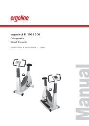
<strong>ergoselect</strong> <strong>100</strong> / <strong>200</strong><br />
Bicycle Ergometer<br />
Operator's Manual<br />
20<strong>100</strong>00134000 • Version 04/2011 • English
This manual was written with the utmost care. Should you still find details that do not correspond with the system,<br />
please let us know and we will correct the issue as soon as possible.<br />
We reserve the right to modify the design and technical features of the device and are not bound by the information and<br />
illustrations provided in this manual.<br />
All trademarks appearing in this document are trademarks of their respective owners. Their protection is acknowledged.<br />
No part of this manual may be reprinted, translated or reproduced without the manufacturer's written permission.<br />
This manual is not subject to any change order service. Please contact the manufacturer for the latest document<br />
revision.<br />
<strong>ergoline</strong> <strong>GmbH</strong><br />
Lindenstraße 5<br />
72475 Bitz<br />
Germany<br />
Tel.: +49-(0) 7431 98 94 - 0<br />
Fax: +49-(0) 7431 98 94 - 128<br />
e-mail: info@<strong>ergoline</strong>.com<br />
http: www.<strong>ergoline</strong>.com<br />
Printed in Germany
Contents<br />
Declaration of Conformity 5<br />
General Information 7<br />
Safety Information 8<br />
Intended Use 9<br />
Setup and Mains Connection 11<br />
Controls and Indicators 11<br />
Transport 12<br />
Setup 12<br />
Mounting the Control Terminal (P or K) 13<br />
Connecting the Power Cord 13<br />
Connecting the Blood Pressure Cuff 16<br />
Transport 16<br />
Preparing the Patient 17<br />
Adjusting the Saddle and the Handlebar 17<br />
Preparing the Patient for Blood Pressure Measurements 18<br />
Checking the Cuff Tubing 19<br />
Operation 21<br />
Control terminal P 21<br />
Turning the System On 21<br />
Operating Modes with Control Terminal P 22<br />
PC Mode 23<br />
Ergometry 24<br />
Manual 26<br />
Settings with Control Terminal P 27<br />
Control Terminal K 32<br />
Turning the System On 32<br />
Operating Modes with Control Terminal K 33<br />
Speed readout 33<br />
PC Mode 34<br />
Ergometry 35<br />
Manual 37<br />
Training 38<br />
Training with Chip Card 39<br />
Settings for Control Terminals K 41<br />
Cleaning, Maintenance, Disposal 48<br />
Technical Specifications 51<br />
Electromagnetic Compatibility EN 60601-1-2 55<br />
- 3 -
- 4 -
DeClaration of Conformity<br />
- 5 -
- 6 -
General information<br />
• The product <strong>ergoselect</strong> bears the CE marking CE‑0123<br />
(Notified Body: TÜV), indicating its compliance with<br />
the provisions of the Council Directive 93/42/EEC<br />
about medical devices and fulfills the essential<br />
requirements of Annex I of this directive.<br />
The CE marking covers only the accessories listed in<br />
the Order Information chapter.<br />
The ergometer is an MDD class IIa product.<br />
• The device fulfills the requirements of standard<br />
EN 60601‑1 "Medical Electrical Equipment, Part 1:<br />
General Requirements for Safety" as well as the<br />
interference protection requirements of standard<br />
EN 60601‑1‑2 "Electromagnetic Compatibility –<br />
Medical Electrical Devices".<br />
The radio‑interference emitted by this product is<br />
within the limits specified in EN 55011, class B.<br />
• This manual is an integral part of the equipment. It<br />
should be available to the equipment operator at all<br />
times. Close observance of the information given in<br />
the manual is a prerequisite for proper device perfor‑<br />
mance and correct operation and ensures patient and<br />
operator safety. Please note that information pertinent<br />
to several chapters is given only once. Therefore, read<br />
the manual once carefully in its entirety.<br />
• The symbols mean:<br />
Consult accompanying documents.<br />
It indicates points which are of particular importance<br />
in the operation of the device.<br />
• Observance of the safety information protects from<br />
injuries and prevents inappropriate use of the device.<br />
All equipment users and persons responsible for<br />
assembly, maintenance, inspection and repair of the<br />
device must read and understand the content of this<br />
manual, before using or work on it.<br />
Paragraphs with special symbols are of particular<br />
importance.<br />
• If unauthorized individuals open the control terminal,<br />
damaging the calibration sticker, any warranty claim<br />
shall become void.<br />
• This manual reflects the equipment specifications<br />
and applicable safety standards valid at the time of<br />
printing. All rights are reserved for devices, circuits,<br />
techniques, software programs, and names appearing<br />
in this manual.<br />
• On request ERGOLINE will provide a Field Service<br />
Manual.<br />
- 7 -<br />
• The ERGOLINE quality management system complies<br />
with the standards ISO 9001: <strong>200</strong>0 and EN ISO 13485:<br />
<strong>200</strong>3.<br />
• The safety information given in this manual is classi‑<br />
fied as follows:<br />
Danger<br />
indicates an imminent hazard. If not avoided, the hazard will<br />
result in death or serious injury.<br />
Warning<br />
indicates a hazard. If not avoided, the hazard may result in<br />
minor injury and/or product/property damage.<br />
Caution<br />
indicates a potential hazard. If not avoided, the hazard may<br />
result in minor injury and/or product/property damage.<br />
• To ensure patient safety, the specified measuring ac‑<br />
curacy, and interference‑free operation, we recom‑<br />
mend using only original ERGOLINE accessories. The<br />
user is responsible if non‑ERGOLINE accessories are<br />
used.<br />
• ERGOLINE is responsible for the safety, reliability, and<br />
performance of the equipment, only if<br />
‑ modifications and repair are carried out by<br />
<strong>ergoline</strong> <strong>GmbH</strong> or by an organization expressly<br />
authorized by <strong>ergoline</strong> <strong>GmbH</strong><br />
‑ the equipment is used in accordance with the<br />
instructions given in this operator's manual.<br />
<strong>ergoline</strong> <strong>GmbH</strong><br />
Lindenstrasse 5<br />
72475 Bitz<br />
Germany<br />
Phone: +49-(0)-7431 - 9894 -0<br />
Fax: +49-(0)-7431 - 9894 -128<br />
e-mail: info@<strong>ergoline</strong> com<br />
http: www <strong>ergoline</strong> com / www <strong>ergoline</strong> eu
safety information<br />
Danger<br />
• Explosion Hazard •<br />
The device is not designed for use in areas where an explosion<br />
hazard may occur.<br />
Explosion hazards may result from the use of flammable anesthetics,<br />
skin cleansing agents or disinfectants.<br />
Warning<br />
• Patient Hazard, Equipment Damage •<br />
Do not expose the <strong>ergoselect</strong> to direct sunlight to prevent system<br />
components from reaching inadmissible high temperatures.<br />
Do NOT use the <strong>ergoselect</strong> outdoors (medical device). Furthermore<br />
the device has no additional protection against the ingress<br />
of humidity. Humidity inside the device may cause equipment<br />
malfunctions and increases the risk of an electric shock.<br />
Additionally, the device should not be operated in the vicinity<br />
of electric power plants, because they may impair equipment<br />
functions.<br />
The <strong>ergoselect</strong> ergometer may only be used in combination with<br />
accessories approved by <strong>ergoline</strong> <strong>GmbH</strong>.<br />
• Risk to Persons •<br />
Before using the ergometer, the operator must ascertain that it is<br />
in correct working order and operating condition. The cables and<br />
connectors, in particular, must be checked for signs of damage.<br />
Damaged parts must be replaced immediately, before use.<br />
• Equipment Malfunction •<br />
Only the special shielded cables supplied by ERGOLINE may be<br />
used to connect the device to other pieces of equipment.<br />
• Equipment Malfunction •<br />
Cellular telephones may not be used in the immediate vicinity<br />
of the ergometer, because they might interfere with the proper<br />
functioning of the ergometer.<br />
Electromagnetic interference most probably exists when the<br />
watt reading is unstable. If the displayed value changes frequently<br />
even though the speed is above 30 RPM, this may be due<br />
to electro magnetic interference.<br />
- 8 -<br />
Warning<br />
• Shock Hazard •<br />
When the ergometer is connected to other equipment or if a<br />
medical system is created, it must be ensured that the added<br />
leakage currents do not present a hazard.<br />
In case of questions, please contact your ERGOLINE dealer or the<br />
<strong>ergoline</strong> <strong>GmbH</strong> Service Department.<br />
For use, the ergometer must always be connected to electric<br />
installations that fulfill the local requirements.<br />
• Patient Hazard •<br />
The German Medical Device Operator Ordinance (MPBetreibV,<br />
§ 5) demands that users<br />
• must be trained in the use of the ergometer<br />
• must be familiar with the routines for handling and<br />
assembly of the ergometer<br />
• must be familiar with and observe the safety rules and<br />
regulations for operation of this type of equipment<br />
• must be informed about any other pertinent rules and regulations<br />
(e.g. safety features)<br />
• must be informed about the potential hazards arising from<br />
the use of this type of equipment.<br />
Hint<br />
Removing the power cord results in complete disconnection<br />
from mains (all poles)..<br />
Danger<br />
Additional equipment connected to medical electrical<br />
equipment must comply with the respective IEC or ISO<br />
standards (e.g. IEC 60950 for data processing equipment).<br />
Furthermore all configurations shall comply with the re‑<br />
quirements for medical electrical systems (see IEC 60601‑<br />
1‑1 or clause 16 of the 3Ed. of IEC 60601‑1, respectively).<br />
Anybody connecting additional equipment to medical<br />
electrical equipment config ures a medical system and is<br />
therefore responsible that the system complies with the<br />
requirements for medical electrical systems. Attention is<br />
drawn to the fact that local laws take priority over the<br />
above mentioned requirements. If in doubt, consult your<br />
local representative or the technical service department.<br />
• IEC 60601‑1+Al +A2:1995: 6.8.2.c, 19.2.b, 19.2.c,<br />
• IEC 60601‑1:<strong>200</strong>5: 7.9.2.5, 8.1, 16.2.d,<br />
• MDD 93142lEEC: Annex I clause 13.6.c
safety information for<br />
non‑invasive BlooD Pressure<br />
measurement<br />
Warning<br />
• Patient Hazard •<br />
Do not take blood pressure measurements with a cuff on<br />
patients suffering from sickle cell anemia or where skin lesions<br />
are likely to occur.<br />
The cuff may cause hematomas in patients with severe blood<br />
coagulation disease. In these instances, the user must take<br />
a decision for or against automatic blood pressure measurements.<br />
Caution<br />
• Compromised Measuring Accuracy •<br />
Arrhythmias occurring frequently during a measurement may<br />
compromise the accuracy of the measurement.<br />
In certain cases, a valid measurement will not be possible.<br />
Electromagnetic fields are also capable of impairing the measuring<br />
accuracy.<br />
Note<br />
• The blood pressure module and the approved accessories<br />
are defibrillation-proof and may remain attached to the<br />
patient during defibrillation.<br />
• If the cuff pressure exceeds the maximum value of<br />
300 mmHg during inflation, the inflation procedure will be<br />
aborted and the cuff deflated.<br />
As a redundant safety precaution, the cuff is immediately<br />
deflated when the cuff pressure exceeds 320 mmHg.<br />
You can check the proper functioning of this safety precaution<br />
by abruptly bending your arm while the cuff is being<br />
inflated, causing a brief overpressure in the cuff. The cuff<br />
must deflate immediately.<br />
• Measurements that did not yield a valid measurement will<br />
not be repeated during the exercise test.<br />
• If the inflation phase takes longer than 40 seconds or if an<br />
adequate pressure does not build up in the cuff within a<br />
reasonable period of time, the measurement will be aborted<br />
and the cuff deflated.<br />
• If a valid measurement cannot be completed within<br />
120 seconds, the measurement will be aborted and the cuff<br />
deflated.<br />
• If the cuff pressure remains constant for some time, the<br />
measurement will also be aborted and the cuff deflated.<br />
- 9 -<br />
intenDeD use<br />
The <strong>ergoselect</strong> is a computer‑controlled medical ergometer.<br />
At pedal speeds between 30 and 130 RPM and loads<br />
between 6 and 999 watt, the ergometer operates indepen‑<br />
dent of the pedal speed.<br />
The speed‑independent range is shown in the Appendix<br />
(Technical Specifications).<br />
The <strong>ergoselect</strong> ergometer may only be used in exercise<br />
testing as well as for rehabilitation of cardiac and cardio‑<br />
vascular patients according to the instructions given in<br />
this manual. If the ergometer is used for other purposes,<br />
the manufacturer cannot be held liable for personal inju‑<br />
ries or property damage resulting from the unintended use<br />
of the equipment.<br />
BioComPatiBility<br />
The parts of the product described in this manual, includ‑<br />
ing all accessories that come in contact with the patient<br />
during the intended use, fulfill the biocompatibility<br />
requirements of the applicable standards if applied as<br />
intended.<br />
If you have questions in this matter, please contact<br />
ERGOLINE or a representative.<br />
aPPliCaBle laws, reGulations anD<br />
DireCtives<br />
• 93/42/EEC (Medical Device Directive of the EU)<br />
• 89/336/EEC (Electromagnetic Compatibility Directive<br />
of the EU)<br />
• EN 1060‑1 Non‑invasive sphygmomanometers, Part 1:<br />
General requirements<br />
• EN 1060‑3 Non‑invasive sphygmomanometers, Part 3:<br />
Supplementary requirements for electro‑mechanical<br />
blood pressure measuring systems
Additional equipment connected to medical electrical<br />
equipment must comply with the respective IEC or ISO<br />
standards (e.g. IEC 60950 for data processing equipment).<br />
Furthermore all configurations shall comply with the re‑<br />
quirements for medical electrical systems (see IEC 60601‑<br />
1‑1 or clause 16 of the 3Ed. of IEC 60601‑1, respectively).<br />
Anybody connecting additional equipment to medical<br />
electrical equipment config ures a medical system and is<br />
therefore responsi ble that the system complies with the<br />
requirements for medical electrical systems. Attention is<br />
drawn to the fact that local laws take priority over the<br />
above mentioned requirements. If in doubt, consult your<br />
local representative or the technical service department.“<br />
(Standard / directive references:<br />
· IEC 60601‑1+Al +A2:1995: 6.8.2.c, 19.2.b, 19.2.c,<br />
· IEC 60601‑1:<strong>200</strong>5: 7.9.2.5, 8.1, 16.2.d,<br />
· MDD 93142lEEC: Annex I clause 13.6.c<br />
- 10 -
setuP anD mains ConneCtion<br />
Controls anD inDiCators<br />
1 Control terminal (model P or model K)<br />
2 Blood pressure cuff connection (option)<br />
3 Adjustment of the handlebar angle<br />
4 Blood pressure cuff<br />
5 Adjustment of the handlebar height<br />
(<strong>ergoselect</strong> <strong>200</strong> only)<br />
6 Castors<br />
7 Speed display (RPM) for patient<br />
8 Adjustment of the saddle height (<strong>ergoselect</strong> <strong>100</strong> only)<br />
9 Digital saddle height indication<br />
(<strong>ergoselect</strong> <strong>200</strong> only)<br />
10 Power switch (green button)<br />
11 Sockets for power cord and connection cables<br />
(underside of ergometer)<br />
12 Levelling devices to adjust the ergometer to uneven<br />
floors<br />
- 11 -<br />
<strong>ergoselect</strong> <strong>100</strong> - controls, connections and indicators<br />
<strong>ergoselect</strong> <strong>200</strong> - controls, connections and indicators
transPort<br />
For short distances, the <strong>ergoselect</strong> can be lifted at the<br />
saddle and rolled away on its castors.<br />
To cover greater distances, however, we recommend the<br />
following method:<br />
• Disconnect the power cord from the wall outlet.<br />
• Rotate the handlebar towards the front.<br />
Tighten the clamping lever.<br />
• Stand in front of the <strong>ergoselect</strong>, grasp the handlebar<br />
and tilt the <strong>ergoselect</strong> towards you until it is standing<br />
on the castors only and is balanced.<br />
• It is now possible to transport the <strong>ergoselect</strong>.<br />
• When you have reached the new location, lower the<br />
<strong>ergoselect</strong> very carefully to avoid damage.<br />
setuP<br />
Place the <strong>ergoselect</strong> on a level floor.<br />
The <strong>ergoselect</strong> must be set up in a secure and stable posi‑<br />
tion ‑ the two levelling feet at the back make for easy<br />
adjustment to uneven floor surfaces. Extend the foot<br />
concerned until the <strong>ergoselect</strong> no longer wobbles.<br />
In case of delicate flooring, it is recommended to place<br />
a mat under the ergometer to protect the flooring from<br />
damage by the feet.<br />
- 12 -<br />
Caution<br />
• Equipment Damage •<br />
Avoid strong vibrations of the <strong>ergoselect</strong> during transport.<br />
transporting the <strong>ergoselect</strong><br />
levelling feet of the <strong>ergoselect</strong> ergometer
mountinG the Control terminal (P or K)<br />
The control terminal can be installed with the display<br />
either facing the patient or the operator.<br />
It is recommended to install the terminal with the display<br />
and control keys towards the operator and the speed<br />
display towards the patient.<br />
ConneCtinG the Power CorD<br />
Set the handlebar to the front upper position and secure.<br />
Tilt the <strong>ergoselect</strong> carefully towards you until it rests on<br />
the handlebar.<br />
- 13 -<br />
different orientations of the control terminal<br />
assembly position of the <strong>ergoselect</strong> ergometer<br />
Caution<br />
• Equipment Damage •<br />
Before connecting the ergometer to the power line, check that<br />
the line voltage corresponds to the ratings on the type plate.<br />
The type plate is located on the back of the ergometer, at the<br />
bottom.
The connection panel is located on the underside of the<br />
ergometer.<br />
• Plug the power cord into socket (a) and use the sup‑<br />
plied lock (b) to secure it against disconnection.<br />
• Using the supplied strain relief, attach the cable to the<br />
metal frame.<br />
- 14 -<br />
connection panel<br />
a Power input<br />
b Lock<br />
power cord with installed strain relief<br />
b<br />
a<br />
Hint<br />
• disconnection •<br />
Removing the power cord results in complete disconnection<br />
from mains (all poles).<br />
Danger<br />
• Patient Hazard •<br />
To insure a safe connection to the protective ground system,<br />
power cords of type „hospital only“ or „hospital grade“ have to<br />
be used!
Connecting the ECG Cable<br />
<strong>ergoselect</strong> ergometers can be connected to electrocardio‑<br />
graphs and PC‑based ECG systems of most manufacturers.<br />
Different connection cables are available to support differ‑<br />
ent communication modes (digital, analog, remote start,<br />
etc.).<br />
The appropriate cable is plugged into the corresponding<br />
socket on the connection panel (Port 1, USB) and secured<br />
with the strain relief.<br />
- 15 -<br />
eKg / pc connection<br />
USB PC connection via USB (virtual COM)<br />
PORT 1 Digital connection RS232 (remote control<br />
by PC or ECG recorder,<br />
Hint<br />
• connecting cables •<br />
Only use connecting cables released by <strong>ergoline</strong>.<br />
To use the integrated USB connector, a special driver is required<br />
- contact <strong>ergoline</strong>.
ConneCtinG the BlooD Pressure Cuff<br />
• Connect the microphone at (1).<br />
• Slip the cuff tubing onto the fitting (2) and engage.<br />
To disconnect, push back the connector's knurled<br />
sleeve.<br />
Artifacts that may be caused by patient movements during<br />
the exercise test, must be avoided if possible, while the<br />
blood pressure is being taken.<br />
Therefore, do not forget to attach the cuff tubing to the<br />
handlebar with the supplied Velcro tape:<br />
• Open the large Velcro tape and wrap around<br />
handlebar.<br />
• Secure the cuff tubing with the small Velcro tape, but<br />
do not exert pressure on the tubing.<br />
transPort<br />
• Disconnect the power cord and the connection cables.<br />
• Stand in front of the ergometer, grasp the handlebar<br />
and tilt the ergometer towards you until it is standing<br />
on the castors only and balanced.<br />
• When you have reached the new location, lower the<br />
ergometer very carefully to avoid damage.<br />
Caution<br />
• Equipment Damage •<br />
Avoid strong vibrations of the ergometer during transport.<br />
- 16 -<br />
blood pressure cuff connections<br />
1 Microphone connection<br />
2 Cuff tubing<br />
velcro tape to secure the cuff tubing
PreParinG the Patient<br />
aDjustinG the saDDle anD the hanDleBar<br />
On the <strong>ergoselect</strong> <strong>100</strong>, you adjust the saddle height manu‑<br />
ally with a clamping lever. On the <strong>ergoselect</strong> <strong>200</strong>, the<br />
saddle height is electrically adjusted with the correspond‑<br />
ing keys on the control terminal (the display below the<br />
saddle indicates the saddle height).<br />
With the pedal in the bottom position, the angle between<br />
the axis formed by the upper body and the thigh should be<br />
approximately 10°.<br />
Set the handlebar to a position where the patient sitting<br />
upright on the saddle can reach it easily.<br />
To do so, open clamping lever 1 and set the handlebar to a<br />
suitable angle.<br />
On the <strong>ergoselect</strong> <strong>200</strong>, the height of the handlebar can ad‑<br />
ditionally be adjusted with clamping lever 2 ‑ the horizon‑<br />
tal bar should be approximately at the samel level as the<br />
saddle.<br />
Note<br />
• Tighten the clamping levers only as far as necessary, NOT<br />
with maximum force.<br />
• Lubricate the clamping lever threads quarterly at minimum,<br />
using a suitable lubricant (e.g. OKS470).<br />
- 17 -<br />
adjusting saddle and handlebar<br />
1 Adjustment of the handlebar angle<br />
2 Adjustment of the handlebar height<br />
(<strong>ergoselect</strong> <strong>200</strong> only)<br />
3 Adjustment of the saddle height (<strong>ergoselect</strong> <strong>100</strong> only)<br />
4 Saddle height display (<strong>ergoselect</strong> <strong>200</strong> only)
PreParinG the Patient for BlooD<br />
Pressure measurements<br />
Cuff size<br />
Always choose the cuff size suitable for the patient's arm.<br />
The maximum arm circumference is indicated on the cuff.<br />
miCroPhone Position<br />
Before applying the cuff, check the position of the micro‑<br />
phone inside the red pocket (on the inside of the cuff):<br />
When the microphone is inside the pocket, its metal side<br />
must face the arm.<br />
aPPlyinG the Cuff<br />
The center of the microphone must be located exactly<br />
on the brachial artery. Locate the artery by palpation, if<br />
required. The red tab identifies the position of the micro‑<br />
phone.<br />
The accurate placement of the microphone is the primary<br />
condition for reliable pressure measurement during exer‑<br />
cise tests.<br />
The cuff must be applied directly on the skin, it may not<br />
be applied on top of clothing, paper, etc. Apply the cuff<br />
approx. 2 cm above the bend of the elbow. The cuff<br />
should be tight, but it should not constrict blood vessels.<br />
The cuff may not move during the exercise test.<br />
- 18 -<br />
correct cuff size<br />
wrong cuff size<br />
correct microphone position<br />
microphone placement on the artery
When you close the Velcro strap, check that the metal<br />
clasp (a) is inside the marked index range (b), and not<br />
outside.<br />
The cuff tab must be located below the metal clasp (see<br />
illustration at right).<br />
CheCKinG the Cuff tuBinG<br />
Check that the cuff tubing does not knock against the<br />
patient's knee, when the patient is pedalling and the hand<br />
is on the handlebar.<br />
Secure the cuff tubing with the Velcro tape attached to the<br />
handlebar.<br />
Instruct your patient to move as little as possible during<br />
a blood pressure measurement and, in particular, to avoid<br />
excessive contractions of the muscles in the upper arm.<br />
Caution<br />
• Patient Hazard •<br />
Apply the cuff directly on the skin. Make sure that rolled up<br />
sleeves do not impede blood circulation in the upper arm.<br />
Loose cuffs will cause erroneous measurements; overtight cuffs<br />
may constrict blood vessels or cause skin lesions and hematomas.<br />
• Incorrect Measurements •<br />
A loose cuff would degrade the accuracy of the measurement.<br />
Therefore, the computer aborts the measurement, if a minimum<br />
pressure is not attained within a few seconds.<br />
- 19 -<br />
correct cuff position (tab)<br />
distance between Knee and tubing<br />
Warning<br />
• Patient Hazard •<br />
If, by accident, an excessive pressure builds up inside the cuff ,<br />
either remove the cuff immediately from the arm or disconnect<br />
the cuff tubing from the control terminal.<br />
The same measures are recommended, if the cuff does not<br />
deflate correctly.
- 20 -
oPeration<br />
The ergometers of the <strong>ergoselect</strong> series are available with<br />
two versions of the control terminal whose functionalities<br />
differ.<br />
The following sections describe the control and configura‑<br />
tion of the ergometer.<br />
Control terminal P<br />
turninG the system on<br />
You turn the ergometer on by pressing the power switch ‑<br />
the green indicator in the switch lights up.<br />
The ergometer runs a self‑test. Subsequently, the main<br />
menu displays.<br />
Note<br />
• Instruct the patient not to pedal while the ergometer is<br />
being turned on and during the self-test.<br />
• Apply the blood pressure cuff to the patient AFTER the ergometer<br />
has been turned on and the self-test completed.<br />
• The device can be configured to default to one of the<br />
operating modes.<br />
If this option is selected, the initial screen of the selected<br />
operating mode (e.g. Ergometry) will be displayed instead<br />
of the main menu.<br />
With the key, you can display the main menu.<br />
• If an error message (e.g. E:01) appears immediately after<br />
the self-test, please refer to the "Troubleshooting" section<br />
for advice.<br />
The ergometer software is controlled with 5 keys:<br />
With this key you display the main menu or<br />
return to the previous menu level.<br />
With this key you initiate a blood pressure mea‑<br />
surement. A measurement in progress can be aborted with<br />
the same key.<br />
The functions of these three softkeys<br />
change with the displayed menu ‑ the key label describing<br />
the function is shown on the display.<br />
- 21 -<br />
Control terminal P Control terminal K<br />
self-test screen<br />
main menu<br />
<strong>ergoline</strong><br />
<strong>GmbH</strong><br />
PC Mode<br />
Ergometry<br />
Manual<br />
Settings<br />
Keypad p<br />
Selftest running<br />
Select
oPeratinG moDes with Control terminal<br />
P<br />
An <strong>ergoselect</strong> ergometer with a control terminal P sup‑<br />
ports the following operating modes:<br />
PC MODE<br />
An external device (e.g. stand‑alone electrocardio‑<br />
graph, PC‑based ECG system) controls the ergometer ‑<br />
no intervention at all is required at the ergometer.<br />
ERGOMETRY<br />
The ergometer runs an automatic exercise test ‑ some<br />
of the corresponding test protocols are user‑configu‑<br />
rable and stored in the system (see chapter "Settings").<br />
MANUAL<br />
The ergometer is controlled manually, i.e., the user<br />
performs all load changes via the keypad.<br />
SETTINGS<br />
Used to configure the ergometer.<br />
sPeeD reaDout<br />
At the top of the control terminal, there is a speed readout<br />
for the patient as well as three LEDs that inform the<br />
patient of the speed: too slow, too fast or correct.<br />
The ranges for the respective speed ratings depend on the<br />
selected load (see "Technical Specifications"). speed readout<br />
1 speed low (patient should pedal faster)<br />
2 correct speed<br />
3 speed high (= patient should pedal slower)<br />
Note<br />
• If, during an exercise test, the speed drops below 30 RPM,<br />
the load readout starts blinking on the display.<br />
• To reactivate the saddle height adjustment function, press<br />
and the arrow keys will again be displayed.<br />
• Additional blood pressure measurements an be initiated<br />
with .<br />
- 22 -
PC moDe<br />
Use the softkeys on the right and left (↑ ↓) to position the<br />
bar cursor on PC MODE and confirm the selection with<br />
SELECT.<br />
The display changes ‑ the ergometer is waiting for com‑<br />
mands from the external ECG unit.<br />
With the arrrow keys, the saddle height can be electrically<br />
adjusted on the <strong>ergoselect</strong> <strong>200</strong> (on the <strong>ergoselect</strong> 400,<br />
these keys adjust the height of the drive unit).<br />
As soon as the ergometer receives commands from the<br />
controlling ECG unit or PC, the exercise test will start and<br />
the corresponding values will be displayed.<br />
The exercise test can only be terminated with the corre‑<br />
sponding command from the controlling ECG unit.<br />
Note<br />
• All functions are locked while the ergometer is operating<br />
in PC mode, except for the saddle height adjustment and<br />
the blood pressure key .<br />
• To reactivate the saddle height adjustment function, press<br />
and the arrow keys will again be displayed.<br />
• Additional blood pressure measurements can be initiated<br />
with .<br />
- 23 -<br />
PC Mode<br />
Ergometry<br />
Manual<br />
Settings<br />
↑ ↓<br />
Select<br />
main menu<br />
initial screen<br />
Saddle<br />
PC Mode<br />
display during exercise test<br />
1 current load in watts<br />
2 most recent BP value (systolic/diastolic values) or cuff<br />
pressure during inflation<br />
3 duration of exercise test (min)<br />
4 heart rate at the time of the BP measurement (BPM)<br />
5 pedal speed (RPM)
erGometry<br />
Use the softkeys on the right and left (↑ ↓) to position the<br />
bar cursor on ERGOMETRY and confirm the selection with<br />
SELECT.<br />
The stored test protocols available for selection will be<br />
displayed. There are five fixed protocols (protocols 1 to 5,<br />
see Appendix) , whereas protocols 6 to 15 are user‑pro‑<br />
grammable.<br />
The protocol menu provides an overview of the test<br />
phases:<br />
e.g.: 50 W / 2 min / 25 W<br />
means: initial (basic) load 50 watts<br />
stage time 2 minutes<br />
load increment 25 watts<br />
Use the softkeys on the right and left (↑ ↓) to position the<br />
bar cursor on one of the protocols and confirm the selec‑<br />
tion with SELECT.<br />
The exercise test is started with the "Start" key, a blood<br />
pressure measurement at rest may precede the test (see<br />
"Settings").<br />
When the basic load appears on the display (after approx.<br />
15 seconds or upon termination of the blood pressure<br />
measurement) and the patient's RPM indicator blinks, the<br />
patient should start pedalling.<br />
The internal protocol will now control the entire exercise<br />
test ‑ the display always indicates the current values.<br />
With the +5 W and ‑5 W keys, the current load can be<br />
changed at any time (in increments of +/‑1 W up to<br />
+/‑25 W, as configured).<br />
- 24 -<br />
PC Mode<br />
Ergometry<br />
Manual<br />
Settings<br />
main menu<br />
Select<br />
Protocols<br />
1. WHO<br />
2. BAL<br />
3. Hollmann<br />
4. STD. France<br />
5. Standard<br />
Select<br />
selecting an exercise test protocol<br />
initial exercise test screen<br />
Start<br />
+ 5 W Recovery<br />
- 5 W<br />
screen display during the test
Note<br />
• The saddle height (<strong>ergoselect</strong> <strong>200</strong>) can be changed during<br />
an exercise test.<br />
• To reactivate the saddle height adjustment function, press<br />
and the arrow keys will again be displayed.<br />
• Additional blood pressure measurements can be initiated<br />
with .<br />
terminatinG an exerCise test<br />
The exercise phase can be terminated manually at any time<br />
with the RECOVERY key.<br />
The load will immediately be reduced to 25 watts, but a<br />
higher or lower value can be selected manually.<br />
It is recommended that the patient continues to pedal in<br />
the recovery phase.<br />
The END key in the middle will terminate the test.<br />
- 25 -<br />
+ 5 W End - 5 W<br />
recovery phase
manual<br />
Use the softkeys on the right and left (↑ ↓) to position the<br />
bar cursor on MANUAL and confirm the selection with<br />
SELECT.<br />
In this operating mode the user controls the entire exercise<br />
test by selecting the loads, stage times and by initiating<br />
blood pressure measurements.<br />
The exercise test is started with the "Start" key, afterwards<br />
the load can be set and changed with the +5 W and ‑5 W<br />
keys (in increments of +/‑1 W up to +/‑25 W, as config‑<br />
ured).<br />
Blood pressure measurements an be initiated with .<br />
terminatinG an exerCise test<br />
The exercise test can be terminated manually at any time<br />
with the END key located in the middle.<br />
The load will immediately drop to 0 watt.<br />
There is no recovery phase in the manual mode.<br />
- 26 -<br />
PC Mode<br />
Ergometry<br />
Manual<br />
Settings<br />
main menu<br />
Select<br />
+ 5 W Start - 5 W<br />
initial screen of a manual exercise test<br />
+ 5 W End<br />
- 5 W<br />
screen display during the test
settinGs with Control terminal P<br />
Some of the device settings are configurable to meet spe‑<br />
cific requirements. The settings will be saved and remain<br />
stored even when the ergometer is switched off.<br />
Use the softkeys on the right and left (↑ ↓) to position the<br />
bar cursor on SETTINGS and confirm the selection with<br />
SELECT.<br />
The configuration menu displays.<br />
When all changes have been made, you can exit the con‑<br />
figuration menu with the key.<br />
Use the softkeys on the right and left (↑ ↓) to position the<br />
bar cursor on the parameter to change and confirm the<br />
selection with SELECT.<br />
Default moDe<br />
In this menu you choose the default mode activated when<br />
the ergometer is turned on. When first turned on, the<br />
ergometer will display this menu.<br />
Use the softkeys on the right and left (↑ ↓) to position the<br />
bar cursor on your preferred default mode and save the<br />
selection with SELECT.<br />
ProtoCols<br />
Protocols 6 ‑ 15 are user‑programmable (protocols 1 ‑ 5<br />
are fixed, see Appendix for protocol parameter details).<br />
Standard values for the following parameters can be<br />
entered:<br />
‑ initial load<br />
‑ stage time<br />
‑ load increment (load increase with each stage)<br />
Use the softkeys on the right and left (↑ ↓) to position<br />
the bar cursor on the protocol to change (No. 6 ‑ 15) and<br />
confirm the selection with SELECT.<br />
- 27 -<br />
PC Mode<br />
Ergometry<br />
Manual<br />
Settings<br />
main menu<br />
configuration menu<br />
Select<br />
Settings<br />
Default Mode<br />
Protocols<br />
Contrast<br />
Load Change<br />
Language<br />
Select<br />
Default Mode<br />
Menu<br />
PC Mode<br />
Ergometry<br />
Manual<br />
selecting the default mode<br />
Select<br />
Protocols<br />
1. WHO<br />
2. BAL<br />
3. Hollmann<br />
4. STD. France<br />
5. Standard<br />
Select<br />
selecting the exercise test protocol to edit
Use the right and left softkeys ↑ ↓ to select the parameter<br />
to edit.<br />
When confirmed with SELECT, the corresponding value ap‑<br />
pears in reverse video and can be changed with the arrow<br />
keys ↑ ↓.<br />
Pressing SELECT will save the new value.<br />
All other parameters are edited in the same way.<br />
You exit the configuration with .<br />
Contrast<br />
The display contrast is adjustable in the range from<br />
0 to <strong>100</strong>%.<br />
loaD ChanGe<br />
Here you determine the increments for each load change.<br />
Depending on your choice, each key press will change the<br />
load by +/‑ 1, 5, 10 und 20 Watts.<br />
- 28 -<br />
Protocol<br />
6.<br />
Basic Load 25 W<br />
Stage Time 2 min<br />
Load Stage 25 W<br />
Select<br />
selecting the parameter to edit<br />
Protocol<br />
6.<br />
Basic Load 25 W<br />
Stage Time 2 min<br />
Load Stage 25 W<br />
Select<br />
editing the parameter value<br />
Contrast<br />
50 %<br />
Select<br />
adjusting the display contrast<br />
Load Change<br />
+/- 1 Watt<br />
+/- 5 Watt<br />
+/- 10 Watt<br />
+/- 25 Watt<br />
Select<br />
selecting the increment for manual load changes
lanGuaGe<br />
The texts can be displayed in different<br />
languages.<br />
BeeP<br />
The audio signal emitted during blood pressure measure‑<br />
ments can be turned on and off.<br />
software version<br />
Select this option to view the installed software version.<br />
Date/time<br />
To begin with, you select DATE or TIME and confirm the<br />
selection. Then the value displayed in reverse video can be<br />
edited with the ↑ ↓ keys and saved with SELECT.<br />
The time is adjusted in the same way.<br />
You exit the configuration with .<br />
- 29 -<br />
Language<br />
Deutsch<br />
English<br />
Francais<br />
Espanol<br />
Italiano<br />
language menu<br />
Beep<br />
Auswahl<br />
On<br />
Off<br />
Select<br />
beep during bp measurements<br />
Date<br />
Time<br />
setting the date<br />
Date<br />
Time<br />
setting the day<br />
22. 08. <strong>200</strong>7<br />
17 : 33 : 05<br />
Select<br />
22. 08. <strong>200</strong>7<br />
17 : 33 : 05<br />
Select
eKG tyPe<br />
The selected EKG Type determines the communication<br />
method with the ECG recorder, PC‑based ECG system, etc.<br />
To prevent an accidental change of this setting, the menu<br />
is protected with a password.<br />
Using the arrow keys, enter 003 and confirm the entry<br />
with SELECT.<br />
All <strong>ergoselect</strong> ergometers support the following communi‑<br />
cation modes:<br />
• Analog with pulse<br />
Remote start mode; prior the each load change, the<br />
ergometer generates a control pulse and sends the<br />
corresponding data via the interface.<br />
• Analog / Digital<br />
An analog voltage controls the load ‑ blood pressure<br />
measurements can be initiated with digital commands.<br />
• Digital (default)<br />
The communication with the ergometer is entirely<br />
controlled with digital commands.<br />
• Analog IN‑OUT<br />
The entire communication (load control and BP mea‑<br />
surements) is controlled with analog signals.<br />
No digital data will be sent.<br />
Select the communication mode and confirm with SELECT.<br />
Note<br />
• The EKG Type needs to be selected only when the ergometer<br />
is connected to an ECG unit. The selection is part of<br />
the installation procedure.<br />
• The "Analog/Digital" and "Digital" communication is only<br />
possible when PC Mode is selected from the main menu or<br />
when this is the default mode.<br />
- 30 -<br />
EKG Type<br />
003<br />
Select<br />
entering the eKg type password<br />
EKG Type<br />
Analog with pulse<br />
Analog / Digital<br />
Digital<br />
Analog IN-OUT<br />
Select<br />
selecting the ergometer communication mode
Pm<br />
Here you determine the RPM limits. When these limits<br />
are exceeded, the LEDs for high or low speed (RPM) will<br />
illuminate.<br />
Select the value to change (Min. or Max.) and confirm with<br />
SELECT.<br />
Using the arrow keys, change the value and save the new<br />
value with SELECT.<br />
Note<br />
• The limits selected in this menu only apply to the load<br />
range between 6 and 150 watts. At higher loads the RPM<br />
limits automatically adapt to the respective loads:<br />
Load (watts) Green RPM range (1/min)<br />
6 - 150 54 - 64 (adjustable)<br />
151 - 250 58 - 65<br />
251 - 350 68 - 75<br />
351 - 450 78 - 85<br />
451 - 550 88 - 95<br />
551 - 650 98 - 105<br />
651 - 750 108 - 115<br />
751 - 850 118 - 125<br />
851 - 950 > 125<br />
951 - 999 > 130<br />
Pulse DisPlay<br />
The pulse readout on the display can be turned off.<br />
- 31 -<br />
RPM<br />
Min ↑ 0 ... 70<br />
54<br />
Max. ↓ 50 ... 130<br />
64<br />
Select<br />
setting the rpm limit values
Control terminal K<br />
turninG the system on<br />
You turn the ergometer on by pressing the power switch ‑<br />
the green indicator in the switch lights up.<br />
The ergometer runs a self‑test. Subsequently, the main<br />
menu displays.<br />
Note<br />
• Instruct the patient not to pedal while the ergometer is<br />
being turned on and during the self-test.<br />
• Apply the blood pressure cuff to the patient AFTER the<br />
ergometer has been turned on and the self-test been<br />
completed.<br />
• The device may be configured to default to one of the<br />
operating modes.<br />
If this option is selected, the initial screen of the selected<br />
operating mode (e.g. Ergometry) will be displayed instead<br />
of the main menu.<br />
With the key, you can display the main menu.<br />
• If an error message (e.g. E:01) appears immediately after<br />
the self-test, please refer to the "Troubleshooting" section<br />
for advice.<br />
The ergometer software is controlled with 8 keys:<br />
With this key you display the main menu or<br />
return to the previous menu level.<br />
With this key you initiate a blood pressure mea‑<br />
surement. A measurement in progress can be aborted with<br />
the same key.<br />
The functions of these six softkeys<br />
change with the displayed menu ‑ the<br />
key label describing the function is<br />
shown on the display.<br />
- 32 -<br />
self-test screen<br />
main menu<br />
Keypad K<br />
<strong>ergoline</strong><br />
<strong>GmbH</strong><br />
Selftest running<br />
Exercise Test PC Mode<br />
Training Manual<br />
Test Settings
oPeratinG moDes with Control terminal<br />
K<br />
An <strong>ergoselect</strong> ergometer with a control terminal K sup‑<br />
ports the following operating modes:<br />
PC MODE<br />
An external device (e.g. stand‑alone electrocardio‑<br />
graph, PC‑based ECG system) controls the ergometer ‑<br />
no intervention at all is required at the ergometer.<br />
ERGOMETRY<br />
The ergometer runs an automatic exercise test ‑ some<br />
of the corresponding test protocols are user‑configu‑<br />
rable and stored in the system (see chapter "Settings").<br />
TRAINING<br />
Ten different training protocols with warm‑up, exer‑<br />
cise and recovery phases can be custom‑configured<br />
(see chapter "Settings").<br />
A POLAR receiver is integrated in the ergometer and<br />
provides the relevant data for heart‑rate controlled<br />
sPeeD reaDout<br />
At the top of the control terminal, there is a speed readout<br />
for the patient as well as three LEDs that inform the<br />
patient of the speed: too slow, too fast or correct.<br />
The ranges for the respective speed ratings depend on the<br />
selected load (see "Technical Specifications").<br />
Note<br />
• If, during an exercise test, the speed drops below 30 RPM,<br />
the load readout starts blinking on the display.<br />
• To reactivate the saddle height adjustment function, press<br />
and the arrow keys will again be displayed.<br />
• Additional blood pressure measurements can be initiated<br />
with .<br />
- 33 -<br />
training sessions.<br />
TEST<br />
Integrated test protocols (steep ramping test, PWC<br />
tests) allow an assessment of the physical fitness.<br />
MANUAL<br />
The ergometer is controlled manually, i.e., the user<br />
performs all load changes via the keypad.<br />
SETTINGS<br />
Used to configure the ergometer.<br />
speed readout<br />
1 speed low (patient should pedal faster)<br />
2 correct speed<br />
3 speed high (= patient should pedal slower)
PC moDe<br />
When the PC Mode key has been pressed, the screen<br />
appears as shown at right. The ergometer is waiting for<br />
commands from the external ECG unit.<br />
With the arrrow keys, the saddle height can be electrically<br />
adjusted on the <strong>ergoselect</strong> <strong>200</strong> (on the <strong>ergoselect</strong> 400,<br />
these key adjust the height of the drive unit).<br />
As soon as the ergometer receives commands from the<br />
controlling ECG unit or PC, the exercise test will start and<br />
the corresponding values will be displayed.<br />
The exercise test can only be terminated with the corre‑<br />
sponding command from the controlling ECG unit.<br />
Note<br />
• All functions are locked while the ergometer is operating<br />
in PC mode, except for the saddle height adjustment and<br />
the blood pressure key .<br />
• To reactivate the saddle height adjustment function, press<br />
and the arrow keys will again be displayed.<br />
• Additional blood pressure measurements can be initiated<br />
with .<br />
• Changing the display mode:<br />
Instead of the waveforms, the individual parameter values<br />
can be displayed at a large scale.<br />
With the key, you display the menu; with the key<br />
at the bottom right, you select the DISPLAY. The blood<br />
pressure values will now be displayed with large digits.<br />
With each subsequent activation of the key at the bottom<br />
right you scroll through the following values:<br />
- heart rate<br />
- test duration<br />
- load (Watt)<br />
- RPM<br />
- graphic display<br />
- 34 -<br />
PC Mode: Waiting for start<br />
initial screen in pc mode<br />
Exercise test running<br />
Saddle<br />
Saddle<br />
↑<br />
12<br />
↓<br />
display during exercise test<br />
1 most recent BP value (systolic/diastolic pressures) or cuff<br />
pressure during inflation<br />
2 heart rate (BPM)<br />
3 duration of exercise test (minutes:seconds)<br />
4 current load in watts<br />
5 pedal speed (RPM)<br />
Exercise test running<br />
bp displayed with large digits
erGometry<br />
The ergometer is controlled by an internally stored proto‑<br />
col.<br />
Pressing the "Ergometry" key will display the test protocol<br />
used last.<br />
Press the "Start" key to re‑start the protocol, or press the<br />
"Select" key to display the protocol parameters or to switch<br />
to another test protocol.<br />
There are five fixed protocols (protocols 1 ‑ 5, see<br />
Appendix), whereas protocols 6 ‑ 15 are user‑program‑<br />
mable.<br />
With the arrow keys you can display the test protocol.<br />
With "Select" you confirm the selection.<br />
The selected exercise test is started with the "Start" key, a<br />
blood pressure measurement at rest may precede the test<br />
(see "Settings").<br />
The display changes to the exercise test screen, where load<br />
and heart rate are represented both by numeric values and<br />
waveforms.<br />
When the basic load appears on the display (after approx.<br />
15 seconds or upon termination of the blood pressure<br />
measurement) and the patient's RPM indicator blinks, the<br />
patient should start pedalling.<br />
The internal protocol will now control the entire exercise<br />
test ‑ the display always indicates the current values.<br />
- 35 -<br />
Ergometry WHO<br />
initial screen of an exercise test<br />
Saddle ↑<br />
12<br />
Saddle ↓<br />
Start Select<br />
Protocol WHO<br />
Make settings<br />
Basic Load 25 Watt<br />
Stage Time 2 min<br />
Load Stage 25 Watt<br />
Recovery Load 25 Watt<br />
Recovery Time 10 min<br />
NIBP Lead Time 60 sec<br />
Select protocol<br />
selecting the test protocol<br />
Exercise test running<br />
↑<br />
↓<br />
Select<br />
display during exercise test<br />
1 most recent BP value (systolic/diastolic pressures) or cuff<br />
pressure during inflation<br />
2 heart rate (BPM)<br />
3 duration of exercise test (minutes:seconds)<br />
4 current load in watts<br />
5 pedal speed (RPM)
aDjustments DurinG the exerCise test<br />
Press the key to display the configuration menu.<br />
This is what you can do during the test<br />
• increase or decrease the current load in increments<br />
(adjustable between 1 watt and 25 watts)<br />
• hold the current load<br />
• end the exercise phase and advance to the recovery<br />
phase<br />
• terminate the test.<br />
Pressing again displays another menu where you<br />
can change the saddle height and the display mode (see<br />
"PC Mode").<br />
terminatinG the test<br />
Once the full protocol has been completed, the test will be<br />
terminated.<br />
However, it is possible at any time to manually terminate<br />
the test or switch to the recovery phase (see above).<br />
- 36 -<br />
Load + Recovery phase<br />
Load - End<br />
Load const. Previous<br />
configuration menu i<br />
configuration menu ii<br />
Make settings<br />
Saddle ↑<br />
12<br />
Saddle ↓<br />
Previous Display<br />
Make settings
manual<br />
In this operating mode the user controls the entire exercise<br />
test by selecting the loads, stage times and by initiating<br />
blood pressure measurements.<br />
The exercise test is started with the "Start" key, afterwards<br />
the load can be set and changed with the [Load +] and<br />
[Load +] keys (in increments of 1 W up to 25 W, as config‑<br />
ured).<br />
Blood pressure measurements can be initiated with .<br />
terminatinG an exerCise test<br />
The exercise test can be terminated manually at any time<br />
with the END key located in the middle.<br />
The load will immediately drop to 0 watt.<br />
There is no recovery phase in the manual mode.<br />
- 37 -<br />
Load + Saddle ↑<br />
12<br />
Load - Saddle ↓<br />
Start<br />
Ergometry: Waiting for start<br />
screen display in manual mode
traininG<br />
Cardiologic training sessions can be performed with er‑<br />
goselect ergometers equipped with control terminal K.<br />
For a detailed description of the protocols, please refer to<br />
the Appendix.<br />
Pressing the "Training" key will display the training proto‑<br />
col used last.<br />
Press the "Start" key to re‑start the protocol, or press the<br />
"Select" key to display the protocol parameters or to switch<br />
to another training protocol.<br />
All training protocols 1 ‑ 10 are user‑configurable. (see<br />
"Settings for Control Terminals K").<br />
Use the arrow keys to display the protocol to use and the<br />
corresponding parameters. Confirm the selection with the<br />
"Select" key.<br />
You initiate the training session with the "Start" key.<br />
The display changes to the training session screen, where<br />
load and heart rate are represented both by numeric values<br />
and by waveforms.<br />
When the basic load appears on the display (after approx.<br />
15 seconds or upon termination of the blood pressure<br />
measurement) and the patient's RPM indicator blinks, the<br />
patient should start pedalling.<br />
The internal protocol will now control the entire training<br />
session ‑ the display always indicates the current values.<br />
- 38 -<br />
Training No.1 Pulse<br />
initial screen of the training session<br />
Saddle ↑<br />
12<br />
Saddle ↓<br />
Start Select<br />
Make settings<br />
Training No. 1 Pulse<br />
Basic Load 25 Watt<br />
Warmup 2 min<br />
Training time 20 min<br />
Recovery Load 20 Watt<br />
Recovery Time 3 Watt<br />
Load increment 8 Watt/min<br />
Training pulse <strong>100</strong> P/min<br />
Maximum load 80 Watt<br />
Select protocol<br />
Select<br />
selecting the training protocol<br />
Training running<br />
display during exercise test<br />
1 most recent BP value (systolic/diastolic pressures) or cuff<br />
pressure during inflation<br />
2 heart rate (BPM)<br />
3 duration of exercise test (minutes:seconds)<br />
4 current load in watts<br />
5 pedal speed (RPM)<br />
↑<br />
↓
aDjustments DurinG the traininG session<br />
Press the key to display the configuration menu.<br />
This is what you can do during the training session<br />
• end the training session and advance to the recovery<br />
phase,<br />
• directly terminate the training session,<br />
• change the display mode (see "PC Mode").<br />
traininG with ChiP CarD<br />
As an alternative to the training protocols saved in the<br />
ergometer, it is possible to load training protocols from the<br />
chip card.<br />
The training protocols are saved to the chip card by means<br />
of a PC program ("<strong>ergoline</strong> opticare professional" or "ergo‑<br />
line opticare basic").<br />
Upon completion of the training session, the entire proce‑<br />
dure (incl. load and heart rate waveforms) is saved to the<br />
chip card and can be reviewed and analyzed at the PC.<br />
startinG the ChiP CarD traininG session<br />
Select the "Training" mode and insert the chip card into<br />
the card reader (on the side of the control terminal).<br />
The ergometer switches to the chip card mode and reads<br />
the data stored on the card.<br />
- 39 -<br />
Recovery phase<br />
End<br />
Previous Display<br />
configuration menu<br />
Training Chipcard<br />
Reading card!<br />
Training running<br />
reading the chip card data
The name and the weight stored on the card are displayed.<br />
You can use the arrow keys to enter the current weight.<br />
Press the "Next" key and the initial screen will display.<br />
You can initiate the displayed training protocol or select<br />
another protocol from the chip card.<br />
The chip card training session proceeds in the same way as<br />
the exercise tests stored in the ergometer.<br />
terminatinG the traininG session<br />
After termination of the training session (automatic ter‑<br />
mination when the programmed recovery phase has been<br />
completed, or manual termination) the test subject can<br />
state how the test was perceived (BORG scale).<br />
Subsequently all training data are written to the chip card<br />
and are then available for analysis with a special program<br />
(e.g. opticare basic).<br />
- 40 -<br />
Training Chipcard<br />
Sumner<br />
David<br />
Weight +<br />
93 kg<br />
Weight -<br />
Next<br />
entering the weight<br />
Training Chipcard<br />
entering the borg value<br />
Make settings<br />
Stress<br />
very very heavy<br />
↑<br />
very heavy<br />
heavy<br />
a little stronger<br />
↓<br />
easy<br />
very easy<br />
very very easy OK<br />
Training Chipcard<br />
Sumner<br />
David<br />
Training finished !<br />
Writing card!<br />
writing to the chip card
settinGs for Control terminals K<br />
Some of the device settings are configurable to meet spe‑<br />
cific requirements. The settings will be saved and remain<br />
stored even when the ergometer is switched off.<br />
Select SETTINGS to display the configuration menu.<br />
When all changes have been made, you can exit the con‑<br />
figuration menu with the key.<br />
Use the softkeys (↑ ↓) to position the bar cursor on the pa‑<br />
rameter to change and confirm the selection with SELECT.<br />
Default moDe<br />
In this menu you choose the default mode activated when<br />
the ergometer is turned on. When first turned on, the<br />
ergometer will display this menu.<br />
Use the softkeys (↑ ↓) to position the bar cursor on your<br />
preferred default mode and save the selection with SELECT.<br />
ProtoCols<br />
Protocols 6 ‑ 15 are user‑programmable (protocols 1 ‑ 5<br />
are fixed, see Appendix for protocol parameter details).<br />
Standard values for the following parameters can be<br />
entered:<br />
‑ initial load<br />
‑ stage time<br />
‑ load increment (load increase with each stage)<br />
‑ NIBP lead time (blood pressure measurement)<br />
‑ recovery load<br />
‑ recovery time<br />
Use the softkeys (↑ ↓) to position the bar cursor on the<br />
protocol to change (No. 6 ‑ 15) and confirm the selection<br />
with SELECT.<br />
- 41 -<br />
Settings<br />
Default Mode<br />
Protocols<br />
Contrast<br />
↑<br />
Load Change<br />
Language<br />
Beep<br />
↓<br />
Software Version<br />
Date/Time<br />
Training Select<br />
EKG Type<br />
Choose function<br />
configuration menu<br />
Protocols<br />
1. WHO<br />
2. BAL<br />
3. Hollmann<br />
↑<br />
4. STD. France<br />
5. Standard<br />
6. 25W / 2min / 25W<br />
↓<br />
7. 25W / 2min / 25W<br />
8. 25W / 2min / 25W<br />
9. 25W / 2min / 25W Select<br />
10. 25W / 2min / 25W<br />
Choose function<br />
selecting the exercise test protocol to edit
Use the softkeys ↑ ↓ to select the parameter to edit.<br />
When confirmed with SELECT, the corresponding value ap‑<br />
pears in reverse video and can be changed with the arrow<br />
keys ↑ ↓.<br />
Pressing SELECT will save the new value.<br />
All other parameters are edited in the same way.<br />
You exit the configuration with .<br />
Contrast<br />
The display contrast is adjustable in the range from<br />
0 to <strong>100</strong>%.<br />
- 42 -<br />
Protocol 6.<br />
Basic Load 25 Watt<br />
Stage Time 2 min ↑<br />
Load Stage 25 Watt<br />
NIBP Lead Time 60<br />
Recovery Load 25<br />
sec<br />
Watt<br />
↓<br />
Recovery Time 2 min Select<br />
Choose function<br />
selecting the parameter to edit<br />
Protocol 6.<br />
Basic Load 25 Watt<br />
Stage Time 2 min ↑<br />
Load Stage 25 Watt<br />
NIBP Lead Time 60<br />
Recovery Load 25<br />
sec<br />
Watt<br />
↓<br />
Recovery Time 2 min Select<br />
editing the parameter value<br />
Contrast<br />
Choose function<br />
50 %<br />
Choose function<br />
editing the parameter value<br />
Select<br />
↑<br />
↓
loaD ChanGe<br />
Here you determine the increments for each load change.<br />
Depending on your choice, each key press will change the<br />
load by +/‑ 1, 5, 10 und 20 watts.<br />
lanGuaGe<br />
The texts can be displayed in different languages.<br />
BeeP<br />
The audio signal emitted during blood pressure measure‑<br />
ments can be turned on and off.<br />
software version<br />
Select this option to view the ergometer's installed soft‑<br />
ware version.<br />
- 43 -<br />
Load Change<br />
+/- 1 Watt<br />
+/- 5 Watt<br />
+/- 10 Watt<br />
+/- 25 Watt<br />
↑<br />
↓<br />
Select<br />
selecting the increment for manual load changes<br />
Language<br />
Deutscht<br />
English<br />
Francais<br />
IBP-Espanol<br />
Italiano<br />
language menu<br />
Choose function<br />
↑<br />
↓<br />
Select
Date/time<br />
To begin with, you select DATE or TIME and confirm the<br />
selection.<br />
Then the value displayed in reverse video can be edited<br />
with the ↑ ↓ keys and saved with SELECT.<br />
The time is set in the same way.<br />
You exit the configuration with .<br />
traininG<br />
Ten training protocols consisting of warmup, training and<br />
recovery phase are user‑configurable. Depending on the<br />
selected training mode (pulse, constant, interval), there will<br />
be different parameters to define for the training phase:<br />
First of all you select and confirm the protocol you wish to<br />
configure.<br />
Then you select the parameters with the arrow keys (↑ ↓)<br />
as usual and edit them.<br />
- 44 -<br />
Date/Time<br />
Date<br />
22. 08. <strong>200</strong>7<br />
Time<br />
17 : 33: 51<br />
setting the date<br />
Date/Time<br />
Date<br />
22. 08. <strong>200</strong>7<br />
Time<br />
17 : 33: 51<br />
changing the date<br />
Choose function<br />
Choose function<br />
selecting the exercise test protocol to edit<br />
↑<br />
↓<br />
Select<br />
↑<br />
↓<br />
Select<br />
Training<br />
1. Pulse<br />
2. Constant<br />
3. Interval<br />
↑<br />
4. Interval<br />
5. Pulse<br />
6. Pulse<br />
↓<br />
7. Pulse<br />
8. Pulse<br />
9. Pulse Select<br />
10. Pulse<br />
Choose function
For all training modes (pulse, constant load and interval),<br />
the warmup phase, the duration of the training session<br />
and the recovery phase are defined first.<br />
Depending on the selected training mode, you can edit the<br />
corresponding parameters afterwards:<br />
• Pulse-controlled training:<br />
Training pulse: 40 ‑ 250 1/min<br />
Maximum load: 1 ‑ 999 Watt<br />
• Constant load:<br />
Training load: 1 ‑ 999 Watt<br />
• Interval training:<br />
Load Stage 1: 1 ‑ 999 Watt<br />
Stage Time 1: 10 ‑ 300 sec<br />
Load Stage 2: 1 ‑ 999 Watt<br />
Stage Time 2: 10 ‑ 300 sec<br />
- 45 -<br />
Training<br />
Select Pulse<br />
Basic Load 20 Watt<br />
Warmup 2 min ↑<br />
Training time 20 min<br />
Recovery Load<br />
Recovery Time<br />
20<br />
3<br />
Watt<br />
min ↓<br />
Load increment 8 W/min<br />
Training pulse <strong>100</strong> 1/min<br />
Maximum load 50 Watt Select<br />
Choose function<br />
editing the training protocol
eKG tyPe<br />
The selected EKG Type determines the communication<br />
method with the ECG recorder, PC‑based ECG system, etc.<br />
To prevent an accidental change of this setting, the menu<br />
is protected with a password.<br />
Using the arrow keys, enter 003 and confirm the entry<br />
with SELECT.<br />
All <strong>ergoselect</strong> ergometers support the following communi‑<br />
cation modes:<br />
• Analog with pulse<br />
Remote start mode; prior the each load change, the<br />
ergometer generates a control pulse and sends the<br />
corresponding data via the interface.<br />
• Analog / Digital<br />
An analog voltage controls the load ‑ blood pressure<br />
measurements can be initiated with digital commands.<br />
• Digital (default)<br />
The communication with the ergometer is entirely<br />
controlled with digital commands.<br />
• Analog IN‑OUT<br />
The entire communication (load control and BP mea‑<br />
surements) is controlled with analog signals.<br />
No digital data will be sent.<br />
Select the communication mode and confirm with SELECT.<br />
Note<br />
• The EKG Type needs to be selected only when the ergometer<br />
is connected to an ECG unit. The selection is part of<br />
the installation procedure.<br />
• The "Analog/Digital" and "Digital" communication is only<br />
possible when PC Mode is selected from the main menu or<br />
when this is the default mode.<br />
- 46 -<br />
EKG Type<br />
entering the eKg type password<br />
EKG Type<br />
Analog with pulse<br />
Analog / Digital<br />
Digital<br />
Analog IN-OUT<br />
003<br />
Choose function<br />
selecting the ergometer communication mode<br />
Select<br />
↑<br />
↓<br />
↑<br />
↓<br />
Select
Pm<br />
Here you determine the RPM limits. When these limits<br />
are exceeded, the LEDs for high or low speed (RPM) will<br />
illuminate.<br />
Select the value to change (Min. or Max.) and confirm with<br />
SELECT.<br />
Using the arrow keys, change the corresponding value and<br />
save the new value with SELECT.<br />
Note<br />
• The limits selected in this menu only apply to the load<br />
range between 6 and 150 watts. At higher loads the RPM<br />
limits automatically adapt to the respective loads:<br />
Load (watts) Green RPM range (1/min)<br />
6 - 150 54 - 64 (adjustable)<br />
151 - 250 58 - 65<br />
251 - 350 68 - 75<br />
351 - 450 78 - 85<br />
451 - 550 88 - 95<br />
551 - 650 98 - 105<br />
651 - 750 108 - 115<br />
751 - 850 118 - 125<br />
851 - 950 > 125<br />
951 - 999 > 130<br />
Pulse DisPlay<br />
The pulse readout on the display can be turned off.<br />
- 47 -<br />
RPM<br />
Min ↑ 0 ... 70 54<br />
Max. ↓ 50 ... 130 64<br />
Choose function<br />
setting the rpm limit values<br />
Select<br />
↑<br />
↓
CleaninG, maintenanCe, DisPosal<br />
General CleaninG<br />
Wipe the device surface down with a cloth moistened with<br />
soap water or a disinfectant.<br />
The cloth should not be dripping wet; do not allow liquids<br />
to enter the device.<br />
Recommendeddisinfectants are, for example:<br />
‑ Fugaten spray<br />
‑ Lysoform or<br />
‑ Promanum N<br />
CleaninG the saDDle<br />
Clean the saddle with a soft and dry or moist cloth.<br />
Disinfectants used should not contain any alcohol.<br />
CleaninG the uPholstery<br />
(e.G. CouCh erGometer)<br />
Wipe the upholstery down with a soft cloth moistened<br />
with soap water.<br />
The cloth should only be moist and not dripping wet.<br />
If the cleaning agents and disinfectants used are caustic<br />
or contain alcohol, they may damage and/or discolor the<br />
upholstery.<br />
Only the following disinfectants are approved:<br />
‑ Helipur®<br />
‑ Octenisept®<br />
‑ Neo‑Kodan®<br />
‑ Cutasept® F<br />
‑ Wofasept®<br />
‑ Incidur spray<br />
Strictly observe the manufacturer's instructions for use.<br />
- 48 -<br />
Warning<br />
• Shock Hazard •<br />
• Disconnect the device from the power line before cleaning.<br />
• Equipment Damage •<br />
• Do not allow liquids to enter the equipment.<br />
Devices into which liquids have entered must be immediately<br />
cleaned and checked by a service technician, before<br />
they can be reused.<br />
• Do not use acids, alkaline solutions (household cleaners)<br />
or caustic disinfectants.
CleaninG the BlooD Pressure Cuff<br />
removinG the miCroPhone<br />
Pull the end of the cuff through the metal clasp and fold<br />
out the cuff.<br />
Pull on the short Velcro tab to open the microphone<br />
pocket and carefully remove the microphone.<br />
CleaninG, DisinfeCtion<br />
Clean the cuff and tubing with a moist cloth.<br />
You can use a dishwashing liquid or mild soap water.<br />
Clean the microphone with a cloth moistened with alcohol<br />
or soap water.<br />
Allow the microphone to dry before reinserting it in its<br />
pocket.<br />
For disinfection, spray a disinfectant sparingly on the cuff,<br />
the tubing and the microphone.<br />
After the contact time indicated by the manufacturer, wipe<br />
all components dry.<br />
insertinG the miCroPhone<br />
Slip the microphone into the pocket, the metal side facing<br />
the arm.<br />
Guide the microphone cable out of the pocket and to the<br />
right of the Velcro tab. Then close the tab.<br />
Fold the end of the cuff over and introduce it into the<br />
metal clasp.<br />
- 49 -<br />
removing the microphone<br />
Warning<br />
• Equipment Damage •<br />
• Cuff, microphone and tubing may not under any circumstances:<br />
- be immersed in liquids<br />
- be cleaned in a water bath or in running water.<br />
Note<br />
Approved cleaning agents:<br />
• common dishwashing liquids<br />
• mild soap water<br />
• moist cloth<br />
Approved ingredients of disinfectants:<br />
• tenside<br />
• glycol, propanol and ethanol<br />
Approved disinfectants:<br />
• Fugaten spray<br />
• Promanum N<br />
inserting the microphone
maintenanCe<br />
CheCKs Before eaCh use<br />
Before each use, visually inspect the device for signs of<br />
damage.<br />
If you detect damages or impaired functions which may<br />
result in a hazard to the patient or the operator, the device<br />
must be repaired before it can be used again.<br />
teChniCal safety insPeCtions anD<br />
teChniCal insPeCtions of the measurinG system<br />
The technical safety inspections and the inspections of<br />
the measuring system must be completed every two years<br />
according to the rules of the art by a Service Engineer<br />
authorized by <strong>ergoline</strong>.<br />
Similarly, the automatic sphygmomanometer in the control<br />
terminal must be checked and calibrated by an authorized<br />
specialist every two years to fulfill legal requirements.<br />
The date of the next inspection is indicated on the<br />
inspection sticker attached next to the type plate on the<br />
ergometer.<br />
DisPosal<br />
The product described in this operator manual must not<br />
be disposed as unsorted municipal waste and must be col‑<br />
lected separately.<br />
Please contact an authorized representative of the manu‑<br />
facturer for information concerning the decommissioning<br />
of your equipment.<br />
- 50 -
teChniCal sPeCifiCations<br />
erGometer<br />
Model modular ergometer system <strong>ergoselect</strong><br />
models <strong>ergoselect</strong> <strong>100</strong> P / K, <strong>ergoselect</strong> <strong>200</strong>P / K<br />
Operating Mode continuous operation<br />
Power <strong>100</strong> ‑ 240 V / 50 ‑ 60 Hz (60 VA max.)<br />
- 51 -<br />
specification power cord US:<br />
SJT 2xAWG16 125 V / 10 A<br />
„hospital“ or „ hospital grade“<br />
specification internal backup battery:<br />
IEC: CR 2032 / 3 V 230 mAh<br />
Braking Principle computer‑controlled eddy current brake<br />
with torque measurement;<br />
speed independent to DIN VDE 0750‑0238<br />
Load Range 6 ‑ 999 watts, speed independent<br />
(see diagrams)<br />
Speed Range 30 to 130 RPM<br />
Deviation of Measured Load to DIN VDE 0750‑0238<br />
Load Increments user programmable<br />
Internal Protocols Control Terminal P:<br />
• 5 fixed incremental exercise test protocols (e.g. WHO)<br />
• 10 user‑programmable protocols<br />
• manual load control<br />
Permitted Patient Weight 160 kg<br />
Control Terminal K:<br />
• 5 fixed incremental exercise test protocols (e.g. WHO)<br />
• 10 user‑programmable protocols<br />
• manual load control<br />
• 4 fixed test protocols (e.g. PWC)<br />
• 10 user‑programmable training protocols<br />
Saddle Height Adjustment continuous, for patients between 120 cm and 210 cm<br />
<strong>ergoselect</strong> <strong>100</strong>: manual adjustment of saddle height<br />
<strong>ergoselect</strong> <strong>200</strong>: electrical adjustment of saddle height<br />
with digital readout<br />
Handlebar Adjustment for patient heights between 120 cm and 210 cm<br />
continuous handlebar adjustment over 360°<br />
<strong>ergoselect</strong> <strong>100</strong>: rigid steering column<br />
<strong>ergoselect</strong> <strong>200</strong>: height‑adjustable steering column<br />
Crank Length 170 mm (cranks with adjustable length are optional<br />
accessories)
Displays LCD:<br />
68 x 34 mm, 128 x 64 pixels (Control Terminal P)<br />
115 x 88 mm, 320 x 240 pixels (Control Terminal K)<br />
additional LED display for speed (RPM)<br />
Interfaces PORT 1 (DSUB‑9‑pole):<br />
digital remote control RS232 by PC or ECG recorder,<br />
remote start of ECG recorder (optional)<br />
USB:<br />
digital remote control by PC (driver required)<br />
Dimensions, Weight length: 900 mm<br />
width: 460 mm<br />
(width of handlebar: approx. 575 mm)<br />
height: 900 mm to 1350 mm<br />
weight: approx. 64 kg (<strong>ergoselect</strong> <strong>100</strong>)<br />
approx. 68 kg (<strong>ergoselect</strong> <strong>200</strong>)<br />
Safety Standards DIN EN 60601‑1, DIN EN 60601‑1‑2,<br />
DIN VDE 0750‑238<br />
Protection Class / Degree of Protection II / B (to DIN EN 60601‑1)<br />
MDD Classification class IIa to 93/42 EEC<br />
RF Emission class B to DIN EN 55011 / 5.0<br />
DIN EN 60601‑1‑2<br />
Environment operation:<br />
temperature: +10 to +40 °C (50 to 104 °F)<br />
rel. humidity: 30 to 75%, no condensation<br />
atmospheric pressure: 700 to 1060 hPa<br />
transport and storage:<br />
temperature: ‑40 to +70 °C (‑40 to +158 °F)<br />
rel. humidity: 10 to 90%, no condensation<br />
atmospheric pressure: 500 to 1060 hPa<br />
BlooD Pressure moDule<br />
Measuring Method: auscultatory method, oscillometric; for resting BP, the<br />
results from both measurements are compared for<br />
plausibility<br />
Measuring Range systolic pressure: 40 to 280 mmHg<br />
diastolic pressure: 40 to 280 mmHg<br />
pulse rate: 35 to 230 P/min<br />
Measurement Error pressure readout error: +/‑ 3 mmHg<br />
readout resolution: +/‑ 1 mmHg<br />
Inflation Pressure 300 mmHg max.; during inflation the inflation pressure<br />
automatically adapts to patient's BP<br />
Inflation Rate between approx. 6 seconds (to 140 mmHg) and<br />
approx. 18 seconds (to 300 mmHg)<br />
- 52 -
Max. Cuff Pressure 300 mmHg<br />
Cuff Deflation Method pulse‑dependent deflation rate<br />
approx. 3 mmHg/beat or approx. 3 mmHg/s<br />
Calibration calibration with external pressure meter<br />
Artifact Rejection automatic artifact rejection and comparison of the rest‑<br />
ing BP readings from both methods for plausibility<br />
exerCise test ProtoCols<br />
Protocol initial load<br />
[W]<br />
time in stage<br />
[min]<br />
- 53 -<br />
load<br />
increment<br />
[W]<br />
recovery load<br />
[W]<br />
recovery time<br />
[min]<br />
1. WHO 25 2 25 25 99<br />
2. BAL 50 3 50 25 99<br />
3. Hollmann 30 3 40 25 99<br />
4. STD France 30 3 30 25 99<br />
5. Standard 20 1 25 25 99<br />
6. ‑ 15. (user‑programmable) 25 2 25 25 99<br />
Adjustment Range 20 ‑ <strong>100</strong> 1 ‑ 30 1 ‑ 400 20 ‑ <strong>100</strong> (*) 1 ‑ 99<br />
(*) With Control Terminal P, the recovery load is fixed at 25 W.<br />
test ProtoCols (Control terminal K only)<br />
Protocol initial load<br />
[W]<br />
duration<br />
[sec]<br />
load<br />
increment<br />
[W]<br />
time in stage<br />
[sec]<br />
recovery load<br />
[W]<br />
recovery time<br />
[min]<br />
ramping protocol 0 120 25 10 0 99<br />
PWC‑130 (*) 25 120 25 120 25 99<br />
PWC‑150 (*) 50 120 50 120 25 99<br />
PWC‑170 (*) 75 120 50 120 25 99<br />
(*) The program advances to the recovery phase as soon as the target heart rate (130/150/170) is reached.
family of CharaCteristiCs of the BraKinG torque Control ranGe<br />
black: speed‑independent range to DIN VDE 0750‑0238<br />
black + grey: speed‑independent range of the <strong>ergoselect</strong> ergometer<br />
family of CharaCteristiCs of loaD Duration Due to ieC 60601‑1<br />
Under permanent load conditions the shown load and pause times (white) have to be observed.<br />
- 54 -
eleCtromaGnetiC ComPatiBility<br />
en 60601‑1‑2<br />
Changes or modifications to this system not expressly<br />
approved by <strong>ergoline</strong> could cause EMC issues with this or<br />
other equipment<br />
This system is designed to comply with applicable regulations<br />
regarding EMC<br />
Its compliance with these requirements has been verified<br />
It needs to be installed and put into service according to<br />
the EMC information stated as follows<br />
- 55 -<br />
Warning<br />
• RF INTERFERENCE •<br />
• Use of portable telephones or other radio frequency (RF)<br />
emitting equipment near the system may cause unexpected<br />
or adverse operation.<br />
Caution<br />
• Equipment Malfunction •<br />
• The equipment or system should not be used adjacent to, or<br />
stacked with, other equipment. If adjacent or stacked use<br />
is necessary, the equipment or system should be tested to<br />
verify normal operation in the configuration in which it is<br />
being used.<br />
GuiDanCe anD manufaCturer’s DeClaration – eleCtromaGnetiC emissions<br />
The <strong>ergoselect</strong> ergometer is intended for use in the electromagnetic environment specified below It is the responsibility<br />
of the customer or user to ensure that the <strong>ergoselect</strong> ergometer is used in such an environment<br />
Emissions Test Compliance Electromagnetic Environment - Guidance<br />
RF emissions to EN 55011 Group 1 The <strong>ergoselect</strong> ergometer uses RF energy only for its<br />
internal function Therefore, its RF emissions are very<br />
low and are not likely to cause any interference in<br />
nearby electronic equipment<br />
RF emissions to EN 55011 Class B The <strong>ergoselect</strong> ergometer is suitable for use in all<br />
Harmonic emissions to EN 6<strong>100</strong>0-3-2 Class A<br />
Voltage fluctuations/flicker emissions<br />
to EN 6<strong>100</strong>0-3-3<br />
Complies<br />
establishments, including domestic and those directly<br />
connected to the public low-voltage power supply<br />
network that supplies buildings used for domestic<br />
purposes
GuiDanCe anD manufaCturer’s DeClaration – eleCtromaGnetiC immunity<br />
The <strong>ergoselect</strong> ergometer is intended for use in the electromagnetic environment specified below It is the responsibility<br />
of the customer or user to ensure that the <strong>ergoselect</strong> ergometer is used in such an environment<br />
ImmunityTest IEC 60601 Test Level Compliance Level Electromagnetic Environment -<br />
Guidance<br />
Electrostatic discharge (ESD)<br />
to EN 6<strong>100</strong>0-4-2<br />
Electrical fast transient/burst<br />
to EN 6<strong>100</strong>0-4-4<br />
± 6 kV contact<br />
± 8 kV air<br />
± 2 kV for power supply<br />
lines<br />
± 1 kV for input and output<br />
lines<br />
Surge to EN 6<strong>100</strong>0-4-5 ± 1 kV differential mode<br />
± 2 kV common mode<br />
Voltage dips, short interruptions<br />
and voltage variations<br />
on power supply input lines to<br />
EN 6<strong>100</strong>0-4-11<br />
Power frequency (50/60 Hz)<br />
magnetic field to<br />
EN 6<strong>100</strong>0-4-8<br />
< 5 % UT<br />
(> 95 % dip in UT)<br />
for 0 5 cycles<br />
40 % UT<br />
(60 % dip in UT)<br />
for 5 cycles<br />
70 % UT<br />
(30 % dip in UT)<br />
for 25 cycles<br />
< 5 % UT<br />
(> 95 % dip in UT) for 5 s<br />
± 6 kV<br />
± 8 kV<br />
- 56 -<br />
Floors should be wood, concrete or ceramic tile<br />
If floors are covered with synthetic material, the<br />
relative humidity should be at least 30%<br />
± 2 kV passed Mains power should be that of a typical commercial<br />
or hospital environment<br />
± 1 kV± 2 kV Mains power should be that of a typical commercial<br />
or hospital environment<br />
< 5 % UT<br />
40 % UT<br />
70 % UT<br />
< 5 % UT<br />
Mains power should be that of a typical commercial<br />
or hospital environment If the user of the<br />
<strong>ergoselect</strong> ergometer requires continued operation<br />
during power mains interruptions, it is recommended<br />
that the <strong>ergoselect</strong> ergometer be powered<br />
from an uninterruptible power supply or a battery<br />
3 A/m passed Power frequency magnetic fields should be at<br />
levels characteristic of a typical location in a<br />
typical commercial or hospital environment The<br />
<strong>ergoselect</strong> ergometer has no components susceptible<br />
to magnetic fields<br />
NOTE: UT is the a c mains voltage prior to application of the test level
GuiDanCe anD manufaCturer’s DeClaration – eleCtromaGnetiC immunity<br />
The <strong>ergoselect</strong> ergometer is intended for use in the electromagnetic environment specified below It is the responsibility<br />
of the customer or user to ensure that the <strong>ergoselect</strong> ergometer is used in such an environment<br />
ImmunityTest IEC 60601 Test Level Compliance Level Electromagnetic Environment -<br />
Guidance<br />
Conducted RF to<br />
EN 6<strong>100</strong>0-4-6<br />
Radiated RF to<br />
EN 6<strong>100</strong>0-4-3<br />
3 Vrms<br />
150 kHz to 80 MHz<br />
3 V/m<br />
80 MHz to 2 5 GHz<br />
3 V<br />
3 V/m<br />
- 57 -<br />
Portable and mobile RF communications equipment<br />
should be used no closer to any part of the<br />
<strong>ergoselect</strong> ergometer, including cables, than the<br />
recommended separation distance calculated from<br />
the equation applicable to the frequency of the<br />
transmitter<br />
Recommended separation distance:<br />
d = 1 2 √P<br />
d = 1 2 √P for 80 MHz to 800 MHz<br />
d = 2 3 √P for 800 MHz to 2 5 GHz<br />
where P is the rated output power rating of the<br />
transmitter in watts (W) according to the transmitter<br />
manufacturer and d is the recommended<br />
separation distance in meters (m)<br />
Field strengths from fixed RF transmitters, as<br />
determined by an electromagnetic site survey (a),<br />
should be less than the compliance level in each<br />
frequency range (b)<br />
Interference may occur in the vicinity of<br />
equipment marked with the following symbol<br />
NOTE 1: At 80 MHz and 800 MHz, the higher frequency range applies<br />
NOTE 2: These guidelines may not apply in all situations Electromagnetic propagation is affected by absorption and reflection from structures,<br />
objects, and people<br />
(a) Field strengths from fixed transmitters, such as base stations for radio (cellular/cordless) telephones and land mobile radio, AM and FM radio<br />
broadcast and TV broadcast cannot be predicted theoretically with accuracy To assess the electromagnetic environment due to fixed RF transmitters,<br />
an electromagnetic site survey should be considered If the measured field strength in the location in which the <strong>ergoselect</strong> ergometer<br />
is used exceeds the applicable RF compliance level above, the <strong>ergoselect</strong> ergometer should be observed to verify normal operation If abnormal<br />
performance is observed, additional measures may be necessary, such as re-orienting or relocating the <strong>ergoselect</strong> ergometer<br />
(b) Over the frequency range from 150 kHz to 80 MHz, field strengths should be less than 3 V/m
eCommenDeD seParation DistanCes Between PortaBle anD<br />
moBile rf CommuniCations equiPment anD the erGoseleCt erGometer<br />
The <strong>ergoselect</strong> ergometer is intended for use in the electromagnetic environment in which radiated RF disturbances are controlled The customer<br />
or the user of the <strong>ergoselect</strong> ergometer can help prevent electromagnetic interference by maintaining a minimum distance between portable and<br />
mobile RF communications equipment (transmitters) and the <strong>ergoselect</strong> ergometer as recommended below, according to the maximum output<br />
power of the communications equipment<br />
Rated Maximum<br />
Output Power of<br />
Transmitter [W]<br />
Separation Distance According to Frequency of Transmitter<br />
[m]<br />
150 kHz to 80 MHz<br />
d = 1 2 √P<br />
- 58 -<br />
80 MHz to 800 MHz<br />
d = 1 2 √P<br />
800 MHz to 2.5 GHz<br />
d = 2 3 √P<br />
0 01 0 12 0 12 0 23<br />
0 1 0 37 0 37 0 74<br />
1 1 17 1 17 2 33<br />
10 3 7 3 7 7 37<br />
<strong>100</strong> 11 7 11 7 23 3<br />
For transmitters rated at a maximum output power not listed above, the recommended separation distance d in meters (m) can be estimated using<br />
the equation applicable to the frequency of the transmitter, where P is the maximum output power rating of the transmitter in watts (W) according<br />
to the transmitter manufacturer<br />
NOTE 1: At 80 MHz and 800 MHz, the higher frequency range applies<br />
NOTE 2: These guidelines may not apply in all situations Electromagnetic propagation is affected by absorption and reflection from structures,<br />
objects, and people
<strong>ergoline</strong> <strong>GmbH</strong><br />
Lindenstraße 5<br />
72475 Bitz<br />
Germany<br />
Tel.: +49-(0) 7431 98 94 - 0<br />
Fax: +49-(0) 7431 98 94 - 128<br />
e-mail: info@<strong>ergoline</strong>.com<br />
http: www.<strong>ergoline</strong>.com