E Series Multifunction DAQ Specifications - m a
E Series Multifunction DAQ Specifications - m a
E Series Multifunction DAQ Specifications - m a

Create successful ePaper yourself
Turn your PDF publications into a flip-book with our unique Google optimized e-Paper software.
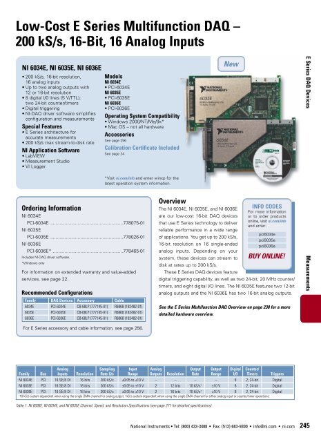
Low-Cost E <strong>Series</strong> <strong>Multifunction</strong> <strong>DAQ</strong> –<br />
200 kS/s, 16-Bit, 16 Analog Inputs<br />
NI 6034E, NI 6035E, NI 6036E<br />
• 200 kS/s, 16-bit resolution,<br />
16 analog inputs<br />
• Up to two analog outputs with<br />
12 or 16-bit resolution<br />
• 8 digital I/0 lines (5 V/TTL);<br />
two 24-bit counter/timers<br />
• Digital triggering<br />
• NI-<strong>DAQ</strong> driver software simplifies<br />
configuration and measurements<br />
Special Features<br />
• E <strong>Series</strong> architecture for<br />
accurate measurements<br />
• 200 kS/s max stream-to-disk rate<br />
NI Application Software<br />
• LabVIEW<br />
• Measurement Studio<br />
• VI Logger<br />
Models<br />
NI 6034E<br />
• PCI-6034E<br />
NI 6035E<br />
• PCI-6035E<br />
NI 6036E<br />
• PCI-6036E<br />
Operating System Compatibility<br />
• Windows 2000/NT/Me/9x*<br />
• Mac OS – not all hardware<br />
Accessories<br />
See page 256<br />
Calibration Certificate Included<br />
See page 24<br />
*Visit ni.com/info and enter winxp for the<br />
latest operation system information.<br />
Ordering Information<br />
NI 6034E<br />
PCI-6034E ........................................................778075-01<br />
NI 6035E<br />
PCI-6035E ........................................................778026-01<br />
NI 6036E<br />
PCI-6036E* ......................................................778465-01<br />
Includes NI-<strong>DAQ</strong> driver software.<br />
*Windows only<br />
For information on extended warranty and value-added<br />
services, see page 22.<br />
Recommended Configurations<br />
Family <strong>DAQ</strong> Devices Accessory Cable<br />
6034E PCI-6034E CB-68LP (777145-01) R6868 (182482-01)<br />
6035E PCI-6035E CB-68LP (777145-01) R6868 (182482-01)<br />
6036E PCI-6036E CB-68LP (777145-01) R6868 (182482-01)<br />
For E <strong>Series</strong> accessory and cable information, see page 256.<br />
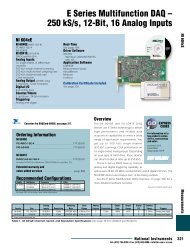
Overview<br />
The NI 6034E, NI 6035E, and NI 6036E<br />
are our low-cost 16-bit <strong>DAQ</strong> devices<br />
that use E <strong>Series</strong> technology to deliver<br />
reliable performance in a wide range<br />
of applications. You get up to 200 kS/s,<br />
16-bit resolution on 16 single-ended<br />
analog inputs. Depending on your<br />
system, these devices can stream to<br />
disk at rates up to 200 kS/s.<br />
These E <strong>Series</strong> <strong>DAQ</strong> devices feature<br />
INFO CODES<br />
For more information<br />
or to order products<br />
online, visit ni.com/info<br />
and enter:<br />
pci6034e<br />
pci6035e<br />
pci6036e<br />
BUY ONLINE!<br />
digital triggering capability, as well as two 24-bit, 20 MHz counter/<br />
timers, and eight digital I/O lines. The NI 6035E features two 12-bit<br />
analog outputs and the NI 6036E has two 16-bit analog outputs.<br />
See the E <strong>Series</strong> <strong>Multifunction</strong> <strong>DAQ</strong> Overview on page 230 for a more<br />
detailed hardware overview.<br />
Analog Sampling Input Analog Output Output Digital Counter/<br />
Family Bus Inputs Resolution Rate S/s Range Outputs Resolution Rate Range I/O Timers Triggers<br />
NI 6034E PCI 16 SE/8 DI 16 bits 200 kS/s ±0.05 to ±10 V – – – – 8 2, 24-bit Digital<br />
NI 6035E PCI 16 SE/8 DI 16 bits 200 kS/s ±0.05 to ±10 V 2 12 bits 10 kS/s 1 ±10 V 8 2, 24-bit Digital<br />
NI 6036E PCI 16 SE/8 DI 16 bits 200 kS/s ±0.05 to ±10 V 2 16 bits 10 kS/s 1 ±10 V 8 2, 24-bit Digital<br />
1 10 kS/s system dependent when using the single DMA channel for analog output. 1kS/s system dependent when using the single DMA channel for either analog input or counter/timer operations.<br />
Table 1. NI 6036E, NI 6034E, and NI 6035E Channel, Speed, and Resolution <strong>Specifications</strong> (see page 271 for detailed specifications)<br />
New<br />
National Instruments • Tel: (800) 433-3488 • Fax: (512) 683-9300 • info@ni.com • ni.com<br />
E <strong>Series</strong> <strong>DAQ</strong> Devices Measurements<br />
245
E <strong>Series</strong> <strong>DAQ</strong> Devices<br />
Measurements<br />
Low-Cost E <strong>Series</strong> <strong>Multifunction</strong> <strong>DAQ</strong> –<br />
200 kS/s, 16-Bit, 16 Analog Inputs<br />
Absolute Accuracy Relative Accuracy<br />
Nominal Range (V) % of Reading Offset Noise + Quantization (µV) Temp Absolute Accuracy Resolution (µV)<br />
Positive FS Negative FS 24 Hrs 1 Year (µV) Single Pt. Averaged Drift (%/°C) at Full Scale (mV) Single Pt. Averaged<br />
10.0 -10.0 0.0646 0.0688 1591.4 885.0 77.90 0.0010 8.553 1025.20 102.50<br />
5.0 -5.0 0.0146 0.0188 806.2 442.5 38.90 0.0005 1.787 512.60 51.26<br />
0.5 -0.5 0.0646 0.0688 99.5 53.4 4.76 0.0010 0.448 62.73 6.27<br />
0.05 -0.05 0.0646 0.0688 28.9 26.4 2.57 0.0010 0.066 33.80 3.38<br />
Note: Accuracies are valid for measurements following an internal E <strong>Series</strong> Calibration. Averaged numbers assume dithering and averaging of 100 single-channel readings. Measurement accuracies are listed for<br />
operational temperatures within ±1 °C of internal calibration temperature and ±10 °C of external or factory-calibration temperature. One-year calibration interval recommended. The Absolute Accuracy at Full Scale<br />
calculations were performed for a maximum range input voltage (for example, 10 V for the ±10 V range) after one year, assuming 100 pt averaging of data. See overview on page 234 for an example calculations.<br />
Table 2. NI 6034E, NI 6035E, and NI 6036E Analog Input Accuracy <strong>Specifications</strong><br />
Absolute Accuracy Absolute<br />
Nominal % of Reading Temp Accuracy at<br />
Family Range (V) FS 24 Hrs 90 Days 1 Year Offset (mV) Drift (%/°C) Full Scale (mV)<br />
NI 6035E ±10 0.18 0.02 0.022 5.93 0.0005 8.127<br />
NI 6036E ±10 0.009 0.011 0.013 1.1 0.0005 2.417<br />
Note: Temp Drift applies only if ambient is greater than ±10 °C of previous external calibration. See page 234 for example calculations.<br />
Table 3. NI 6034E, NI 6035E, and NI 6036E Analog Output Accuracy <strong>Specifications</strong><br />
Figure 1. NI 6034E, NI 6035E, and NI 6036E Block Diagram<br />
See page 233 in the E <strong>Series</strong> <strong>Multifunction</strong> <strong>DAQ</strong><br />
Overview for I/O connector diagrams.<br />
See page 271 for more detailed specifications.<br />
246 National Instruments • Tel: (800) 433-3488 • Fax: (512) 683-9300 • info@ni.com • ni.com<br />
PCI
E <strong>Series</strong> <strong>DAQ</strong> Accessories<br />
Measurements<br />
E <strong>Series</strong> <strong>Multifunction</strong> <strong>DAQ</strong> Accessories<br />
Selection Guide<br />
Step 1. Select your E <strong>Series</strong> device.<br />
Step 2. Using Tables 1 and 2 as a guide, determine which accessories<br />
are appropriate for that device. Select an accessory. Table 3 provides<br />
descriptions for E <strong>Series</strong> device accessories.<br />
Step 3. Using Tables 1 and 2, determine which cable is required to<br />
connect your selected device and accessory.<br />
Accessory<br />
Device<br />
TBX-68, CB-68LP, CB-68LPR, <strong>DAQ</strong> Signal Accessory,<br />
CA-1000, BNC-2110, BNC-2120, BNC-2090, SCB-68 TB-2705<br />
Cables<br />
SCXI, Signal Conditioning SCC Modular<br />
68-pin E <strong>Series</strong> SH68-68-EP (shielded) Connects directly to See page 385 for See page 461 for SCC Modular<br />
(except <strong>DAQ</strong>Card) R6868 (unshielded) the device (PXI only) SCXI Signal Conditioning details Signal Conditioning details<br />
Latching <strong>DAQ</strong>Cards SHC68-68-EP (shielded) N/A See page 385 for See page 461 for SCC Modular<br />
NI 6024E, NI 6062E RC68-68 (unshielded) SCXI Signal Conditioning details Signal Conditioning details<br />
Nonlatching <strong>DAQ</strong>Cards PSHR68-68 (shielded) N/A See page 385 for See page 461 for SCC Modular<br />
AI-16E-4, AI-16XE-50 PR68-68F (unshielded) SCXI Signal Conditioning details Signal Conditioning details<br />
Table 1. Accessories and Cables for 68-Pin and <strong>DAQ</strong>Card E <strong>Series</strong> Devices<br />
Accessory<br />
TBX-68, CB-68LP, CB-68LPR,<br />
<strong>DAQ</strong> Signal Accessory, CA-1000, TBX-68, CB-68LP SCC Modular<br />
BNC-2110, BNC-2120, CB-68LPR, CA-1000, SCXI Signal Signal<br />
Device BNC-2090, SCB-68 BNC-2115 SCB-68<br />
Cables<br />
SCB-100 Conditioning Conditioning<br />
100-pin E <strong>Series</strong> with SH1006868 (shielded); splits into two SH1006868 (shielded); splits SH1006868 (shielded); splits SH100100 See page 385 for See page 461 for<br />
64 AI channels 68-pin connectors; these accessories splits into two 68-pin into two 68-pin connectors; (shielded) SCXI Signal SCC Modular Signal<br />
NI 6071E, NI 6031E, are used with the first 68-pin connector. connectors;these accessories these accessories are used Conditioning details Conditioning details<br />
NI 6033E AT-MIO-64E-3 See Figure 16 on page 260. are used with the second with the second 68-pin<br />
68-pin connector. connector.<br />
100-pin E <strong>Series</strong> with SH1006868 (shielded); splits ino two SH1006868 (shielded); splits SH1006868 (shielded); splits SH100100 See page 385 for See page 461 for<br />
16 AI channels 68-pin connectors; these accessories splits into two 68-pin into two 68-pin connectors; (shielded) SCXI Signal SCC Modular Signal<br />
and 32 DIO lines are used with the first 68-pin connector. connectors;these accessories these accessories are used Conditioning details Conditioning details<br />
PCI-6025E, See Figure 16 on page 260. are used with the second with the second 68-pin<br />
AT-6021E 68-pin connector. connector.<br />
Table 2. Accessories and Cables for 100-Pin and <strong>DAQ</strong>Card E <strong>Series</strong> Devices<br />
Accessory Description Page<br />
SCXI Signal Conditioning High channel-count signal conditioning platform 385<br />
SCC Modular Signal Conditioning Single or dual channel signal conditioning modules 461<br />
AMUX-64T, 5B, SSR, ER, and SC-204x Signal Conditioning External signal conditioning accessories 478<br />
BNC-2110 BNC accessory for 68-pin E <strong>Series</strong> devices 257<br />
BNC-2115 BNC accessory for extended I/O on 100-pin E <strong>Series</strong> devices 257<br />
BNC-2120 BNC accessory with function generator (for 68-pin E <strong>Series</strong> devices) 257<br />
BNC-2090 Rack-mountable BNC accessory (for 68-pin E <strong>Series</strong> devices) 257<br />
CA-1000 enclosure Configurable connectivity enclosure 257<br />
TB-2705 Latching screw terminal block for PXI E <strong>Series</strong> modules 258<br />
SCB-100 100-pin, shielded screw terminal block with breadboard areas 258<br />
SCB-68 68-pin, shielded screw terminal block with breadboard areas 258<br />
TBX-68 68-pin, DIN rail-mountable screw terminal block 258<br />
CB-68LP, CB-68LPR 68-pin, low-cost screw terminal block 258<br />
Signal Source and Demo Accessory <strong>DAQ</strong> signal accessory to demo and test analog, digital and counter/timer functions 259<br />
For complete and up-to-date information about accessories, visit ni.com/catalog<br />
Table 3. Overview of E <strong>Series</strong> <strong>DAQ</strong> Accessories<br />
256 National Instruments • Tel: (800) 433-3488 • Fax: (512) 683-9300 • info@ni.com • ni.com
E <strong>Series</strong> <strong>Multifunction</strong> <strong>DAQ</strong> Accessories<br />
SCXI High-Performance Signal Conditioning (see Figure 1)<br />
SCXI is a modular high-performance signal conditioning platform that you use as a<br />
front end to your E <strong>Series</strong> <strong>DAQ</strong> device. With the SCXI multiplexing architecture, you<br />
can expand your analog inputs to 3,072 channels. Additionally, SCXI offers a variety of<br />
modules for connecting to thermocouples, RTDs, strain gauge transducers, LVDT<br />
position sensors, ICP-compatible accelerometers/microphones, thermistors, millivolt<br />
inputs, voltage inputs up to 1000 V, current inputs (0-20mA), frequency inputs or<br />
dynamic signals.<br />
See page 385 for details on SCXI Signal Conditioning.<br />
SCC <strong>Series</strong> – Modular Signal Conditioning<br />
for Low-Channel Count Applications (see Figure 2)<br />
The SCC <strong>Series</strong> modular signal conditioning system consists of SCC modules that<br />
plug into a low-profile SC-2345 shielded carrier. SCC modules give you single or<br />
dual-channel signal conditioning for up to 16 analog input channels and eight<br />
digital I/O lines of your plug-in E <strong>Series</strong> <strong>DAQ</strong> device. The SCC <strong>Series</strong> offers signal<br />
conditioning for a variety of inputs, including thermocouples, RTDs, strain gauges,<br />
ICP-compatible accelerometers, accelerators, analog inputs requiring isolation,<br />
high voltage (up to 100 V), current (0-20mA), and optically isolated digital I/O.<br />
Lowpass filtering and bread boarding modules are also available.<br />
See page 461 for details on SCC Signal Conditioning.<br />
Connector Blocks<br />
BNC-2100 <strong>Series</strong> Connector Blocks (see Figure 3)<br />
Shielded connector blocks with signal-labeled BNC connectors for easy connectivity of<br />
your analog input, analog output, digital I/O and counter/timer signals to your E <strong>Series</strong><br />
device. The BNC-2110 and BNC-2120 work with all E <strong>Series</strong> devices. The BNC-2120<br />
also provides a function generator, quadrature encoder, temperature reference,<br />
thermocouple connector and LED so that you can test the functionality of your hardware.<br />
The BNC-2115 has 24 BNC inputs for connecting to the extended I/O channels of our<br />
100-pin E <strong>Series</strong> <strong>DAQ</strong> devices.<br />
BNC-2110................................................................................................777643-01<br />
Dimensions – 20.3 by 11.2 by 5.5 cm (8.0 by 4.4 by 2.2 in.)<br />
BNC-2115................................................................................................777807-01<br />
Dimensions – 20.3 by 11.2 by 5.5 cm (8.0 by 4.4 by 2.2 in.)<br />
BNC-2120................................................................................................777960-01<br />
Dimensions – 26.7 by 11.2 by 6.0 cm (10.5 by 4.4 by 2.4 in.)<br />
BNC-2090 Shielded BNC Adapter Chassis (see Figure 4)<br />
Shielded, rack-mountable adapter with signal-labeled BNC connectors, spring<br />
terminal blocks, and component locations for passive signal conditioning. Consists of<br />
22 BNC connectors and 28 spring terminals to simplify connection to your analog,<br />
digital, trigger and counter/timer signals. The BNC-2090 has silk-screened<br />
component locations that you use to develop simple signal conditioning circuits. For<br />
added flexibility, you can connect any E <strong>Series</strong> <strong>DAQ</strong> device to the BNC-2090 from<br />
the front or rear through dual 68-pin connectors.<br />
BNC-2090 ...............................................................................................777270-01<br />
Dimensions – 48.3 by 4.4 by 18.8 cm (19.0 by 1.7 by 7.4 in.)<br />
Figure 1. SCXI High-Performance Signal Conditioning<br />
Figure 2. SCC Portable, Modular Signal Conditioning<br />
Figure 3. BNC-2100 <strong>Series</strong> Connector Blocks<br />
Figure 4. BNC-2090 Shielded BNC Adapter Chassis<br />
Figure 5. CA-1000 Configurable Signal Conditioning Enclosure<br />
National Instruments • Tel: (800) 433-3488 • Fax: (512) 683-9300 • info@ni.com • ni.com<br />
E <strong>Series</strong> <strong>DAQ</strong> Accessories Measurements<br />
257
E <strong>Series</strong> <strong>DAQ</strong> Accessories<br />
Measurements<br />
E <strong>Series</strong> <strong>Multifunction</strong> <strong>DAQ</strong> Accessories<br />
Figure 6. TB-2705 Terminal Block<br />
Figure 7. SCB-68 and SCB-100 Shielded I/O Connector Blocks<br />
Figure 8. TBX-68 I/O Connector Block<br />
Figure 9. CB-68LP and CB-68LPR I/O Connector Blocks<br />
Figure 10. <strong>DAQ</strong> Signal Accessory<br />
258 National Instruments • Tel: (800) 433-3488 • Fax: (512) 683-9300 • info@ni.com • ni.com<br />
CA-1000 Configurable Signal Conditioning Enclosure (see Figure 5)<br />
Configurable enclosure that gives you maximum user-defined connectivity and<br />
flexibility through customized panelettes. Each enclosure can accommodate up to<br />
9 panelettes.<br />
Dimensions – 30.7 by 25.4 by 4.3 cm (21.1 by 10 by 1.7 in.)<br />
See page 263 for more information about the CA-1000.<br />
TB-2705 Terminal Block for 68-pin PXI E <strong>Series</strong> Devices (see Figure 6)<br />
Screw terminal block for PXI that works with your PXI E <strong>Series</strong> <strong>DAQ</strong> devices.<br />
Latches to the front of your PXI module with locking screws and provides strain<br />
relief as well as easy access to your analog, digital, trigger and counter/timer<br />
signals through screw terminals.<br />
TB-2705 ................................................................................................778241-01<br />
Dimensions – 8.43 by 10.41 by 2.03 cm (3.32 by 4.1 by 0.8 in.)<br />
SCB-68 and SCB-100 Shielded I/O Connector Blocks (see Figure 7)<br />
Shielded I/O connector blocks for rugged, very low-noise signal termination for<br />
connecting to 68-pin or 100-pin E <strong>Series</strong> <strong>DAQ</strong> devices, respectively. Silk-screened<br />
component locations for easy addition of simple signal-conditioning circuitry for<br />
your analog input channels. They also include general-purpose breadboard areas<br />
(two on the SCB-68; three on the SCB-100) as well as an IC temperature sensor<br />
for cold-junction compensation in temperature measurements.<br />
SCB-68 ..................................................................................................776844-01<br />
Dimensions – 19.5 by 15.2 by 4.5 cm (7.7 by 6.0 by 1.8 in.)<br />
SCB-100 ................................................................................................776990-01<br />
Dimensions – 19.5 by 15.2 by 4.5 cm (7.7 by 6.0 by 1.8 in.)<br />
TBX-68 I/O Connector Block with DIN-Rail Mounting (see Figure 8)<br />
Termination accessory with 68 screw terminals for easy connection of field I/O<br />
signals to 68-pin <strong>DAQ</strong> devices. Includes one 68-pin male connector for direct<br />
connection to 68-pin cables. The TBX-68 is mounted in a protective plastic base<br />
with hardware for mounting on a standard DIN rail.<br />
TBX-68 ..................................................................................................777141-01<br />
Dimensions – 12.50 by 10.74 cm (4.92 by 4.23 in.)<br />
CB-68LP and CB-68LPR I/O Connector Blocks (see Figure 9)<br />
Low-cost termination accessory with 68 screw terminals for easy connection of<br />
field I/O signals to 68-pin E <strong>Series</strong> <strong>DAQ</strong> devices. Includes one 68-pin male<br />
connector for direct connection to 68-pin cables. The connector blocks include<br />
standoffs for use on a desktop or for mounting in a custom panel. The CB-68LP<br />
has a vertical-mounted 68-pin connector. The CB-68LPR has a right-angle mounted<br />
connector, and is used with the CA-1000 (see page 263).<br />
CB-68LP ................................................................................................777145-01<br />
Dimensions – 14.35 by 10.74 cm (5.65 by 4.23 in.)<br />
CB-68LPR ............................................................................................777145-02<br />
Dimensions – 7.62 by 16.19 cm (3.00 by 6.36 in.)
Signal Source and Demo Accessory (see Figure 10)<br />
The <strong>DAQ</strong> Signal Accessory demonstrates and tests the use of analog, digital, and<br />
counter/timer functions of <strong>DAQ</strong> devices. You can connect the <strong>DAQ</strong> Signal<br />
Accessory directly to your <strong>DAQ</strong> device. It features a built-in function generator,<br />
quadrature encoder, solid-state relay, IC temperature sensor, noise generator,<br />
microphone jack, thermocouple jack, four LEDs, and a digital trigger button. The<br />
<strong>DAQ</strong> Signal Accessory works with all E <strong>Series</strong> <strong>DAQ</strong> devices.<br />
<strong>DAQ</strong> Signal Accessory............................................................................777382-01<br />
Dimensions – 12.7 by 12.7 cm (5.0 by 5.0 in.)<br />
RTSI Bus Cables (see Figures 11 and 12)<br />
Use RTSI bus cables to connect timing and synchronization signals among<br />
Measurement, Vision, Motion, and Controller Area Network (CAN) boards for PCI<br />
and ISA and <strong>DAQ</strong>Pad 6070E boards. For systems using long and short boards order<br />
the extended RTSI cable.<br />
2 boards ..................................................................................................776249-02<br />
3 boards .................................................................................................776249-03<br />
4 boards .................................................................................................776249-04<br />
5 boards ..................................................................................................776249-05<br />
Extended, 5 boards ................................................................................777562-05<br />
3 external boards ....................................................................................186464-01<br />
Shielded I/O Cables<br />
SH68-68-EP Shielded Cable (see Figure 13)<br />
Shielded 68-conductor cable terminated with two 68-pin female 0.050 series<br />
D-type connectors. Features individually-shielded analog twisted pairs for reduced<br />
crosstalk with high-speed devices. This cable works with all 68-pin E <strong>Series</strong><br />
devices (except latching <strong>DAQ</strong>Cards). If you need a right-angle connector, the<br />
SH68-68R1-EP shielded cable is fully compatible.<br />
1 m..........................................................................................................184749-01<br />
2 m..........................................................................................................184749-02<br />
SH68-68R1-EP Shielded Cable (see Figure 14)<br />
Shielded 68-conductor cable; one end terminates with a 68-pin female 0.050<br />
series D-type connector and the other end terminates with a right-angle 68-pin<br />
female 0.050 series D-type connector.<br />
1 m..........................................................................................................187051-01<br />
SH100100 Shielded Cable (see Figure 15)<br />
Shielded 100-conductor cable terminated with 100-pin male 0.050 series D-type<br />
connectors. This cable connects the 100-pin E <strong>Series</strong> devices to 100-pin accessories.<br />
1 m..........................................................................................................182853-01<br />
2 m..........................................................................................................182853-02<br />
E <strong>Series</strong> <strong>Multifunction</strong> <strong>DAQ</strong><br />
Accessories and Cables<br />
Figure 11. RTSI Bus Cable<br />
Figure 12. Extended RTSI Bus Cable<br />
Figure 13. SH68-68-EP Shielded Cable<br />
Figure 14. SH68-68R1-EP Shielded Cable<br />
Figure 15. SH100100 Shielded Cable<br />
National Instruments • Tel: (800) 433-3488 • Fax: (512) 683-9300 • info@ni.com • ni.com<br />
E <strong>Series</strong> <strong>DAQ</strong> Accessories and Cables Measurements<br />
259
E <strong>Series</strong> <strong>DAQ</strong> Accessories and Cables<br />
Measurements<br />
E <strong>Series</strong> <strong>Multifunction</strong> <strong>DAQ</strong><br />
Accessories and Cables<br />
Figure 16. SH1006868 Shielded Cable<br />
Figure 17. SHC68-68-EP Shielded Cable<br />
Figure 18. PSHR68-68 Shielded Cable Kit<br />
Figure 19. PSHR68-68M Shielded Cable<br />
Figure 20. R6868 Ribbon Cable<br />
260 National Instruments • Tel: (800) 433-3488 • Fax: (512) 683-9300 • info@ni.com • ni.com<br />
SH1006868 Shielded Cable (see Figure 16)<br />
Shielded cable that connects to 100-pin E <strong>Series</strong> devices and terminates with two<br />
female 68-pin 0.050 series D-type connectors. See Table 2 on page 256 for accessories<br />
compatible with each 68-pin connector.<br />
1 m ........................................................................................................182849-01<br />
2 m ........................................................................................................182849-02<br />
SHC68-68-EP and SHC68U-68-EP Shielded Cables<br />
for Latching E <strong>Series</strong> <strong>DAQ</strong>Cards (see Figure 17)<br />
These cables connect a latching E <strong>Series</strong> <strong>DAQ</strong>Card (NI 6062E and NI 6024E) to<br />
standard 68-pin accessories. Latching screws secure the shielded connector to<br />
the PCMCIA <strong>DAQ</strong>Card. The SHC68-68-EP is a shielded 68-conductor cable<br />
terminated with a VHDCI 68-pin male connector at one end and a 68-pin female<br />
0.050 series D-type connector at the other. The SHC68U-68-EP is identical to the<br />
SHC68-68-EP except it uses an inverted VHDCI 68-pin male connector. Use the<br />
SH68U-68-EP for a <strong>DAQ</strong>Card located in the bottom PCMCIA slot in your laptop.<br />
Use the SHC68-68-EP cable with a <strong>DAQ</strong>Card inserted in the upper PCMCIA slot<br />
in your laptop. When using two E <strong>Series</strong> <strong>DAQ</strong>Card PCMCIA devices in adjacent<br />
slots, you must use one SHC68-68-EP and one SHC68U-68-EP.<br />
SHC68-68-EP<br />
0.5 m ..................................................................................................186838-0R5<br />
1 m ........................................................................................................186838-01<br />
SHC68U-68-EP<br />
0.5 m ..................................................................................................187406-0R5<br />
1 m ........................................................................................................187406-01<br />
PSHR68-68 Shielded Cable Kit for Nonlatching <strong>DAQ</strong>Cards (see Figure 18)<br />
Shielded cable for use in connecting non-latching E <strong>Series</strong> <strong>DAQ</strong>Cards (AI-16E-4<br />
and AI-16XE-50) with 68-pin accessories. The kit contains the PSHR68-68M, the<br />
PCMCIA Strain-Relief Adapter and a 1 m SH68-68-EP cable.<br />
1 m ........................................................................................................777293-01<br />
PSHR68-68M Shielded Cable for Nonlatching <strong>DAQ</strong>Cards (see Figure 19)<br />
Shielded cable for use in connecting non-latching E <strong>Series</strong> <strong>DAQ</strong>Cards (AI-16E-4<br />
and AI-16XE-50) with custom cables and other 68-pin cable assemblies.<br />
0.1 m ....................................................................................................183569-01
Ribbon I/O Cables<br />
R6868 Ribbon Cable for E <strong>Series</strong> Devices (see Figure 20)<br />
68-conductor flat ribbon cable terminated with two 68-pin connectors. Use this<br />
cable to connect a 68-pin E <strong>Series</strong> device to 68-pin accessories.<br />
1 m ........................................................................................................182482-01<br />
RC68-68 Ribbon Cable for Latching <strong>DAQ</strong>Cards (see Figure 21)<br />
Ribbon cable that connects to a latching E <strong>Series</strong> <strong>DAQ</strong>Card (NI 6062E, NI 6024E)<br />
and is terminated with a 68-pin female connector that attaches directly to 68-pin<br />
accessories. Two RC68-68 cables can be used together in adjacent PCMCIA slots.<br />
0.25 m ..............................................................................................187252-0R25<br />
1 m ........................................................................................................187252-01<br />
PR68-68F for Non-Latching <strong>DAQ</strong>Cards (see Figure 22)<br />
Ribbon cable that connects to a non-latching E <strong>Series</strong> <strong>DAQ</strong>Card (AI-16E-4,<br />
AI-16XE-50) and is terminated with a 68-pin female connector that attaches<br />
directly to 68-pin accessories.<br />
0.2 m ..................................................................................................183646-0R2<br />
1 m ........................................................................................................183646-01<br />
Custom Connectivity Components<br />
68-Pin Custom Cable Connector/Backshell Kit (see Figure 23)<br />
68-pin female mating connector and backshell kit for use in making custom cables.<br />
Solder-cup contacts are available for soldering of cable wires to the connector.<br />
68-pin connector/backshell kit ................................................................776832-01<br />
PCB Mounting Connectors for Custom Accessories (see Figure 24)<br />
PCB connectors for use in building custom accessories that connect to<br />
68-conductor or 100-conductor shielded and ribbon cables. Two connectors are<br />
available, one for right-angle and one for vertical mounting onto a PCB.<br />
68-position, male, right-angle mounting ................................................777600-01<br />
68-position, male, vertical mounting ......................................................777601-01<br />
100-position, female, right-angle mounting ............................................777778-01<br />
100-position, female, vertical mounting..................................................777779-01<br />
PCMCIA Strain-Relief Accessory (see Figure 25)<br />
Accessory that attaches to the bottom of your notebook computer and provides<br />
adjustable strain relief for one or two PCMCIA cables attached to the installed<br />
PCMCIA card(s). Used with non-latching E <strong>Series</strong> <strong>DAQ</strong>Cards (AI-16E-4, AI-16XE-50).<br />
PCMCIA Strain-Relief Accessory ............................................................777550-01<br />
E <strong>Series</strong> <strong>Multifunction</strong> <strong>DAQ</strong><br />
Accessories and Cables<br />
Figure 21. RC68-68 Ribbon Cable<br />
Figure 22. PR68-68F Ribbon Cable<br />
Figure 23. 68-Pin Custom Cable Connector/Backshell Kit<br />
Figure 24. PCB Mounting Connectors for Custom Accessories<br />
Figure 25. PCMCIA Strain-Relief Accessory<br />
National Instruments • Tel: (800) 433-3488 • Fax: (512) 683-9300 • info@ni.com • ni.com<br />
E <strong>Series</strong> <strong>DAQ</strong> Accessories and Cables Measurements<br />
261
E <strong>Series</strong> <strong>DAQ</strong> Accessories and Cables<br />
Measurements<br />
E <strong>Series</strong> <strong>Multifunction</strong> <strong>DAQ</strong><br />
Accessories and Cables<br />
Figure 26. USB Cable<br />
Figure 27. IEEE 1394 Cable<br />
Use Interactive Online Catalog Configurator for<br />
Quick Product Selection<br />
You can now easily configure NI multifunction data acquisition (<strong>DAQ</strong>)<br />
measurement systems using a new, interactive feature<br />
of our online catalog. The interactive online catalog offers a better,<br />
easier way to select and purchase measurement solutions<br />
from National Instruments. Based on user imput, the interactive online<br />
catalog suggests products and then suggests the appropriate cables<br />
and accessories for those products. This new automated tool helps<br />
eliminate ordering mistakes and product-compatibility errors.<br />
To take advantage of the online catalog for multifunction <strong>DAQ</strong><br />
devices, visit ni.com/catalog<br />
From the Products and Services menu, select Data Acquisition,<br />
then select <strong>Multifunction</strong> I/O. The online catalog prompts you with a<br />
series of questions regarding preferences for operating system,<br />
computer bus, number of channels, and maximum sampling rate.<br />
The online catalog then recommends several appropriate <strong>DAQ</strong><br />
devices. You can review specifications on each device and select<br />
your preferred product. Next, the catalog suggests the preferred<br />
accessory and cable solution designed to work with the selected<br />
<strong>DAQ</strong> device. You have the option of choosing the preferred<br />
configuration or choosing from a separate list of accessories and<br />
cables that also work with the selected <strong>DAQ</strong> device. You can<br />
purchase the selected items online.<br />
262 National Instruments • Tel: (800) 433-3488 • Fax: (512) 683-9300 • info@ni.com • ni.com<br />
USB Cable (see Figure 26)<br />
Cable that connects <strong>DAQ</strong>Pad devices for the Universal Serial Bus (USB) to a USB port.<br />
The USB cables have a USB B-type connector and a USB A-type connector.<br />
1 m ........................................................................................................184125-01<br />
2 m ........................................................................................................184125-02<br />
IEEE 1394 Cable (see Figure 27)<br />
Cable that connects <strong>DAQ</strong>Pad devices for IEEE 1394 (FireWire) to an IEEE 1394 port.<br />
1 m (latching)..........................................................................................185798-01<br />
2 m (latching)..........................................................................................185798-02<br />
Figure 28. Use the interactive configuration tool in the NI online catalog to select and<br />
purchase multifunction <strong>DAQ</strong> solutions.
CA-1000<br />
Configurable Signal Conditioning Enclosure<br />
• Versatile connector/enclosure<br />
system<br />
• Houses signal conditioning and<br />
connector block accessories<br />
• Wide variety of I/O connectivity<br />
and panelette options<br />
• Holds maximum of 18<br />
connectivity/interface panelettes<br />
• Low profile enclosure<br />
• Rack-mount and stacking kits<br />
available<br />
I/O Connectivity<br />
• BNC<br />
• Thermocouple<br />
• Banana jack<br />
• LEMO ® connector (B-<strong>Series</strong>)<br />
• MIL-Spec<br />
• SMB<br />
• Dual 9-pin D-Sub<br />
• Strain relief<br />
Interface Panelettes<br />
• Momentary pushbutton switch<br />
• Potentiometer<br />
• Toggle switch<br />
• Rocker switch<br />
• LED<br />
Overview<br />
The National Instruments CA-1000 is a configurable signal conditioning<br />
enclosure designed for maximum user-defined I/O connectivity and<br />
flexibility. The CA-1000 is a portable enclosure for laptop, desktop,<br />
and rack-mount applications. In the CA-1000, you can install many<br />
NI signal conditioning accessories, such as the SC-204x signal<br />
conditioning products, and the SCB-68, CB-68LPR, and CB-50LP<br />
terminal blocks. The result is a compact, portable, flexible, and<br />
comprehensive signal conditioning/interconnection system. The<br />
CA-1000 also facilitates quick connection and disconnection with<br />
standard I/O connectors for easy system integration and<br />
reconfiguration. By adding interface panelettes, such as toggle<br />
switches, potentiometers, and LEDs, you can locally control and<br />
verify system operation.<br />
Description<br />
The CA-1000 system includes four components: 1) CA-1000<br />
enclosure, 2) I/O and interface panelettes, 3) signal conditioning or<br />
measurement accessories installed in the CA-1000, and 4) for<br />
50-pin accessories, an internal cable adapter to connect the signal<br />
conditioning accessory to the cable attached to the CA-1000.<br />
CA-1000 Enclosure<br />
The metal enclosure provides a low-profile, portable housing for<br />
signal conditioning and connector accessories. You can place the<br />
enclosure under a laptop PC, on a benchtop, or in a 19 in. rack.<br />
You can also stack two or more enclosures with the stacking kit.<br />
The CA-1000 enclosure includes five cable entry locations, so you<br />
can place the 68-pin or 50-pin connector that you cable to your<br />
measurement device on either the side or the rear of the CA-1000<br />
enclosure. Please note, the CA-1000<br />
is shipped without any panelettes, signal INFO CODES<br />
For more information<br />
conditioning accessories, connector or to order products<br />
online, visit ni.com/info<br />
blocks, or cables. Order all of these<br />
and enter:<br />
components separately.<br />
ca1000<br />
Internal Accessories<br />
BUY ONLINE!<br />
The CA-1000 houses a variety of signal<br />
conditioning and data acquisition<br />
accessories, including the SC-204x,<br />
SCB-68, CB-68LPR, and CB-50LP (Table 1 on page 264). You mount<br />
these accessories to the bottom panel of the CA-1000 enclosure.<br />
I/O Panelettes<br />
The CA-1000 includes a user-configurable signal connection scheme.<br />
This connectivity flexibility is achieved with interchangeable<br />
panelettes. The panelettes, which come with standard signal<br />
connectors – for example, BNC, SMB, banana jack, thermocouple<br />
plugs, and LEMO, MIL-Spec, and 9-pin D-Sub connectors – mount<br />
in the front of the CA-1000 enclosure. The CA-1000 front panel<br />
offers nine panelette slots. The rear panel can also be removed<br />
offering nine more panelette slots. However, this option is not<br />
available if you are using the SCB-68 inside the CA-1000. You can<br />
mix and match different types of panelettes. Each panelette (except<br />
for the strain-relief panel) includes lead wires that you connect to<br />
the screw terminals of the accessory mounted inside the CA-1000.<br />
You can therefore connect the panelettes to any I/O signal available<br />
on the accessory.<br />
National Instruments • Tel: (800) 433-3488 • Fax: (512) 683-9300 • info@ni.com • ni.com<br />
Custom Conditioning Enclosure Measurements<br />
263
Custom Conditioning Enclosure<br />
Measurements<br />
Configurable Signal Conditioning Enclosure<br />
Interface Panelettes<br />
National Instruments also offers interface panelettes, which expand<br />
the functionality of the CA-1000. Interface panelettes include traditional<br />
interface controls and displays, such as rocker switches, toggle<br />
switches, momentary switches, potentiometers, and LEDs. Using<br />
interface panelettes, which are mounted alongside I/O panelettes, you<br />
can change hardware inputs, trigger events, or verify operational status.<br />
Each interface panelette includes lead wires for connection to the<br />
screw terminals of the accessory mounted inside the CA-1000.<br />
Cabling<br />
The cabling needed to connect the CA-1000 to the measurement<br />
device depends on the accessories installed in the CA-1000 and the<br />
Table 1. CA-1000 Cabling<br />
264 National Instruments • Tel: (800) 433-3488 • Fax: (512) 683-9300 • info@ni.com • ni.com<br />
measurement device used. Some accessories installed in the CA-1000<br />
require internal cabling to connect the accessory to the CA-1000 wall.<br />
Use Table 1 to determine what cabling components you need,<br />
including the cable to your measurement device.<br />
The CA-1000 also provides the flexibility of five external<br />
interconnection locations, giving convenient cabling for laptop<br />
applications by aligning the I/O connector with the location of the<br />
PCMCIA slots on laptop computers. With the five external<br />
interconnection locations, you can also customize desktop and<br />
rack-mount applications for added convenience.<br />
Device SC-204x <strong>Series</strong><br />
Connector Blocks<br />
CB-50LP CB-68LPR or SCB-68<br />
68-pin E <strong>Series</strong> <strong>DAQ</strong> Devices (except <strong>DAQ</strong>Cards) R68M-50F and SH68-68-EP1 N/A SH68-68-EP1 100-pin E <strong>Series</strong> <strong>DAQ</strong> Devices3 Applicable for one leg N/A SH1006868<br />
Latching E <strong>Series</strong> <strong>DAQ</strong>Cards: R68M-50F and SHC68-68-EP N/A SHC68-68-EP<br />
<strong>DAQ</strong>Card-6062E, <strong>DAQ</strong>Card-6024E – – –<br />
Nonlatching E <strong>Series</strong> <strong>DAQ</strong>Cards: R68M-50F and PSHR68-68 Shielded Cable Kit2 N/A PSHR68-68 Shielded Cable Kit2 <strong>DAQ</strong>Card-AI-16E-4, <strong>DAQ</strong>Card-AI-16XE-50<br />
68-pin Digital I/O and Counter/Timer Devices (except <strong>DAQ</strong>Cards) N/A N/A SH68-68-D1<br />
PCI-DIO-32HS, PXI-6533, AT-DIO-32HS, – – –<br />
NI 6534, NI 660x – – –<br />
Nonlatching 68-pin Digital I/O <strong>DAQ</strong>Cards: N/A N/A PSHR68-68-D1 Shielded Cable Kit<br />
<strong>DAQ</strong>Card-6533 – – –<br />
Simultaneous Sampling <strong>Multifunction</strong> <strong>DAQ</strong> Devices N/A N/A SH68-68-EP1 PCI-6503 N/A R5OM-50F and SH50-50 N/A<br />
PC-DIO-24 – – –<br />
<strong>DAQ</strong>Card-DIO-24 N/A R5OM-50F and PSH27-50F-D1 N/A<br />
NI 65273 , PCI-DIO-963 , PXI-65083 , <strong>DAQ</strong>Pad-65083 N/A Two R50M-50F and R1005050 4 N/A<br />
PC-DIO-963 N/A Two R50M-50F and NB5 4 N/A<br />
1 2 3<br />
You can also use the SH68-68R1-EP or R6868. You can also use the PR68-68F. You can use two CA-1000 enclosures with one of these devices. Please note: If you are using a NI 435x series data logger, please<br />
see Figure 1 on page 298 for information on cabling to a CB-68T and CA-1000. 4 Splits into two 50-pin connectors. See page 319 for information on using the CA-1000 with signal source products.<br />
Minithermocouple BNC SMB Dual 9-Pin D-Sub Banana Jack LEMO (B-<strong>Series</strong>) MIL-Spec<br />
Toggle Switch Rocker Switch LED Strain Relief Potentiometer Momentary Switch Blank Filler<br />
Table 2. CA-1000 Panelette Options
Configurable Signal Conditioning Enclosure<br />
Connectors/Units<br />
Panelette Description per Panelette Slot Width<br />
Minithermocouple Jack J-type 2 1<br />
K-type 2 1<br />
Uncompensated 2 1<br />
Thermocouple Jack J-type 1 1<br />
K-type 1 1<br />
Uncompensated 1 1<br />
BNC BNC connector 2 1<br />
SMB SMB connector 4 1<br />
Banana Jack Banana Jack 2 1<br />
LEMO 2-pin female 2 1<br />
4, 6-pin female 1 1<br />
MIL-Spec 2, 4, 6-pin female 1 1<br />
9-pin D-sub Single (male) 1 2<br />
Single (female) 1 2<br />
Dual (male) 2 3<br />
Dual (female) 2 3<br />
Momentary Pushbutton Switch On – off 2 1<br />
Toggle Switch (On – off – on) 2 1<br />
Rocker Switch (On – off – on) 1 1<br />
LED A red, green, yellow, 4 1<br />
and orange LED<br />
Potentiometer 1 turn, 10 kW 1 1<br />
Strain Relief Screw clamp 1 2<br />
Blank Filler panel – 1<br />
Table 3. CA-1000 Panelette descriptions<br />
Ordering Information<br />
CA-1000 (enclosure only) ....................................777664-01<br />
Dimensions – 30.7 by 25.4 by 4.3 cm (21.1 by 10.3 by 1.7 in.)<br />
I/O Connector Panelettes<br />
Minithermocouple, J-type (2 included) ................184736-01<br />
Minithermocouple, K-type (2 included) ................184736-02<br />
Minithermocouple, uncompensated (2 included) ......184736-03<br />
Thermocouple, J-type ..........................................187597-01<br />
Thermocouple, K-type ..........................................187597-02<br />
Thermocouple, uncompensated ..........................187597-03<br />
BNC (2 included) ..................................................184737-01<br />
Banana jack (2 included) ......................................186405-01<br />
LEMO connector (B-<strong>Series</strong>)<br />
Dual 2-pin, female ............................................187585-01<br />
4-pin, female ....................................................187585-02<br />
6-pin, female ....................................................187585-03<br />
MIL-C-26482 (<strong>Series</strong> 1)<br />
MS3112E8-2 S..................................................187591-01<br />
MS3112E8-4 S..................................................187591-02<br />
MS3112E10-6 S................................................187591-03<br />
SMB (4 included) ..................................................185505-01<br />
Ordering Information (continued)<br />
Strain relief............................................................184721-01<br />
9-Pin D-Sub<br />
Single male........................................................184738-01<br />
Dual male..........................................................184738-02<br />
Single female....................................................184738-03<br />
Dual female......................................................184738-04<br />
Blank ....................................................................184483-01<br />
Interface Panelettes<br />
Momentary pushbutton switch (2 included) ........185380-01<br />
Rocker switch (on/off/on)....................................185379-01<br />
Toggle switch (on/off/on – 2 included) ................185378-01<br />
Potentiometer (10 kΩ, single turn) ....................185377-01<br />
LED 4 – (Includes: 1 green,<br />
1 red, 1 orange, 1 yellow) ................................185376-01<br />
External Cables<br />
SH68-68-EP, 1 m ..................................................182419-01<br />
SH68-68-D1, 1 m..................................................183432-01<br />
SH68-68R1-EP, 1 m ..............................................187051-01<br />
SH50-50, 1 m ......................................................777720-01<br />
R6868, 1 m ..........................................................182482-01<br />
R1005050, 1 m ....................................................182762-01<br />
NB5, 1 m ..............................................................181304-10<br />
SH1006868, 1 m ..................................................182849-01<br />
PSHR68-68 Shielded Cable Kit ............................777293-01<br />
PSHR68-68-D1 Shielded Cable Kit ......................777420-01<br />
PR68-68F, 1 m ......................................................183646-01<br />
PSH27-50F-D1, 1 m..............................................776989-01<br />
SHC68-68-EP, 1 m ................................................186838-01<br />
Internal Cables<br />
R50M-50F ribbon cable......................................184526-0R3<br />
R68M-50F MIO bulkhead ribbon cable ..............777660-0R3<br />
Accessories<br />
CA-1000 Rack-Mount Kit (1U) ..............................777665-01<br />
CA-1000 Stacking Kit............................................777666-01<br />
CA-1000 Panel Mount Kit ....................................187243-01<br />
Strain Relief Kit 1 ....................................................187407-01<br />
1<br />
You cannot use the Strain Relief Kit in conjunction with<br />
the rack-mount, panel-mount, or stacking kits.<br />
For information on extended warranty and value added<br />
services, see page 22.<br />
National Instruments • Tel: (800) 433-3488 • Fax: (512) 683-9300 • info@ni.com • ni.com<br />
Custom Conditioning Enclosure Measurements<br />
265
E <strong>Series</strong> <strong>Multifunction</strong> <strong>DAQ</strong> Overview<br />
Self-Calibration Using an Internal Reference<br />
The E <strong>Series</strong> analog inputs and outputs have calibration circuitry to<br />
correct gain and offset errors. You can calibrate the device in<br />
software to avoid analog I/O errors caused by time and temperature<br />
drift at run time. No external circuitry is necessary; an internal<br />
reference ensures high accuracy and stability over time and<br />
temperature. Factory-calibration constants are permanently stored<br />
in an onboard EEPROM and cannot be modified. A modifiable<br />
section of the EEPROM stores user-modifiable constants. You can<br />
return the devices to their initial factory calibration by accessing the<br />
unmodified factory constants. Included with all E <strong>Series</strong> devices is<br />
an NIST-traceable and ISO-9002 certified calibration certificate. Visit<br />
ni.com/calibration for more information.<br />
I/O Interface – MITE and <strong>DAQ</strong>-PnP<br />
All of the PCI and PXI E <strong>Series</strong> use the MITE ASIC as a bus master<br />
interface to the PCI bus. The E <strong>Series</strong> products for ISA use an ASIC<br />
that fully implements the Plug and Play ISA Specification, so that the<br />
DMA level, interrupt channels, and base I/O address are all software<br />
configurable. All other E <strong>Series</strong> devices are inherently Plug and Play<br />
compatible. Visit ni.com/info and enter exniev to download<br />
a technical paper on bus mastering.<br />
RTSI Bus Interface<br />
All E <strong>Series</strong> devices except <strong>DAQ</strong>Cards, USB <strong>DAQ</strong>Pads, and PXI<br />
modules are interfaced to the National Instruments RTSI bus with<br />
an embedded cross-matrix switch in the <strong>DAQ</strong>-STC. This switch<br />
synchronizes several <strong>DAQ</strong> devices by sending timing signals to<br />
them on the RTSI bus. Using RTSI bus, a single master device can<br />
control one or more slave devices for both single and multiple A/D<br />
conversions. The PXI Trigger bus serves the same purpose for PXI<br />
systems as RTSI bus.<br />
E <strong>Series</strong> <strong>Multifunction</strong> <strong>DAQ</strong> Software<br />
NI-<strong>DAQ</strong><br />
NI-<strong>DAQ</strong>, our driver software bundled with every E <strong>Series</strong> multifunction<br />
<strong>DAQ</strong> device, provides access to the features of your <strong>DAQ</strong> hardware,<br />
so that you can easily develop powerful measurement solutions.<br />
You can use NI-<strong>DAQ</strong> to perform single-point and buffered<br />
analog I/O, digital I/O, and counter/timer input operations. You can<br />
perform those operations individually, or program your device to<br />
perform multiple operations simultaneously. To facilitate integration<br />
of signal conditioning in your system, NI-<strong>DAQ</strong> provides you with a<br />
single interface for programming both the E <strong>Series</strong> device and signal<br />
conditioning modules. Using NI-<strong>DAQ</strong>, you can also synchronize your<br />
E <strong>Series</strong> multifunction <strong>DAQ</strong> device with other measurement devices,<br />
to build measurement systems customized to your particular needs.<br />
Measurement & Automation Explorer<br />
NI Measurement & Automation Explorer (MAX) software, which is<br />
bundled with every E <strong>Series</strong> multifunction <strong>DAQ</strong> device, guides you<br />
through hardware configuration, channel scaling, and sensor set-up.<br />
You can also test the basic operation of your E <strong>Series</strong> device and<br />
signal connections using a test panel.<br />
What About Signal Conditioning?<br />
Signal conditioning is one of the most<br />
important, and most overlooked,<br />
components of a data acquisition system.<br />
Many sensors require special signal<br />
conditioning technology, and no <strong>DAQ</strong><br />
device has the capability to provide all<br />
types of signal conditioning to all<br />
sensors. Using NI signal conditioning<br />
products, you can measure a wide variety<br />
of signals and sensors. These modular<br />
conditioning devices come in a range of<br />
sizes, from rack-mountable SCXI systems<br />
to portable SCC systems.<br />
See page 383 for more information<br />
on Signal Conditioning,<br />
ACH8<br />
ACH1<br />
AIGND<br />
ACH10<br />
ACH3<br />
AIGND<br />
ACH4<br />
AIGND<br />
ACH13<br />
ACH6<br />
AIGND<br />
ACH15<br />
DAC1OUT 1<br />
DAC0OUT 1<br />
EXTREF 1<br />
DIO4<br />
DGND<br />
DIO1<br />
DIO6<br />
DGND<br />
+5 V<br />
DGND<br />
DGND<br />
PFI0/TRIG1<br />
PFI1/TRIG2<br />
DGND<br />
+5 V<br />
DGND<br />
PFI5/UPDATE*<br />
PFI6/WFTRIG<br />
DGND<br />
PFI9/GPCTR0_GATE<br />
GPCTR0_OUT<br />
FREQ_OUT<br />
34 68<br />
33 67<br />
32 66<br />
31 65<br />
30 64<br />
29 63<br />
28 62<br />
27 61<br />
26 60<br />
25 59<br />
24 58<br />
23 57<br />
22 56<br />
21 55<br />
20 54<br />
19 53<br />
18 52<br />
17 51<br />
16 50<br />
15 49<br />
14 48<br />
13 47<br />
12 46<br />
11 45<br />
10 44<br />
9 43<br />
8 42<br />
7 41<br />
6 40<br />
5 39<br />
4 38<br />
3 37<br />
2 36<br />
1 35<br />
ACH0<br />
AIGND<br />
ACH9<br />
ACH2<br />
AIGND<br />
ACH11<br />
AISENSE<br />
ACH12<br />
ACH5<br />
AIGND<br />
ACH14<br />
ACH7<br />
AOGND 1<br />
AIGND<br />
AOGND 1<br />
DGND<br />
DIO0<br />
DIO5<br />
DGND<br />
DIO2<br />
DIO7<br />
DIO3<br />
SCANCLK<br />
EXTSTROBE*<br />
DGND<br />
PFI2/CONVERT*<br />
PFI3/GPCTR1_SOURCE<br />
PFI4/GPCTR1_GATE<br />
GPCTR1_OUT<br />
DGND<br />
PFI7/STARTSCAN<br />
PFI8/GPCTR0_SOURCE<br />
DGND<br />
DGND<br />
1 Not available on AT-AI-16XE-10, PCI-6032E,<br />
<strong>DAQ</strong>Card-A1-16E-4, <strong>DAQ</strong>Card-A1-16XE-50<br />
Figure 3. 68-Pin I/O Connector for NI 6070E,<br />
NI 6060E, NI 6062E, NI 6052E, NI 6041E,<br />
NI 6040E, NI 6036E, NI 6035E, NI 6034E,<br />
NI 6032E, NI 6030E, NI 6024E, NI 6023E,<br />
NI 6020E, NI 6012E and NI 6011E Devices<br />
AIGND<br />
AIGND<br />
ACH0<br />
ACH8<br />
ACH1<br />
ACH9<br />
ACH2<br />
ACH10<br />
ACH3<br />
ACH11<br />
ACH4<br />
ACH12<br />
ACH5<br />
ACH13<br />
ACH6<br />
ACH14<br />
ACH7<br />
ACH15<br />
AISENSE<br />
DAC0OUT 1<br />
DAC1OUT 1<br />
EXTREF 1<br />
AOGND 1<br />
DGND<br />
DIO0<br />
DIO4<br />
DIO1<br />
DIO5<br />
DIO2<br />
DIO6<br />
DIO3<br />
DIO7<br />
DGND<br />
+5 V<br />
+5 V<br />
SCANCLK<br />
EXTSTROBE*<br />
PFI0/TRIG1<br />
PFI1/TRIG2<br />
PFI2/CONVERT*<br />
PFI3/GPCTR1_SOURCE<br />
PFI4/GPCTR1_GATE<br />
GPCTR1_OUT<br />
PFI5/UPDATE*<br />
PFI6/WFTRIG<br />
PFI7/STARTSCAN<br />
PFI8/GPCTR0_SOURCE<br />
PFI9/GPCTR0_GATE<br />
GPCTR0_OUT<br />
FREQ_OUT<br />
AIGND<br />
AIGND<br />
ACH0<br />
ACH8<br />
ACH1<br />
ACH9<br />
ACH2<br />
ACH10<br />
ACH3<br />
ACH11<br />
ACH4<br />
ACH12<br />
ACH5<br />
ACH13<br />
ACH6<br />
ACH14<br />
ACH7<br />
ACH15<br />
AISENSE<br />
DAC0OUT<br />
DAC1OUT<br />
RESERVED<br />
AOGND<br />
DGND<br />
DIO0<br />
DIO4<br />
DIO1<br />
DIO5<br />
DIO2<br />
DIO6<br />
DIO3<br />
DIO7<br />
DGND<br />
+5 V<br />
+5 V<br />
SCANCLK<br />
EXTSTROBE*<br />
PFI0/TRIG1<br />
PFI1/TRIG2<br />
PFI2/CONVERT*<br />
PFI3/GPCTR1_SOURCE<br />
PFI4/GPCTR1_GATE<br />
GPCTR1_OUT<br />
PFI5/UPDATE*<br />
PFI6/WFTRIG<br />
PFI7/STARTSCAN<br />
GPCTR0_SOURCE<br />
GPCTR0_GATE<br />
GPCTR0_OUT<br />
FREQ_OUT<br />
1<br />
2<br />
3<br />
4<br />
5<br />
6<br />
7<br />
8<br />
9<br />
10<br />
11<br />
12<br />
13<br />
14<br />
15<br />
16<br />
17<br />
18<br />
19<br />
20<br />
21<br />
22<br />
23<br />
24<br />
25<br />
26<br />
27<br />
28<br />
29<br />
30<br />
31<br />
32<br />
33<br />
34<br />
35<br />
36<br />
37<br />
38<br />
39<br />
40<br />
41<br />
42<br />
43<br />
44<br />
45<br />
46<br />
47<br />
48<br />
49<br />
50<br />
51<br />
52<br />
53<br />
54<br />
55<br />
56<br />
57<br />
58<br />
59<br />
60<br />
61<br />
62<br />
63<br />
64<br />
65<br />
66<br />
67<br />
68<br />
69<br />
70<br />
71<br />
72<br />
73<br />
74<br />
75<br />
76<br />
77<br />
78<br />
79<br />
80<br />
81<br />
82<br />
83<br />
84<br />
85<br />
86<br />
87<br />
88<br />
89<br />
90<br />
91<br />
92<br />
93<br />
94<br />
95<br />
96<br />
97<br />
98<br />
99<br />
100<br />
1 Not available on PCI-6033E<br />
ACH16<br />
ACH24<br />
ACH17<br />
ACH25<br />
ACH18<br />
ACH26<br />
ACH19<br />
ACH27<br />
ACH20<br />
ACH28<br />
ACH21<br />
ACH29<br />
ACH22<br />
ACH30<br />
ACH23<br />
ACH31<br />
ACH32<br />
ACH40<br />
ACH33<br />
ACH41<br />
ACH34<br />
ACH42<br />
ACH35<br />
ACH43<br />
AISENSE2<br />
AIGND<br />
ACH36<br />
ACH44<br />
ACH37<br />
ACH45<br />
ACH38<br />
ACH46<br />
ACH39<br />
ACH47<br />
ACH48<br />
ACH56<br />
ACH49<br />
ACH57<br />
ACH50<br />
ACH58<br />
ACH51<br />
ACH59<br />
ACH52<br />
ACH60<br />
ACH53<br />
ACH61<br />
ACH54<br />
ACH62<br />
ACH55<br />
ACH63<br />
Figure 2. 100-Pin I/O Connector for NI 6071E,<br />
NI 6061E, NI 6031E, NI 6033E Devices<br />
National Instruments • Tel: (800) 433-3488 • Fax: (512) 683-9300 • info@ni.com • ni.com<br />
1<br />
2<br />
3<br />
4<br />
5<br />
6<br />
7<br />
8<br />
9<br />
10<br />
11<br />
12<br />
13<br />
14<br />
15<br />
16<br />
17<br />
18<br />
19<br />
20<br />
21<br />
22<br />
23<br />
24<br />
25<br />
26<br />
27<br />
28<br />
29<br />
30<br />
31<br />
32<br />
33<br />
34<br />
35<br />
36<br />
37<br />
38<br />
39<br />
40<br />
41<br />
42<br />
43<br />
44<br />
45<br />
46<br />
47<br />
48<br />
49<br />
50<br />
51<br />
52<br />
53<br />
54<br />
55<br />
56<br />
57<br />
58<br />
59<br />
60<br />
61<br />
62<br />
63<br />
64<br />
65<br />
66<br />
67<br />
68<br />
69<br />
70<br />
71<br />
72<br />
73<br />
74<br />
75<br />
76<br />
77<br />
78<br />
79<br />
80<br />
81<br />
82<br />
83<br />
84<br />
85<br />
86<br />
87<br />
88<br />
89<br />
90<br />
91<br />
92<br />
93<br />
94<br />
95<br />
96<br />
97<br />
98<br />
99<br />
100<br />
PC7<br />
GND<br />
PC6<br />
GND<br />
PC5<br />
GND<br />
PC4<br />
GND<br />
PC3<br />
GND<br />
PC2<br />
GND<br />
PC1<br />
GND<br />
PC0<br />
GND<br />
PB7<br />
GND<br />
PB6<br />
GND<br />
PB5<br />
GND<br />
PB4<br />
GND<br />
PB3<br />
GND<br />
PB2<br />
GND<br />
PB1<br />
GND<br />
PB0<br />
GND<br />
PA7<br />
GND<br />
PA6<br />
GND<br />
PA5<br />
GND<br />
PA4<br />
GND<br />
PA3<br />
GND<br />
PA2<br />
GND<br />
PA1<br />
GND<br />
PA0<br />
GND<br />
+5 V<br />
GND<br />
Figure 4. 100-Pin I/O Connector for<br />
NI 6021E and NI 6025E Devices<br />
E <strong>Series</strong> <strong>DAQ</strong> Overview Measurements<br />
233
E <strong>Series</strong> <strong>Multifunction</strong> <strong>DAQ</strong> <strong>Specifications</strong><br />
<strong>Specifications</strong> – 16-Bit E <strong>Series</strong> NI 6052E, NI 603xE, and NI 601xE<br />
These specifications are typical for 25 °C unless otherwise noted.<br />
Analog Input<br />
Accuracy specifications ............................. See tables in E <strong>Series</strong> product pages<br />
Input Characteristics<br />
Number of channels<br />
6052E 16 single-ended or 8 differential<br />
6030E (software selectable per channel)<br />
6032E<br />
6034E<br />
6035E<br />
6036E<br />
601xE<br />
6031E 64 single-ended or 32 differential<br />
6033E (software selectable per channel)<br />
Type of ADC............................................... Successive approximation<br />
Resolution .................................................. 16 bits, 1 in 65,536<br />
Maximum sampling rate<br />
6052E 333 kS/s<br />
6034E 200 kS/s<br />
6035E<br />
6036E<br />
6030E 100 kS/s<br />
6031E<br />
6032E<br />
6033E<br />
601xE 20 kS/s;<br />
200 kS/s single-channel sampling with<br />
the <strong>DAQ</strong>Card-AI-16XE-50 Streaming-to-disk rate (system dependent) 1<br />
6052E 333 kS/s<br />
6034E 200 kS/s<br />
6035E<br />
6036E<br />
6030E 100 kS/s<br />
6031E<br />
6032E<br />
6033E<br />
601xE 20 kS/s<br />
1Streaming-to-disk rates do not apply to RT <strong>Series</strong> devices<br />
Input signal ranges<br />
Range Bipolar Unipolar<br />
Device Software Selectable Input Range Input Range<br />
6052E 20 V ±10 V –<br />
10 V ±5 V 0 to 10 V<br />
5 V ±2.5 V 0 to 5 V<br />
2 V ±1 V 0 to 2 V<br />
1 V ±500 mV 0 to 1 V<br />
500 mV ±250 mV 0 to 500 mV<br />
200 mV ±100 mV 0 to 200 mV<br />
100 mV ±50 mV 0 to 100 mV<br />
6030E 20 V ±10 V –<br />
6031E 10 V ±5 V 0 to 10 V<br />
6032E 5 V – 0 to 5 V<br />
6033E 4 V ±2 V –<br />
2 V ±1 V 0 to 2 V<br />
1 V ±500 mV 0 to 1 V<br />
500 mV – 0 to 500 mV<br />
400 mV ±200 mV –<br />
200 mV ±100 mV 0 to 200 mV<br />
100 mV – 0 to 100 mV<br />
6034E 20 V ±10 V –<br />
6035E 10 V ±5 V –<br />
6036E 1 V ±500 mV –<br />
100 mV ±50 mV –<br />
601xE 20 V ±10 V –<br />
10 V ±5 V 0 to 10 V<br />
5 V – 0 to 5 V<br />
2 V ±1 V –<br />
1 V – 0 to 1 V<br />
200 mV ±100 mV –<br />
100 mV – 0 to 100 mV<br />
Input coupling ............................................ DC<br />
Maximum working voltage<br />
(signal + common mode) .................... Each input should remain within<br />
±11 V of ground<br />
Overvoltage protection<br />
Powered on .......................................... ±25 V<br />
Powered off.......................................... ±15 V<br />
Inputs protected<br />
6052E ACH, AISENSE<br />
6030E<br />
6032E<br />
6034E<br />
6035E<br />
6036E<br />
601xE<br />
6031E ACH, AISENSE,<br />
6033E AISENSE2<br />
FIFO buffer size ........................................ 512 samples, (1024 samples for<br />
<strong>DAQ</strong>Card; 2048 for PCI-MIO-16XE-50)<br />
Data transfers<br />
PCI, PXI, AT .......................................... DMA, interrupts, programmed I/O<br />
<strong>DAQ</strong>Card .............................................. Interrupts, programmed I/O<br />
DMA modes<br />
PCI, PXI ................................................ Scatter-gather (single transfer,<br />
demand transfer)<br />
AT ......................................................... Single transfer, demand transfer<br />
Configuration memory size........................ 512 words<br />
National Instruments • Tel: (800) 433-3488 • Fax: (512) 683-9300 • info@ni.com • ni.com<br />
Measurements<br />
271<br />
16-Bit E <strong>Series</strong> <strong>Specifications</strong>
16-Bit E <strong>Series</strong> <strong>Specifications</strong><br />
Measurements<br />
E <strong>Series</strong> <strong>Multifunction</strong> <strong>DAQ</strong> <strong>Specifications</strong><br />
16-Bit E <strong>Series</strong> NI 6052E, NI 603xE, and NI 601xE (continued)<br />
Transfer Characteristics<br />
Relative accuracy (dithered)<br />
Device Typical Maximum<br />
6052E<br />
6034E<br />
6035E<br />
6036E<br />
±1.5 LSB ±3 LSB<br />
6030E<br />
6031E<br />
6032E<br />
6033E<br />
±0.75 LSB ±1 LSB<br />
6011E ±0.5 LSB ±1 LSB<br />
6012E ±1.5 LSB ±2 LSB<br />
DNL<br />
Device Typical Maximum<br />
6052E<br />
603xE<br />
6011E<br />
±0.5 LSB ±1 LSB<br />
6012E +1.5 to -0.75 LSB +2.25 to -1.0 LSB<br />
No missing codes ...................................... 16 bits, guaranteed<br />
Amplifier Characteristics<br />
Input impedance<br />
Device Normal Powered On Powered Off Overload<br />
6052E 100 GΩ in parallel 820 Ω 820 Ω<br />
603xE with 100 pF<br />
601xE 7 GΩ in parallel with 100 pF 820 Ω; 820 Ω;<br />
1 kΩ for 1 kΩ for<br />
<strong>DAQ</strong>Card <strong>DAQ</strong>Card<br />
Input bias and offset current<br />
Device Bias Current Offset Current<br />
6052E<br />
6034E<br />
6035E<br />
6036E<br />
±200 pA ±100 pA<br />
6030E<br />
6031E<br />
6032E<br />
6033E<br />
±1 nA ±2 nA<br />
6011E ±10 nA ±20 nA<br />
6012E ±10 nA ±14 nA<br />
CMRR, DC to 60 Hz<br />
CMRR<br />
Device Range Bipolar Unipolar<br />
6052E 20 V 92 dB –<br />
10 V 97 dB 97 dB<br />
5 V 101 dB 101 dB<br />
2 V 104 dB 104 dB<br />
100 mV to 1 V 105 dB 105 dB<br />
6030E 20 V 92 dB –<br />
6031E 10 V 97 dB 92 dB<br />
6032E 5 V – 97 dB<br />
6033E 4 V 101 dB –<br />
2 V 104 dB 101 dB<br />
1 V 105 dB 104 dB<br />
100 mV to 500 mV 105 dB 105 dB<br />
6034E 20 V 85 dB –<br />
6035E 10 V 85 dB –<br />
6036E 1 V 96 dB –<br />
100 mV 96 dB –<br />
601xE 20 V 80 dB –<br />
10 V 86 dB 80 dB<br />
5 V – 86 dB<br />
2 V 100 dB –<br />
1 V – 100 dB<br />
200 mV 120 dB –<br />
100 mV – 120 dB<br />
272 National Instruments • Tel: (800) 433-3488 • Fax: (512) 683-9300 • info@ni.com • ni.com<br />
Dynamic Characteristics<br />
Bandwidth<br />
Device Range Small Signal (-3 dB)<br />
6052E All ranges 480 kHz<br />
6030E All ranges 255 kHz<br />
6031E<br />
6032E<br />
6033E<br />
6034E All ranges 413 kHz<br />
6035E<br />
6036E<br />
6011E 5 to 20 V 63 kHz<br />
1 to 2 V 57 kHz<br />
100 to 200 mV 33 kHz<br />
6012E 5 to 20 V 69 kHz<br />
1 to 2 V 66 kHz<br />
100 to 200 mV 39 kHz<br />
System noise (LSBrms, including quantization)<br />
Device Range Bipolar Unipolar<br />
6052E 2 to 20 V 0.95 0.95<br />
1 V 1.1 1.1<br />
500 mV 1.3 1.3<br />
200 mV 2.3 2.3<br />
100 mV 4.2 4.2<br />
6030E 2 to 20 V 0.6 0.8<br />
6031E 1 V 0.7 0.8<br />
6032E 400 to 500 mV 1.1 1.1<br />
6033E 200 mV 2.0 2.0<br />
100 mV – 3.8<br />
6034E 10 to 20 V 0.8 –<br />
6035E 1 V 1.0 –<br />
6036E 100 mV 5.6 –<br />
6010E 1 to 20 V 0.5 0.5<br />
100 to 200 mV 0.8 1.4<br />
6011E 1 to 20 V 1.0 1.0<br />
100 to 200 mV 1.2 1.6<br />
Settling time to full-scale step<br />
±0.00076% ±0.0015%<br />
Accuracy<br />
±0.0031% ±0.0061% ±0.024%<br />
Device Range (±0.5 LSB) (±1 LSB) (±2 LSB) (±4 LSB) (±16 LSB)<br />
6052E 2 to 20 V 20 µs typical 10 µs max 5 µs max 4 µs max 3 µs typical<br />
1 V 20 µs typical 15 µs max 5 µs max 4 µs max 3 µs typical<br />
200 to 500 mV 20 µs typical 15 µs max 8 µs max 4 µs max 3 µs typical<br />
100 mV 20 µs typical 15 µs max 10 µs max 4 µs max 3 µs typical<br />
6030E<br />
6032E<br />
All 40 µs max 20 µs max – 10 µs max –<br />
6031E<br />
6033E<br />
All 50 µs max 25 µs max – 10 µs max –<br />
6034E 1 to 20 V – – 5 µs max – –<br />
6035E<br />
6036E<br />
100 mV – – – 5 µs typical –<br />
6011E 1 to 20 V – 50 µs max – 50 µs max –<br />
200 mV (bipolar), 75 µs max 50 µs max<br />
100 mV (unipolar) 75 µs max 50 µs max<br />
6012E 1 to 20 V – – 50 µs max 50 µs max –<br />
200 mV (bipolar), 60 µs max 50 µs typical<br />
100 mV (unipolar) 60 µs max 50 µs typical<br />
Crosstalk<br />
Device Adjacent Channels All Other Channels<br />
6052E<br />
603xE<br />
-75 dB -90 dB<br />
601xE -85 dB -100 dB
Analog Output<br />
Output Characteristics<br />
Number of channels<br />
E <strong>Series</strong> <strong>Multifunction</strong> <strong>DAQ</strong> <strong>Specifications</strong><br />
16-Bit E <strong>Series</strong> NI 6052E, NI 603xE, and NI 601xE (continued)<br />
6052E 2 voltage outputs<br />
6030E<br />
6031E<br />
6035E<br />
6036E<br />
6011E<br />
6032E None<br />
6033E<br />
6034E<br />
6012E<br />
Resolution<br />
6052E 16 bits, 1 in 65,536<br />
6036E<br />
6030E<br />
6031E<br />
6035E 12 bits, 1 in 4,096<br />
6011E<br />
Maximum update rate<br />
6052E 333 kS/s<br />
6035E 10 kS/s, system dependent<br />
6036E<br />
6030E 100 kS/s<br />
6031E<br />
6011E 20 kS/s, system dependent<br />
Type of DAC............................................... Double buffered, multiplying<br />
FIFO buffer size<br />
6052E 2,048 samples<br />
6030E<br />
6031E<br />
6035E None<br />
6036E<br />
6011E<br />
Data transfers<br />
PCI, PXI, AT .......................................... DMA, interrupts, programmed I/O<br />
<strong>DAQ</strong>Card .............................................. Interrupts, programmed I/O<br />
DMA modes<br />
PCI, PXI ................................................ Scatter-gather (single transfer,<br />
demand transfer)<br />
AT ......................................................... Single transfer, demand transfer<br />
Transfer Characteristics<br />
Relative accuracy<br />
6052E ±0.35 LSB typical, ±1 LSB max<br />
6030E ±0.5 LSB typical, ±1 LSB max<br />
6031E<br />
6035E ±0.3 LSB typical, ±0.5 LSB max<br />
6036E ±2 LSB max<br />
6011E ±0.5 LSB max<br />
DNL............................................................ ±1.0 LSB max<br />
Monotonicity<br />
6052E 16 bits, guaranteed<br />
6036E<br />
6030E<br />
6031E<br />
6035E 12 bits, guaranteed<br />
6011E<br />
Voltage Output<br />
Ranges<br />
6052E ±10 V, 0 to 10 V, ±EXTREF, 0 to EXTREF; software selectable<br />
6030E<br />
6031E<br />
±10 V, 0 to 10 V; software selectable<br />
6035E<br />
6036E<br />
6011E<br />
±10 V<br />
Output coupling ......................................... DC<br />
Output impedance ..................................... 0.1 Ω max<br />
Current drive .............................................. ±5 mA max<br />
Protection...................................................<br />
Power-on state<br />
Short-circuit to ground<br />
6052E<br />
6030E<br />
6031E<br />
0 V (±20 mV)<br />
6035E 0 V (±200 mV)<br />
6036E 0 V (±21 mV)<br />
6011E 0 V (±85 mV)<br />
External reference input (6052E only)<br />
Range ................................................... ±11 V<br />
Overvoltage protection......................... ±25 V powered on, ±15 V powered off<br />
Input impedance................................... 10 kΩ<br />
Bandwidth (-3 dB)................................. 3 kHz<br />
Slew rate ..............................................<br />
Dynamic Characteristics<br />
Settling time and slew rate<br />
0.3 V/µs<br />
Device Settling Time for Full-Scale Step Slew Rate<br />
6052E 3.5 µs to ±1 LSB accuracy 15 V/µs<br />
6030E<br />
6031E<br />
10 µs to ±1 LSB accuracy 5 V/µs<br />
6035E 10 µs to ±0.5 LSB accuracy 10 V/µs<br />
6036E 5 µs to ±1 LSB accuracy 15 V/µs<br />
6011E 50 µs to ±0.5 LSB accuracy 2 V/µs<br />
Noise<br />
6052E 60 µVrms, DC to 1 MHz<br />
6030E<br />
6031E<br />
6035E 200 µVrms, DC to 1 MHz<br />
6036E 110 µVrms, DC to 400 kHz<br />
6011E 40 µVrms, DC to 1 MHz<br />
Glitch energy (at mid-scale transition)<br />
Digital I/O<br />
Number of channels .................................. 8 input/output<br />
Compatibility .............................................. 5 V/TTL<br />
Device Magnitude Duration<br />
6052E ±10 mV 1 µs<br />
6030E<br />
6031E<br />
N/A N/A<br />
6035E ±12 mV 2 µs<br />
6036E ±10 mV 1 µs<br />
6011E ±30 mV 10 µs<br />
Power-on state........................................... Input (high impedance)<br />
Data transfers ............................................ Programmed I/O<br />
Digital logic levels<br />
Level Minimum Maximum<br />
Input low voltage 0 V 0.8 V<br />
Input high voltage 2 V 5 V<br />
Output low voltage (Iout = 24 mA) – 0.4 V<br />
Output high voltage (Iout = 13 mA) 4.35 V –<br />
National Instruments • Tel: (800) 433-3488 • Fax: (512) 683-9300 • info@ni.com • ni.com<br />
16-Bit E <strong>Series</strong> <strong>Specifications</strong> Measurements<br />
273
16-Bit E <strong>Series</strong> <strong>Specifications</strong><br />
Measurements<br />
E <strong>Series</strong> <strong>Multifunction</strong> <strong>DAQ</strong> <strong>Specifications</strong><br />
<strong>Specifications</strong> – 16-Bit E <strong>Series</strong> NI 6052E, NI 603xE, and NI 601xE (continued)<br />
Timing I/O<br />
General-Purpose Up/Down Counter/Timers<br />
Number of channels .................................. 2<br />
Resolution .................................................. 24 bits (1 in 16, 777, 216)<br />
Compatibility .............................................. 5 V/TTL<br />
Digital logic levels<br />
Level Minimum Max<br />
Input low voltage 0.0 V 0.8 V<br />
Input high voltage 2.0 V 5.0 V<br />
Output low voltage (Iout = 5 mA) – 0.4 V<br />
Output high voltage (Iout = 3.5 mA) 4.35 V –<br />
Base clocks available ................................. 20 MHz and 100 kHz<br />
Base clock accuracy................................... ±0.01%<br />
Maximum source frequency...................... 20 MHz<br />
External source selections......................... PFI0..PFI9, RTSI0..RTSI6, analog<br />
trigger; software selectable<br />
External gate selections............................. PFI0..PFI9, RTSI0..RTSI6, analog<br />
trigger; software selectable<br />
Minimum source pulse duration................ 10 ns<br />
Minimum gate pulse duration....................<br />
Data transfers<br />
10 ns, edge-detect mode<br />
PCI, PXI, AT .......................................... DMA, interrupts, programmed I/O<br />
<strong>DAQ</strong>Card ..............................................<br />
DMA modes<br />
Interrupts, programmed I/O<br />
PCI, PXI ................................................ Scatter-gather (single transfer, demand<br />
transfer)<br />
AT .........................................................<br />
Frequency Scaler<br />
Single transfer, demand transfer<br />
Number of channels .................................. 1<br />
Resolution .................................................. 4 bits<br />
Compatibility .............................................. 5 V/TTL<br />
Digital logic levels<br />
Level Minimum Max<br />
Input low voltage 0.0 V 0.8 V<br />
Input high voltage 2.0 V 5.0 V<br />
Output low voltage (Iout = 5 mA) – 0.4 V<br />
Output high voltage (Iout = 3.5 mA) 4.35 V –<br />
Base clocks available ................................. 10 MHz, 100 kHz<br />
Base clock accuracy................................... ±0.01%<br />
Data transfers ............................................ Programmed I/O<br />
Triggers<br />
Analog Triggers<br />
Number of triggers<br />
274 National Instruments • Tel: (800) 433-3488 • Fax: (512) 683-9300 • info@ni.com • ni.com<br />
6052E 1<br />
6030E<br />
6031E<br />
6032E<br />
6033E<br />
6034E None<br />
6035E<br />
6036E<br />
601xE<br />
Purpose<br />
Analog input ......................................... Start and stop trigger, gate, clock<br />
Analog output ....................................... Start trigger, gate, clock<br />
General-purpose counter/timers........... Source, gate<br />
Source<br />
6052E ACH, PF10/TRIG1<br />
6030E<br />
6032E<br />
6031E ACH, PF10/TRIG1<br />
6033E<br />
Level<br />
Internal source, ACH .......... ±Full-scale<br />
External source, PFI0/TRIG1 ................ ±10 V<br />
Slope .......................................................... Positive or negative; software selectable<br />
Resolution .................................................. 12 bits, 1 in 4,096<br />
Hysteresis ..................................................<br />
Bandwidth (-3 dB)<br />
Programmable<br />
Accuracy ................................................... ±1% of full-scale range max<br />
Internal source External Source<br />
Device ACH PFIO/TRIG1<br />
6052E 700 kHz 700 kHz<br />
6030E, 6031E, 6032E, 6033E 255 kHz 4 MHz<br />
Digital Triggers (all devices)<br />
Number of triggers .................................... 2<br />
Purpose<br />
Analog input ......................................... Start and stop trigger, gate, clock<br />
Analog output ....................................... Start trigger, gate, clock<br />
General-purpose counter/timers........... Source, gate<br />
Source........................................................ PFI0..PFI9, RTSI0..RTSI6<br />
Slope .......................................................... Positive or negative; software selectable<br />
Compatibility .............................................. 5 V/TTL<br />
Response ................................................... Rising or falling edge<br />
Pulse width ................................................ 10 ns minimum
E <strong>Series</strong> <strong>Multifunction</strong> <strong>DAQ</strong> <strong>Specifications</strong><br />
16-Bit E <strong>Series</strong> NI 6052E, NI 603xE, and NI 601xE (continued)<br />
External Input for Digital or Analog Trigger (PFI0/TRIG1)<br />
Impedance ................................................. 10 kΩ<br />
Coupling ..................................................... DC<br />
Protection<br />
Digital trigger ........................................ -0.5 to (Vcc + 0.5) V<br />
Analog trigger<br />
On/Off/Disabled .............................. ±35 V<br />
Calibration<br />
Recommended warm-up time................... 15 minutes; 30 minutes for <strong>DAQ</strong>Card<br />
Calibration Interval ..................................... 1 year<br />
Onboard calibration reference<br />
DC Level<br />
6052E 5.000 V (±1.0 mV) Over full operating temperature,<br />
6030E actual value stored in EEPROM<br />
6031E<br />
6032E<br />
6033E<br />
6012E<br />
6034E 5.000 V (±3.5 mV)<br />
6035E<br />
6036E<br />
6011E 5.000 V (±3.0 mV)<br />
Temperature coefficient<br />
6052E ±0.6 ppm/°C max<br />
6030E<br />
6031E<br />
6032E<br />
6033E<br />
6012E ±5.0 ppm/°C max<br />
6034E<br />
6035E<br />
6036E<br />
6011E ±2.0 ppm/°C max<br />
Long-term stability<br />
6052E ±6.0 ppm/ √1000 h<br />
6030E<br />
6031E<br />
6032E<br />
6033E<br />
6034E ±15.0 ppm/ √1000 h<br />
6035E<br />
6036E<br />
601xE<br />
RTSI (PCI and ISA only)<br />
Trigger lines................................................ 7<br />
PXI Trigger Bus (PXI only)<br />
Trigger lines................................................ 6<br />
Star Trigger................................................. 1<br />
Bus Interface<br />
PCI, PXI...................................................... Master, slave<br />
AT, <strong>DAQ</strong>Card.............................................. Slave<br />
Power Requirements 1<br />
Device +5 VDC (±5%) Power Available at I/O Connector<br />
6052E 1.3 A +4.65 to +5.25 VDC, 1 A<br />
603xE (PCI, PXI); except 1.5 A +4.65 to +5.25 VDC, 1 A<br />
6034E/6035E<br />
6034E 0.9 A +4.65 to +5.25 VDC, 1 A<br />
6035E<br />
6036E<br />
603xE (AT) 1.2 A +4.65 to +5.25 VDC, 1 A<br />
PCI-MIO-16XE-50 1.1 A +4.65 to +5.25 VDC, 1 A<br />
<strong>DAQ</strong>Card-A1-16XE-50 230 mA +4.65 to +5.25 VDC, 250 mA<br />
AT-MIO-16XE-50 750 mA +4.65 to +5.25 VDC, 1 A<br />
Physical1 Dimensions (not including connectors) 1<br />
PCI ........................................................ 17.5 by 10.6 cm (6.9 by 4.2 in.)<br />
PXI ........................................................ 16.0 by 10.0 cm (6.3 by 3.9 in.)<br />
ISA (long) .............................................. 33.8 by 9.9 cm (13.3 by 3.9 in.)<br />
ISA (short)............................................. 17.5 by 9.9 cm (6.9 by 4.2 in.)<br />
<strong>DAQ</strong>Card .............................................. Type II PC Card<br />
I/O connectors<br />
6052E 68-pin male SCSI-II type<br />
6030E<br />
6032E<br />
6034E<br />
6035E<br />
6036E<br />
6011E<br />
6031E 100-pin female 0.050 D-type<br />
6033E<br />
6012E 68-pin female PCMCIA<br />
Environment<br />
Operating temperature .............................. 0 to 55 °C; <strong>DAQ</strong>Cards should not<br />
exceed 55 °C while in PCMCIA slot<br />
Storage temperature.................................. -20 to 70 °C<br />
Relative humidity ....................................... 10 to 90%, noncondensing<br />
Certifications and Compliances<br />
CE Mark Compliance<br />
1 See page 148 for RT <strong>Series</strong> devices power requirements and physical parameters.<br />
National Instruments • Tel: (800) 433-3488 • Fax: (512) 683-9300 • info@ni.com • ni.com<br />
16-Bit E <strong>Series</strong> <strong>Specifications</strong> Measurements<br />
275
E <strong>Series</strong> <strong>DAQ</strong> Accuracy <strong>Specifications</strong><br />
Measurements<br />
E <strong>Series</strong> <strong>DAQ</strong> Accuracy <strong>Specifications</strong><br />
Every Measurement Counts<br />
There is no room for error in your measurements. From sensor to<br />
software, your system must deliver accurate results. NI provides<br />
detailed specifications for our products so that you do not have to<br />
guess how they will perform. Along with traditional data acquisition<br />
specifications, our E <strong>Series</strong> multifunction data acquisition (<strong>DAQ</strong>)<br />
devices also include accuracy tables to assist you in selecting the<br />
appropriate hardware for your application. These tables are found<br />
on the product pages and include specifications for both absolute<br />
and relative accuracy.<br />
Absolute Accuracy<br />
Absolute accuracy is the specification you use to determine<br />
the overall maximum error of your measurement. Absolute accuracy<br />
specifications apply only to a successfully calibrated <strong>DAQ</strong> device.<br />
There are four components of an absolute accuracy specification:<br />
Percent of Reading is a percent of the actual input voltage.<br />
Offset is a constant offset applied to all measurements.<br />
Noise + Quantization is based on noise and depends on the<br />
number of points averaged for each measurement.<br />
Drift is based on variations in your ambient temperature.<br />
Based on these components, the formula for calculating absolute<br />
accuracy is:<br />
Absolute Accuracy = ±[(Input Voltage X % of Reading) +<br />
(Offset + Noise + Quantization + Drift)]<br />
Drift is already accounted for unless your ambient temperature is<br />
outside +15 to +35 °C. For instance, if your ambient temperature<br />
is at 45 °C, you must account for 10 °C of drift. This is calculated by:<br />
Drift = Temperature Difference X % Drift per °C X Input Voltage<br />
Absolute Accuracy at Full Scale is a calculation of absolute accuracy<br />
for a specific voltage range using the maximum voltage within that<br />
range taken one year after calibration, the Accuracy Drift Reading,<br />
and the Noise + Quantization averaged value.<br />
234 National Instruments • Tel: (800) 433-3488 • Fax: (512) 683-9300 • info@ni.com • ni.com<br />
Below is the Absolute Accuracy at Full Scale calculation for the<br />
PCI-MIO-16XE-50 after one year using the ±10 V input range<br />
while averaging 100 samples of a 10 V input signal. In all the<br />
Absolute Accuracy at Full Scale calculations, we assume that the<br />
ambient temperature is between 15 and 35 °C. You can see on<br />
the next page that the calculation for the ±10 V input range for<br />
Absolute Accuracy at Full Scale yields 1.443 mV. This calculation<br />
is done using the parameters in the same row for one year<br />
Absolute Accuracy Reading, Offset and Noise + Quantization as<br />
well as a value of 10 V for the input voltage value. You can then<br />
see that the calculation is as follows:<br />
Absolute Accuracy = ±[(10 X 0.0001) + 397.2 µV + 45.8 µV] = ±1.443 mV<br />
The following example assumes the same conditions except that<br />
the ambient temperature is 45 °C. You can begin with the calculation<br />
above and add in the Drift calculation using the % Drift per °C from<br />
the table on the next page (see Table 1).<br />
Absolute Accuracy = 1.443mV + ((45 °C – 35 °C) X 0.000002 /°C X 10 V) = ±1.643 mV<br />
If you are making single-point measurements, use the Single-Point<br />
Noise + Quantization specification from the accuracy tables. If you<br />
are averaging multiple points for each measurement, the value for<br />
Noise + Quantization changes. The Averaged Noise + Quantization<br />
in the accuracy tables assumes that you average 100 points per<br />
measurement. If you are averaging a different number of points,<br />
use the following equation to determine your Noise + Quantization:<br />
Noise + Quantization for x averaged points =<br />
Averaged Noise + Quantization from table X √ _____<br />
100/X<br />
For example, if you are averaging 1000 points per measurement<br />
with the PCI-MIO-16XE-50 in the ±10 V input range, the Noise +<br />
Quantization is determined by:<br />
Noise + Quantization = 45.7 µV X √ ________ 100/1000 = 14.5 µV<br />
The Noise + Quantization specifications assume that dithering<br />
is disabled for single-point measurements and enabled for<br />
averaged measurements.<br />
See page 24 or visit ni.com/calibration for more information<br />
on the importance of calibration on <strong>DAQ</strong> device accuracy.<br />
To calculate the accuracy of NI measurement products,<br />
visit ni.com/measurements/accuracy
E <strong>Series</strong> <strong>DAQ</strong> Accuracy <strong>Specifications</strong><br />
Relative Accuracy<br />
Relative accuracy is the specification that compares the difference<br />
between two or more measurements. It indicates the degree to<br />
which two or more measurements can be distinguished from each<br />
other. The two major contributors to relative accuracy are the<br />
resolution of the device’s analog-to-digital Converter (ADC) and the<br />
system noise. The accuracy tables show both single-point and<br />
averaged relative accuracy, which include both ADC resolution and<br />
system noise effects. Averaging will improve your relative accuracy<br />
for DC measurements.<br />
As an example, assume you are monitoring a voltage once per<br />
second using the ±10 V range on the PCI-MIO-16XE-50 and<br />
averaging 100 points for each measurement. Using the accuracy<br />
table on page 255 (reprinted below for your convenience), we find:<br />
Averaged Relative Accuracy = 60.3 µV<br />
This means that a measurement taken at time t2 would have to be<br />
60.3 µV greater or less than the measurement taken at time t1 in<br />
order to detect a difference in the input voltage. Relative accuracy<br />
does not depend on <strong>DAQ</strong> device calibration.<br />
Detailed <strong>Specifications</strong><br />
The pages starting at page 266 contain detailed specifications for all<br />
National Instruments E <strong>Series</strong> multifunction devices. Devices can be<br />
identified by their family number. For instance, if you want to<br />
determine the common-mode rejection ratio (CMRR) in the 10 V<br />
range for the PCI-6052E in unipolar range, you would look at the 16-bit<br />
E <strong>Series</strong> <strong>Multifunction</strong> <strong>DAQ</strong> specification on page 272. For the 10 V<br />
range, the CMRR specification for the NI 6052E devices is 97 dB.<br />
Absolute Accuracy Relative Accuracy<br />
Nominal % of Reading Offset Noise + Quantization (µV) Temp Absolute Accuracy Resolution (µV)<br />
Range (V) 24 Hrs 90 Days 1 Year (µV) Single Pt. Averaged Drift (%/°C) at Full Scale (mV) Single Pt. Averaged<br />
±10 0.0058% 0.0078% 0.0100% 397.2 526.4 45.8 0.0002 1.443 602.7 60.3<br />
±5 0.0208% 0.0228% 0.0250% 200.6 263.2 22.9 0.0007 1.474 301.4 30.1<br />
±1 0.0208% 0.0228% 0.0250% 43.3 52.6 4.6 0.0007 0.298 60.3 6.0<br />
±0.1 0.0408% 0.0428% 0.0450% 7.9 8.4 0.7 0.0012 0.054 9.6 1.0<br />
0 to 10 0.0058% 0.0078% 0.0100% 244.6 263.2 22.9 0.0002 1.268 301.4 30.1<br />
0 to 5 0.0208% 0.0228% 0.0250% 124.3 131.6 11.4 0.0007 1.386 150.7 15.1<br />
0 to 1 0.0208% 0.0228% 0.0250% 28.1 26.3 2.3 0.0007 0.280 30.1 3.0<br />
0 to 0.1 0.0408% 0.0428% 0.0450% 6.4 7.0 0.6 0.0012 0.052 8.4 0.8<br />
±10 0.0075% 0.0095% 0.0117% 815.4 1029.1 91.6 0.0005 2.077 1205.4 120.5<br />
±5 0.0225% 0.0245% 0.0267% 409.7 514.6 45.8 0.0010 1.791 602.7 60.3<br />
±1 0.0225% 0.0245% 0.0267% 85.1 102.9 9.2 0.0010 0.361 120.5 12.1<br />
±0.1 0.0425% 0.0445% 0.0467% 12.1 12.2 1.1 0.0015 0.060 14.5 1.4<br />
0 to 10 0.0075% 0.0095% 0.0117% 591.2 514.6 45.8 0.0005 1.807 602.7 60.3<br />
0 to 5 0.0225% 0.0245% 0.0267% 297.6 257.3 22.9 0.0010 1.656 301.4 30.1<br />
0 to 1 0.0225% 0.0245% 0.0267% 62.7 51.5 4.6 0.0010 0.334 60.3 6.0<br />
0 to 0.1 0.0425% 0.0445% 0.0467% 9.9 8.0 0.7 0.0015 0.057 9.6 1.0<br />
Note: Accuracies are valid for measurements following an internal E <strong>Series</strong> Calibration. Averaged numbers assume dithering and averaging of 100 single-channel readings. Measurement accuracies are listed for<br />
operational temperatures within ±1 °C of internal calibration temperature and ±10 °C of external or factory-calibration temperature. One-year calibration interval recommended. The Absolute Accuracy at Full Scale<br />
calculations were performed for a maximum range input voltage (for example, 10 V for the ±10 V range) after one year, assuming 100 pt averaging of data. See Overview on page 234 for an example calculation of this type.<br />
PCI, AT, and <strong>DAQ</strong>Pad<br />
<strong>DAQ</strong>Card<br />
Table 1. NI 601xE Analog Input Accuracy <strong>Specifications</strong><br />
National Instruments • Tel: (800) 433-3488 • Fax: (512) 683-9300 • info@ni.com • ni.com<br />
E <strong>Series</strong> <strong>DAQ</strong> Accuracy <strong>Specifications</strong> Measurements<br />
235