pgm ore processing at impalals ug-2 concentrator in ... - SGS
pgm ore processing at impalals ug-2 concentrator in ... - SGS
pgm ore processing at impalals ug-2 concentrator in ... - SGS

You also want an ePaper? Increase the reach of your titles
YUMPU automatically turns print PDFs into web optimized ePapers that Google loves.
<strong>SGS</strong> MINERALS SERVICES TECHNICAL BULLETIN 2004-02 2004<br />
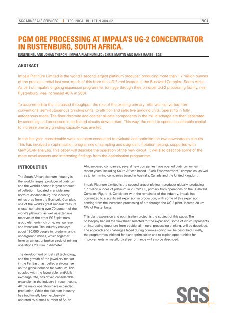
PGM Ore PrOcess<strong>in</strong>G <strong>at</strong> iMPala’s UG-2 cOncentr<strong>at</strong>Or<br />
<strong>in</strong> rUstenbUrG, sOUth africa.<br />
eUGene nel and JOhan therOn - iMPala Pl<strong>at</strong><strong>in</strong>UM ltd.; chris Mart<strong>in</strong> and hans raabe - sGs<br />
abstract<br />
Impala Pl<strong>at</strong><strong>in</strong>um Limited is the world’s second largest pl<strong>at</strong><strong>in</strong>um producer, produc<strong>in</strong>g m<strong>ore</strong> than 1.7 million ounces<br />
of the precious metal last year, much of this from the UG-2 reef loc<strong>at</strong>ed <strong>in</strong> the Bushveld Complex, South Africa.<br />
As part of Impala’s ongo<strong>in</strong>g expansion programme, tonnage thro<strong>ug</strong>h their pr<strong>in</strong>cipal UG-2 <strong>process<strong>in</strong>g</strong> facility, near<br />
Rustenburg, was <strong>in</strong>creased 40% <strong>in</strong> 2001.<br />
To accommod<strong>at</strong>e the <strong>in</strong>creased thro<strong>ug</strong>hput, the role of the exist<strong>in</strong>g primary mills was converted from<br />
conventional semi-autogenous gr<strong>in</strong>d<strong>in</strong>g units, to <strong>at</strong>trition and selective gr<strong>in</strong>d<strong>in</strong>g units, oper<strong>at</strong><strong>in</strong>g <strong>in</strong> fully<br />
autogenous mode. The f<strong>in</strong>er chromite and coarser silic<strong>at</strong>e components <strong>in</strong> the mill discharge are then separ<strong>at</strong>ed<br />
by screen<strong>in</strong>g and processed <strong>in</strong> dedic<strong>at</strong>ed circuits downstream. This way, the need to spend considerable capital<br />
to <strong>in</strong>crease primary gr<strong>in</strong>d<strong>in</strong>g capacity was averted.<br />
In the last year, considerable work has been conducted to evalu<strong>at</strong>e and optimise the two downstream circuits.<br />
This has <strong>in</strong>volved an optimis<strong>at</strong>ion programme of sampl<strong>in</strong>g and diagnostic flot<strong>at</strong>ion test<strong>in</strong>g, supported with<br />
QemSCAN analysis. This paper will describe the oper<strong>at</strong>ion of the new circuit. It will also describe some of the<br />
m<strong>ore</strong> novel aspects and <strong>in</strong>terest<strong>in</strong>g f<strong>in</strong>d<strong>in</strong>gs from the optimis<strong>at</strong>ion programme.<br />
<strong>in</strong>trOdUctiOn<br />
The South African pl<strong>at</strong><strong>in</strong>um <strong>in</strong>dustry is<br />
the world’s largest producer of pl<strong>at</strong><strong>in</strong>um<br />
and the world’s second largest producer<br />
of palladium. Loc<strong>at</strong>ed <strong>in</strong> a wide area<br />
north of Johannesburg, the <strong>in</strong>dustry<br />
m<strong>in</strong>es <strong>ore</strong>s from the Bushveld Complex,<br />
one of the world’s gre<strong>at</strong> m<strong>in</strong>eral treasure<br />
chests, conta<strong>in</strong><strong>in</strong>g over 70 percent of the<br />
world’s pl<strong>at</strong><strong>in</strong>um, as well as extensive<br />
reserves of the other PGE (pl<strong>at</strong><strong>in</strong>um<br />
group elements), chrome, manganese<br />
and vanadium. The <strong>in</strong>dustry employs<br />
about 180,000 people <strong>in</strong>, predom<strong>in</strong>antly,<br />
underground m<strong>in</strong>es, which together<br />
form an almost unbroken circle of m<strong>in</strong><strong>in</strong>g<br />
oper<strong>at</strong>ions 200 km <strong>in</strong> diameter.<br />
The development of fuel cell technology,<br />
and the growth of the jewellery market<br />
<strong>in</strong> the Far East has fuelled a strong rise<br />
on the global demand for pl<strong>at</strong><strong>in</strong>um. This,<br />
coupled with the favourable rand/dollar<br />
exchange r<strong>at</strong>e, has driven considerable<br />
expansion <strong>in</strong> the <strong>in</strong>dustry <strong>in</strong> recent years.<br />
All the major oper<strong>at</strong>ors have expanded<br />
production. While the pl<strong>at</strong><strong>in</strong>um <strong>in</strong>dustry<br />
has traditionally been exclusively<br />
oper<strong>at</strong>ed by a small number of South<br />
African-based companies, several new companies have opened pl<strong>at</strong><strong>in</strong>um m<strong>in</strong>es <strong>in</strong><br />
recent years, <strong>in</strong>clud<strong>in</strong>g South African-based “Black-Empowerment” companies, as well<br />
as junior m<strong>in</strong><strong>in</strong>g companies based <strong>in</strong> Australia, Canada and the United K<strong>in</strong>gdom.<br />
Impala Pl<strong>at</strong><strong>in</strong>um Limited is the second largest pl<strong>at</strong><strong>in</strong>um producer globally, produc<strong>in</strong>g<br />
1.7 million ounces of pl<strong>at</strong><strong>in</strong>um <strong>in</strong> 2002/2003, primary from oper<strong>at</strong>ions on the Bushveld<br />
Complex (Figure 1). Consistent with the rema<strong>in</strong>der of the <strong>in</strong>dustry, Impala has<br />
committed to a significant expansion <strong>in</strong> production, with some of this expansion<br />
com<strong>in</strong>g from the <strong>in</strong>creased <strong>process<strong>in</strong>g</strong> of <strong>ore</strong> thro<strong>ug</strong>h the UG-2 plant, loc<strong>at</strong>ed 20 km<br />
NW of Rustenburg.<br />
This plant expansion and optimis<strong>at</strong>ion project is the subject of this paper. The<br />
philosophy beh<strong>in</strong>d the flowsheet selected for the expansion, some of which represents<br />
an <strong>in</strong>terest<strong>in</strong>g departure from traditional m<strong>in</strong>eral <strong>process<strong>in</strong>g</strong> th<strong>in</strong>k<strong>in</strong>g, will be described.<br />
The approach and challenges faced dur<strong>in</strong>g commission<strong>in</strong>g will be described. F<strong>in</strong>ally,<br />
the programmes <strong>in</strong>iti<strong>at</strong>ed for plant optimis<strong>at</strong>ion and to exploit opportunities for<br />
improvements <strong>in</strong> metallurgical performance will also be described.
<strong>SGS</strong> MINERALS SERVICES TECHNICAL BULLETIN 2004-02<br />
Figure 1: Geographic Loc<strong>at</strong>ion of the Impala Projects and Interests <strong>in</strong> South Africa<br />
UG-2 Ore<br />
UG-2 <strong>ore</strong> is the second most m<strong>in</strong>ed<br />
source of PGE <strong>in</strong> the Bushveld Complex.<br />
Loc<strong>at</strong>ed <strong>in</strong> a reef close to and largely<br />
parallel to the historically-m<strong>in</strong>ed<br />
Merensky Reef, UG-2 has always been<br />
an entic<strong>in</strong>g source of PGE, but<br />
metallurgical difficulties delayed its<br />
extraction and <strong>process<strong>in</strong>g</strong> until rel<strong>at</strong>ively<br />
recently.<br />
UG-2 M<strong>in</strong>eralOGY<br />
hOst M<strong>in</strong>eralOGY<br />
UG-2 <strong>ore</strong> conta<strong>in</strong>s two dom<strong>in</strong>ant suites<br />
of m<strong>in</strong>eralis<strong>at</strong>ion: chromite and<br />
alum<strong>in</strong>ium silic<strong>at</strong>e-based m<strong>in</strong>eralis<strong>at</strong>ion.<br />
The feed to Impala’s UG-2 plant conta<strong>in</strong>s<br />
22 - 24% Cr 2 O 3 , or ro<strong>ug</strong>hly 50%<br />
chromite. The alum<strong>in</strong>ium silic<strong>at</strong>e<br />
m<strong>in</strong>eralis<strong>at</strong>ion <strong>in</strong>cludes primary<br />
magnesium alum<strong>in</strong>o-silic<strong>at</strong>es such as<br />
feldspars, pyroxenes and chlorite, and<br />
hydro thermally-altered silic<strong>at</strong>es such as<br />
amphiboles and talc. Sulphide<br />
m<strong>in</strong>eralis<strong>at</strong>ion is sparse. The feed to<br />
Impala’s UG-2 plant conta<strong>in</strong>s 0.1 to 0.2%<br />
sulphides, these are composed ma<strong>in</strong>ly of<br />
pyrrhotite (ro<strong>ug</strong>hly 50% of all sulphides),<br />
pentlandite (ro<strong>ug</strong>hly 35%) and<br />
chalcopyrite (ro<strong>ug</strong>hly 10%).<br />
PGM M<strong>in</strong>eralOGY<br />
The mix of PGE <strong>in</strong> UG-2 constitutes<br />
ro<strong>ug</strong>hly 45% pl<strong>at</strong><strong>in</strong>um, 25% palladium,<br />
10% rhodium and 15% ruthenium. UG-2<br />
also conta<strong>in</strong>s m<strong>in</strong>or quantities of copper<br />
and nickel sulfides. PGE sulphides<br />
comprise ro<strong>ug</strong>hly 70% of the PGM<br />
(pl<strong>at</strong><strong>in</strong>um group m<strong>in</strong>erals) <strong>in</strong> the UG-2<br />
plant feed, the rema<strong>in</strong>der largely be<strong>in</strong>g<br />
alloys of iron, lead, arsenic and antimony,<br />
or tellurides. As is typical of such <strong>ore</strong>s,<br />
UG-2 pl<strong>at</strong><strong>in</strong>um group m<strong>in</strong>eralis<strong>at</strong>ion is<br />
highly complex.<br />
Figure 2: Composition of fast-flo<strong>at</strong><strong>in</strong>g, slow-flo<strong>at</strong><strong>in</strong>g and unflo<strong>at</strong>ed PGM by m<strong>in</strong>eral type<br />
From the metallurgical perspective,<br />
however, PGM speci<strong>at</strong>ion is a m<strong>in</strong>or<br />
issue as it tends not to dict<strong>at</strong>e<br />
flo<strong>at</strong>ability. For example, QemSCAN<br />
studies of the Impala UG-2 plant feed<br />
have shown th<strong>at</strong> the mix of fast-flo<strong>at</strong><strong>in</strong>g<br />
PGM is similar to th<strong>at</strong> of the slow<br />
flo<strong>at</strong><strong>in</strong>g PGM, and the unflo<strong>at</strong>ed PGM<br />
(Figure 2), <strong>in</strong>dic<strong>at</strong><strong>in</strong>g no clear “hierarchy”<br />
<strong>in</strong> m<strong>in</strong>eral flo<strong>at</strong>ability. This is consistent<br />
with similar studies on the Lac des Iles<br />
circuit (1)<br />
However, largely, the PGM are f<strong>in</strong>ely<br />
dissem<strong>in</strong><strong>at</strong>ed, the average gra<strong>in</strong> size<br />
be<strong>in</strong>g about 10 microns, so th<strong>at</strong> gra<strong>in</strong><br />
size, liber<strong>at</strong>ion and associ<strong>at</strong>ion tend to<br />
dict<strong>at</strong>e m<strong>in</strong>eral flo<strong>at</strong>ability. Pl<strong>at</strong><strong>in</strong>um<br />
group m<strong>in</strong>eral gra<strong>in</strong> size and associ<strong>at</strong>ion<br />
can be split <strong>in</strong>to four c<strong>at</strong>egories:<br />
• Coarse PGM (ro<strong>ug</strong>hly 5% of all PGE)<br />
• PGM associ<strong>at</strong>ed with base metal and<br />
iron sulphides (40%)<br />
• PGM occurr<strong>in</strong>g on host m<strong>in</strong>eral gra<strong>in</strong><br />
boundaries (30%)<br />
• PGM locked <strong>in</strong> silic<strong>at</strong>es (25%)<br />
Those PGM <strong>at</strong>tached to sulphide<br />
m<strong>in</strong>erals can be recovered by<br />
maximis<strong>in</strong>g the flot<strong>at</strong>ion of the base<br />
metal and iron sulphides. Those<br />
occurr<strong>in</strong>g on gra<strong>in</strong> boundaries are<br />
preferentially released dur<strong>in</strong>g gr<strong>in</strong>d<strong>in</strong>g,<br />
so are quite adequ<strong>at</strong>ely liber<strong>at</strong>ed thro<strong>ug</strong>h<br />
a rel<strong>at</strong>ively coarse primary gr<strong>in</strong>d,<br />
particularly if the gr<strong>in</strong>d is oper<strong>at</strong>ed <strong>in</strong> a<br />
m<strong>ore</strong> <strong>at</strong>trition<strong>in</strong>g style. The rema<strong>in</strong><strong>in</strong>g<br />
PGM, locked <strong>in</strong> silic<strong>at</strong>es, are difficult to<br />
liber<strong>at</strong>e, requir<strong>in</strong>g f<strong>in</strong>er liber<strong>at</strong>ion <strong>in</strong> a<br />
secondary mill<strong>in</strong>g step, and longer<br />
ensu<strong>in</strong>g ro<strong>ug</strong>her and cleaner flot<strong>at</strong>ion<br />
times.<br />
2<br />
It is, <strong>in</strong> large part, the n<strong>at</strong>ure of the PGM<br />
occurrences <strong>in</strong> the <strong>ore</strong> th<strong>at</strong> has driven<br />
the philosophy of the adopted flowsheet,<br />
described l<strong>at</strong>er <strong>in</strong> the paper.
<strong>SGS</strong> MINERALS SERVICES TECHNICAL BULLETIN 2004-02<br />
UG-2 Ore PrOcess<strong>in</strong>G<br />
PrObleMs and sOlUtiOns<br />
Historically UG2 <strong>ore</strong> could not be<br />
processed due to the high chrome<br />
content <strong>in</strong> the feed and subsequently<br />
<strong>in</strong> the f<strong>in</strong>al concentr<strong>at</strong>e. Very little of<br />
the chrome itself exhibits any degree of<br />
positive flo<strong>at</strong>ability, but when excessive<br />
gr<strong>in</strong>d<strong>in</strong>g takes place it reports to the f<strong>in</strong>al<br />
concentr<strong>at</strong>e <strong>in</strong> the form of entra<strong>in</strong>ment.<br />
The chrome occurs <strong>in</strong> the <strong>ore</strong> as a<br />
chrome sp<strong>in</strong>el with iron oxide and<br />
only melts <strong>at</strong> temper<strong>at</strong>ures exceed<strong>in</strong>g<br />
1600deg C. In contrast the furnaces<br />
utilized <strong>in</strong> the pl<strong>at</strong><strong>in</strong>um <strong>in</strong>dustry<br />
oper<strong>at</strong>e <strong>at</strong> a much lower temper<strong>at</strong>ure of<br />
1400-1500 deg C. Excessive chrome <strong>in</strong><br />
furnace feeds thus leads to the freez<strong>in</strong>g<br />
of the furnaces reduc<strong>in</strong>g efficiency and<br />
damag<strong>in</strong>g equipment. Thus the<br />
maximum allowable chrome <strong>in</strong> furnace<br />
feed was historically limited to about<br />
1 %. Consider<strong>in</strong>g th<strong>at</strong> chrome <strong>in</strong><br />
concentr<strong>at</strong>e for UG2 plants <strong>in</strong> general<br />
were <strong>in</strong> the region of 3-4% it was<br />
extremely difficult to ma<strong>in</strong>ta<strong>in</strong> high UG2<br />
<strong>process<strong>in</strong>g</strong> capacities.<br />
Subsequent developments <strong>in</strong> furnace<br />
technology has allowed concentr<strong>at</strong>es<br />
with a chrome content of up to 1.8%<br />
be<strong>in</strong>g processed and further test work<br />
is underway to push this boundary<br />
even further. In addition UG2<br />
<strong>process<strong>in</strong>g</strong> has been ref<strong>in</strong>ed to the po<strong>in</strong>t<br />
where concentr<strong>at</strong>es with chrome grades<br />
of less than 2.5% are be<strong>in</strong>g achieved<br />
regularly, as will be seen from this paper.<br />
Such chrome levels represent less than<br />
0.3% misplacement of the chrome <strong>in</strong> the<br />
feed, to the f<strong>in</strong>al concentr<strong>at</strong>e.<br />
iMPala UG-2 Plant histOrY<br />
UG 2 was first processed by Impala <strong>at</strong><br />
its Rustenburg oper<strong>at</strong>ions <strong>in</strong> 1991 when<br />
the first phase of the current UG2 plant<br />
was commissioned. The circuit (Figure<br />
3) consisted of two parallel l<strong>in</strong>es, each<br />
employ<strong>in</strong>g s<strong>in</strong>gle-stage primary mill<strong>in</strong>g<br />
followed by ro<strong>ug</strong>her and cleaner flot<strong>at</strong>ion<br />
us<strong>in</strong>g Wemco flot<strong>at</strong>ion cells, the tails<br />
of which were thickened and pumped<br />
to a tail<strong>in</strong>gs dam. The mill<strong>in</strong>g approach,<br />
termed run-of-m<strong>in</strong>e ball mill<strong>in</strong>g employed<br />
mills receiv<strong>in</strong>g run-of-m<strong>in</strong>e m<strong>at</strong>erial,<br />
oper<strong>at</strong><strong>in</strong>g <strong>at</strong> 85% critical speed and us<strong>in</strong>g<br />
Figure 3: MF1 UG2 plant setup (1991-1994)<br />
high ball loads. The flot<strong>at</strong>ion section was a standard ro<strong>ug</strong>her/cleaner/re-cleaner<br />
cascade configur<strong>at</strong>ion with f<strong>in</strong>al concentr<strong>at</strong>e be<strong>in</strong>g pulled from the re-cleaner cells. This<br />
“mill-flo<strong>at</strong>” configur<strong>at</strong>ion is commonly termed MF1 <strong>in</strong> South Africa. The primary gr<strong>in</strong>d<br />
was coarse limit<strong>in</strong>g the risk of chrome entra<strong>in</strong>ment <strong>in</strong>to the f<strong>in</strong>al concentr<strong>at</strong>e, but also<br />
limit<strong>in</strong>g PGM recovery due to its <strong>in</strong>herent tendency not to recover m<strong>ore</strong> f<strong>in</strong>ely<br />
dissem<strong>in</strong><strong>at</strong>ed, silic<strong>at</strong>e-associ<strong>at</strong>ion PGM.<br />
Consequently, <strong>in</strong> 1994 it was decided to improve PGM recoveries by <strong>in</strong>stall<strong>in</strong>g regr<strong>in</strong>d<br />
mill<strong>in</strong>g and “secondary ro<strong>ug</strong>her/cleaner flot<strong>at</strong>ion, on the exist<strong>in</strong>g plant tails (MF2 type<br />
circuit - Figure 4). The <strong>in</strong>creased f<strong>in</strong>eness of gr<strong>in</strong>d obta<strong>in</strong>ed could have led to <strong>in</strong>creased<br />
chrome grades and subsequent furnace problems as mentioned earlier but<br />
improvements <strong>in</strong> furnace design allowed for this to be neg<strong>at</strong>ed. By this time the<br />
Figure 4 MF2 circuit <strong>at</strong> Impala’s UG2 plant (1994-2001)<br />
<strong>process<strong>in</strong>g</strong> of UG2 <strong>ore</strong>s had also become common practice and the <strong>in</strong>dustry as a<br />
whole had developed improved <strong>process<strong>in</strong>g</strong> practices.<br />
Str<strong>at</strong>egically it became apparent th<strong>at</strong> an <strong>in</strong>creased amount of UG2 <strong>ore</strong> would have to<br />
be processed to ma<strong>in</strong>ta<strong>in</strong> overall PGM output, as the exist<strong>in</strong>g reserves of Merensky<br />
reef low <strong>in</strong> chromite were slowly be<strong>in</strong>g depleted while vast UG2 resources were still<br />
available. Subsequently the decision was made to <strong>in</strong>crease the capacity <strong>at</strong> the UG2<br />
plant and <strong>at</strong> the same time <strong>at</strong>tempt to improve recovery <strong>at</strong> acceptable chrome content<br />
<strong>in</strong> f<strong>in</strong>al concentr<strong>at</strong>e. This prompted <strong>in</strong>iti<strong>at</strong>ion of the UG2 <strong>ore</strong> separ<strong>at</strong>ion project.<br />
3
<strong>SGS</strong> MINERALS SERVICES TECHNICAL BULLETIN 2004-02<br />
Figure 5 UG2 <strong>ore</strong> separ<strong>at</strong>ion basic flow sheet<br />
Ore sePar<strong>at</strong>iOn PrOJect<br />
The concept beh<strong>in</strong>d the UG2 <strong>ore</strong><br />
separ<strong>at</strong>ion project was derived from<br />
the unique n<strong>at</strong>ure of UG-2 m<strong>in</strong>eralogy,<br />
namely:<br />
• Most PGM rich m<strong>in</strong>erals <strong>in</strong> the<br />
run-of-m<strong>in</strong>e <strong>ore</strong> are associ<strong>at</strong>ed with<br />
the chrome-rich fraction <strong>in</strong> the <strong>ore</strong><br />
(the UG-2 reef itself). The friable n<strong>at</strong>ure<br />
of the <strong>ore</strong> and the <strong>in</strong>tergranular<br />
loc<strong>at</strong>ion of most of the PGM <strong>in</strong> this<br />
m<strong>at</strong>erial means th<strong>at</strong> after underground<br />
blast<strong>in</strong>g and primary mill<strong>in</strong>g, this<br />
fraction is rel<strong>at</strong>ively f<strong>in</strong>e and the PGM<br />
well-liber<strong>at</strong>ed.<br />
• The silic<strong>at</strong>e rich fractions <strong>in</strong> the plant<br />
feed (ma<strong>in</strong>ly norite, anorthosite etc)<br />
conta<strong>in</strong> a much lower PGM content as<br />
most of this m<strong>at</strong>erial orig<strong>in</strong><strong>at</strong>es from<br />
the hang<strong>in</strong>g or footwall of the stope<br />
face.<br />
The object, theref<strong>ore</strong>, of the primary<br />
gr<strong>in</strong>d<strong>in</strong>g and classific<strong>at</strong>ion circuit was<br />
to maximise exploit<strong>at</strong>ion these<br />
m<strong>in</strong>eralogical characteristics. The<br />
difference <strong>in</strong> breakage characteristics of<br />
the two <strong>ore</strong> components is best<br />
exploited by fully autogenous gr<strong>in</strong>d<strong>in</strong>g,<br />
r<strong>at</strong>her than semi-autogenous gr<strong>in</strong>d<strong>in</strong>g.<br />
This also allows for crush<strong>in</strong>g of the<br />
sizeable stream of silic<strong>at</strong>e pebbles<br />
discharg<strong>in</strong>g from the autogenous mills,<br />
without risk of crusher damage thro<strong>ug</strong>h<br />
miss-directed gr<strong>in</strong>d<strong>in</strong>g media. This way,<br />
it was believed th<strong>at</strong> the primary mill<br />
thro<strong>ug</strong>hput could be <strong>in</strong>creased by about<br />
40%, from 350kt/m to 490kt/m.<br />
This, theref<strong>ore</strong>, represented a rare case<br />
when conversion of primary mills from<br />
semi-autogenous to fully-autogenous<br />
mode had the potential to substantially<br />
<strong>in</strong>crease thro<strong>ug</strong>hput.<br />
The result<strong>in</strong>g two products from the<br />
circuit, namely the f<strong>in</strong>er chrome/PGMrich<br />
m<strong>at</strong>erial, and the coarser silic<strong>at</strong>e<br />
m<strong>at</strong>erials could be tre<strong>at</strong>ed <strong>in</strong> separ<strong>at</strong>e<br />
circuits. This allowed for the tailor<strong>in</strong>g of<br />
the gr<strong>in</strong>d<strong>in</strong>g circuits, flot<strong>at</strong>ion circuits<br />
and reagent suites to the particular<br />
m<strong>in</strong>eralogy of each stream, so ensur<strong>in</strong>g<br />
optimal extraction of the conta<strong>in</strong>ed PGM.<br />
In 1999, Johannesburg-based M<strong>in</strong>tek<br />
launched an extensive pilot plant<br />
campaign <strong>in</strong> order to evalu<strong>at</strong>e the poten-<br />
tial benefits of such a circuit. The results<br />
from these studies were sufficiently<br />
encourag<strong>in</strong>g to prompt Impala to<br />
construct and commission the modified<br />
circuit, which started up <strong>in</strong> 2001.<br />
PrOcess descriPtiOn<br />
Primary autogenous mill<strong>in</strong>g, screen<strong>in</strong>g<br />
and crush<strong>in</strong>g.<br />
Two 6.4m x 4.9m primary mills (fully<br />
autogenous) are oper<strong>at</strong>ed <strong>in</strong> parallel <strong>at</strong><br />
a feed r<strong>at</strong>e of 380 t/hr run of m<strong>in</strong>e <strong>ore</strong>.<br />
A discharge mill trommel on each mill<br />
cuts <strong>at</strong> 12mm with the oversize be<strong>in</strong>g<br />
crushed thro<strong>ug</strong>h a closed circuit cone<br />
crush<strong>in</strong>g plant. The m<strong>in</strong>us 12mm fraction<br />
is screened <strong>at</strong> 600 µm with the oversize<br />
recomb<strong>in</strong><strong>in</strong>g with the crushed product to<br />
form the low grade circuit feed. The undersize<br />
from the classify<strong>in</strong>g screens form<br />
the feed to the high grade circuit.<br />
Secondary mill<strong>in</strong>g of silic<strong>at</strong>e rich product<br />
from primary mills (Low grade mill)<br />
4<br />
The low grade mill<strong>in</strong>g circuit comprises<br />
a 9.3m x 6.1m ball mill equipped with a<br />
6.1MW motor, and oper<strong>at</strong><strong>in</strong>g <strong>in</strong> closed<br />
circuit with a cluster of 500mm cyclones.
<strong>SGS</strong> MINERALS SERVICES TECHNICAL BULLETIN 2004-02<br />
Typical gr<strong>in</strong>ds of 65% pass<strong>in</strong>g 75µm are<br />
achieved. High chrome gr<strong>in</strong>d<strong>in</strong>g media<br />
(50mm) are used <strong>at</strong> a fill<strong>in</strong>g degree <strong>in</strong> the<br />
region of 25-28%.<br />
Flot<strong>at</strong>ion of silic<strong>at</strong>e rich stream<br />
The feed to this section oper<strong>at</strong>es <strong>at</strong> a<br />
grade almost half th<strong>at</strong> of plant feed with<br />
a chrome content of 12-14% compared<br />
to plant feed chrome content of 20%.<br />
The circuit is configured <strong>in</strong> a conventional<br />
ro<strong>ug</strong>her/cleaner/re-cleaner configur<strong>at</strong>ion,<br />
with the cleaner tail <strong>in</strong> closed circuit with<br />
ro<strong>ug</strong>her feed and re-cleaner tails form<strong>in</strong>g<br />
part of the cleaner feed. The flot<strong>at</strong>ion<br />
equipment used (B<strong>at</strong>eman tank cells)<br />
range <strong>in</strong> size from 10 to 50 cubic meters.<br />
At the time of start-up, reagents used <strong>in</strong><br />
this circuit <strong>in</strong>cluded sodium isobutyl<br />
xanth<strong>at</strong>e, sodium dithiophosph<strong>at</strong>e,<br />
copper sulph<strong>at</strong>e to activ<strong>at</strong>e the iron<br />
sulphides, a polyglycol ether frother and<br />
a CMC-based polymeric depressant.<br />
Primary flot<strong>at</strong>ion of chromite rich (high<br />
grade) stream<br />
The basic process flow for the high grade<br />
flo<strong>at</strong> is similar to the low grade circuit<br />
altho<strong>ug</strong>h the exist<strong>in</strong>g Wemco cells are<br />
still be<strong>in</strong>g used <strong>in</strong> conjunction with two<br />
newly <strong>in</strong>stalled B<strong>at</strong>eman tank cells.<br />
Oversized mechanisms (Wemco 190’s)<br />
are used <strong>in</strong> the Wemco 164 ro<strong>ug</strong>her cells<br />
to ensure they can be started under load.<br />
Flo<strong>at</strong> feed to this section is quite coarse<br />
<strong>at</strong> 30% -75um, rich <strong>in</strong> high SG chrome<br />
and has a pulp density of 1.65 g/cm 3 . The<br />
cleaner tails are directed to the head of<br />
the primary ro<strong>ug</strong>her banks with ro<strong>ug</strong>her<br />
tails form<strong>in</strong>g the feed to the secondary/<br />
regr<strong>in</strong>d mill. Altho<strong>ug</strong>h the suite of<br />
reagents used <strong>in</strong> this circuit was, <strong>at</strong><br />
start-up similar to the low grade circuit,<br />
considerably m<strong>ore</strong> reagent is used <strong>in</strong><br />
this circuit.<br />
Regr<strong>in</strong>d of chromite rich (high grade)<br />
stream<br />
Regr<strong>in</strong>d<strong>in</strong>g of both primary flo<strong>at</strong> ro<strong>ug</strong>her<br />
tail streams is achieved thro<strong>ug</strong>h a s<strong>in</strong>gle<br />
ball mill identical <strong>in</strong> size to the low grade<br />
mill, and also equipped with a 6.1MW<br />
motor. Gr<strong>in</strong>d<strong>in</strong>g media consists of 35mm<br />
high chrome steel balls with a fill<strong>in</strong>g<br />
degree of 25-28%. Initially this circuit<br />
was run <strong>in</strong> closed circuit with a cluster<br />
of cyclones, but was recently modified to<br />
an open circuit with two stage<br />
classific<strong>at</strong>ion, as described <strong>in</strong> m<strong>ore</strong><br />
detailed l<strong>at</strong>er <strong>in</strong> the paper. Product from<br />
this circuit is ro<strong>ug</strong>hly 65% pass<strong>in</strong>g 75<br />
microns and controlled <strong>at</strong> a density of<br />
1.45 g/cm 3 .<br />
Secondary flot<strong>at</strong>ion of chromite rich (high<br />
grade) stream<br />
The secondary high grade flot<strong>at</strong>ion<br />
section follows an almost identical<br />
configur<strong>at</strong>ion to the primary flo<strong>at</strong><br />
altho<strong>ug</strong>h smaller 144 (8.5 m 3 ) Wemco<br />
cells are used. The PGM targeted <strong>in</strong> this<br />
flo<strong>at</strong> are somewh<strong>at</strong> f<strong>in</strong>er and/or m<strong>ore</strong><br />
locked than those <strong>in</strong> the primary ro<strong>ug</strong>her<br />
flot<strong>at</strong>ion circuit, so the k<strong>in</strong>etics tend to<br />
be somewh<strong>at</strong> slower. Consequently,<br />
the residence time <strong>in</strong> this circuit is<br />
somewh<strong>at</strong> longer.<br />
cOMMissiOn<strong>in</strong>G issUes<br />
A number of mechanical as well as<br />
metallurgical problems were experienced<br />
dur<strong>in</strong>g the changeover from conventional<br />
MF2 mill<strong>in</strong>g to the High grade/ Low<br />
grade split oper<strong>at</strong>ion. Most of these<br />
were centered on the mill<strong>in</strong>g circuits,<br />
the most prom<strong>in</strong>ent ones be<strong>in</strong>g the<br />
follow<strong>in</strong>g:<br />
Primary autogenous mill control<br />
A number of problems were experienced<br />
with the mill pebble ports fail<strong>in</strong>g result<strong>in</strong>g<br />
<strong>in</strong> oversized m<strong>at</strong>erial report<strong>in</strong>g to the<br />
crushers. It was also important to get<br />
the right size pebble ports <strong>in</strong> order to<br />
ma<strong>in</strong>ta<strong>in</strong> thro<strong>ug</strong>hput thro<strong>ug</strong>h the mill and<br />
<strong>at</strong> the same time ma<strong>in</strong>ta<strong>in</strong> mill load.<br />
For the oper<strong>at</strong>ions personnel there was<br />
a steep learn<strong>in</strong>g curve oper<strong>at</strong><strong>in</strong>g an<br />
autogenous mill compared to the<br />
previous run-of-m<strong>in</strong>e ball mills. It was<br />
found th<strong>at</strong> mill power draw fluctu<strong>at</strong>ed<br />
due to large fluctu<strong>at</strong>ions <strong>in</strong> mill feed size<br />
distribution. Various methods were<br />
<strong>at</strong>tempted to neg<strong>at</strong>e this but<br />
eventually the most effective was for the<br />
mill oper<strong>at</strong>ors to visually select different<br />
mill feeders <strong>in</strong> order to obta<strong>in</strong> coarser<br />
feed sizes to the mills. Ultim<strong>at</strong>ely,<br />
oper<strong>at</strong>ion proved too complex for manual<br />
control, and an expert system was<br />
successfully developed by Impala staff to<br />
control mill oper<strong>at</strong>ion.<br />
Flot<strong>at</strong>ion circuit sand<strong>in</strong>g, chokes and<br />
abrasion issues.<br />
The ma<strong>in</strong> mechanical and oper<strong>at</strong>ional<br />
issues encountered were as a result of<br />
the coarse primary gr<strong>in</strong>ds as well as the<br />
abrasive n<strong>at</strong>ure of the chromite <strong>ore</strong>. This<br />
led to a number of l<strong>in</strong>e chokes as well<br />
as sand<strong>in</strong>g up of flo<strong>at</strong> banks. As a result<br />
flo<strong>at</strong> densities of 1.65 are ma<strong>in</strong>ta<strong>in</strong>ed <strong>in</strong><br />
the primary section with densities of 1.45<br />
on the secondary flo<strong>at</strong> <strong>in</strong> order to keep<br />
the particles <strong>in</strong> suspension. F<strong>in</strong>al tail<strong>in</strong>gs<br />
are also kept <strong>at</strong> a slurry density of 1.6 to<br />
ensure the correct pump<strong>in</strong>g<br />
efficiencies are ma<strong>in</strong>ta<strong>in</strong>ed. However<br />
due to the abrasiveness of the chromite<br />
particles regular ma<strong>in</strong>tenance and<br />
changeovers is still required. This was<br />
also very evident <strong>in</strong> the mill l<strong>in</strong>er lives of<br />
the regr<strong>in</strong>d mills.<br />
MetallUrGical PerfOrMance<br />
The changeover to the new <strong>ore</strong><br />
separ<strong>at</strong>ion circuit was motiv<strong>at</strong>ed based<br />
ma<strong>in</strong>ly on <strong>in</strong>creased thro<strong>ug</strong>hput, but,<br />
secondarily, on <strong>in</strong>creased recoveries<br />
believed to be obta<strong>in</strong>able from this type<br />
of <strong>ore</strong> split. Once steady mechanical<br />
oper<strong>at</strong>ions were established, the design<br />
thro<strong>ug</strong>hput of 380t/hr per mill was<br />
consistently achieved. Even tho<strong>ug</strong>h the<br />
required tonnage <strong>in</strong>crease was realized,<br />
the <strong>in</strong>crease <strong>in</strong> recovery could never be<br />
obta<strong>in</strong>ed. Plant tails grades rema<strong>in</strong>ed<br />
close to 1g/t (comb<strong>in</strong>ed Pt, Pd, Au and<br />
Rh), well above the 0.75 g/t target.<br />
Consequently, Impala decided to embark<br />
on a structured process optimiz<strong>at</strong>ion<br />
project <strong>in</strong> conjunction with numerous<br />
technology partners <strong>in</strong>clud<strong>in</strong>g <strong>SGS</strong><br />
Lakefield, H<strong>at</strong>ch Africa and M<strong>in</strong>tek.<br />
the strUctUred<br />
OPtiMis<strong>at</strong>iOn PrOGraMMe<br />
5<br />
All too often, optimis<strong>at</strong>ion efforts<br />
conducted after the start-up of complex<br />
m<strong>in</strong>eral <strong>process<strong>in</strong>g</strong> circuits range from<br />
disorganised to chaotic, particularly when<br />
plant management are under pressure<br />
to rapidly achieve results. Considerable<br />
effort, and often extensive resources are<br />
devoted to solv<strong>in</strong>g seemly <strong>in</strong>tangible
<strong>SGS</strong> MINERALS SERVICES TECHNICAL BULLETIN 2004-02<br />
problems, a plethora of metallurgists and<br />
consultants all eagerly, and<br />
randomly, search<strong>in</strong>g for the holy grail<br />
of the metallurgical fix – th<strong>at</strong> which will<br />
solve the problems overnight. This is<br />
not only <strong>in</strong>efficient, but also leads to<br />
considerable confusion, stemm<strong>in</strong>g from<br />
the wide variety of “solutions” proposed,<br />
often based on <strong>in</strong>dependently collected<br />
d<strong>at</strong>asets and observ<strong>at</strong>ions.<br />
Structured optimis<strong>at</strong>ion programmes<br />
were developed by two of the authors<br />
to diffuse such situ<strong>at</strong>ions, dur<strong>in</strong>g the<br />
post-commission<strong>in</strong>g optimis<strong>at</strong>ion of<br />
several South African PGM circuits <strong>in</strong> the<br />
early 1990’s. The object of the structured<br />
optimis<strong>at</strong>ion programme is to maximise<br />
the efficiency of the technical resources<br />
directed to optimise the plant, by<br />
focus<strong>in</strong>g the effort, adher<strong>in</strong>g to simple<br />
m<strong>in</strong>eral <strong>process<strong>in</strong>g</strong> “basics”, but also<br />
be<strong>in</strong>g comprehensive <strong>in</strong> the approach.<br />
Broadly, the programmes consist of<br />
three different phases:<br />
Phase 1:<br />
• D<strong>at</strong>a g<strong>at</strong>her<strong>in</strong>g,<br />
• Identific<strong>at</strong>ion and implement<strong>at</strong>ion of<br />
low-cost, rapidly eng<strong>in</strong>eered opportunities<br />
for process improvements, and,<br />
• Identific<strong>at</strong>ion of opportunities for<br />
low-risk, high-return capital projects to<br />
achieve further improvements <strong>in</strong> plant<br />
performance.<br />
Phase 2:<br />
• Evalu<strong>at</strong>ion of candid<strong>at</strong>e capital projects.<br />
• Risk management of the capital<br />
projects.<br />
Phase 3:<br />
• Implement<strong>at</strong>ion of capital projects.<br />
• Follow-up d<strong>at</strong>a g<strong>at</strong>her<strong>in</strong>g.<br />
Prior to the presently described<br />
optimis<strong>at</strong>ion programme, such projects<br />
have successfully optimised m<strong>in</strong>eral<br />
<strong>process<strong>in</strong>g</strong> circuits <strong>in</strong> the pl<strong>at</strong><strong>in</strong>um<br />
<strong>in</strong>dustry <strong>in</strong> South Africa, <strong>in</strong> the silver<br />
<strong>in</strong>dustry <strong>in</strong> the United St<strong>at</strong>es and most<br />
recently <strong>at</strong> the Lac des Iles oper<strong>at</strong>ion <strong>in</strong><br />
Ontario (1). In each case the programme<br />
smoothed and, most likely, gre<strong>at</strong>ly<br />
acceler<strong>at</strong>ed the optimis<strong>at</strong>ion of the<br />
respective oper<strong>at</strong>ions – substantial<br />
<strong>in</strong>creases <strong>in</strong> plant concentr<strong>at</strong>e grades<br />
and/or recoveries achieved <strong>in</strong> each case.<br />
Phase 1<br />
activities dUr<strong>in</strong>G Phase 1<br />
24 hour composite d<strong>at</strong>a g<strong>at</strong>her<strong>in</strong>g.<br />
A suite of 24 hour composites were<br />
collected daily by shift personnel, the<br />
objective be<strong>in</strong>g to be able to cre<strong>at</strong>e a<br />
daily mass balance of each stage of<br />
flot<strong>at</strong>ion <strong>in</strong> the entire circuit. This served<br />
several purposes:<br />
• It provided a historically robust d<strong>at</strong>a<br />
popul<strong>at</strong>ion on the broad mass balance<br />
of the circuit, enabl<strong>in</strong>g the metallurgists<br />
to identify the best- and worst-perform<strong>in</strong>g<br />
parts of the circuit, so help<strong>in</strong>g to<br />
focus the m<strong>ore</strong> detailed d<strong>at</strong>a-g<strong>at</strong>her<strong>in</strong>g<br />
efforts.<br />
• It provided a “mother d<strong>at</strong>a popul<strong>at</strong>ion”<br />
aga<strong>in</strong>st which <strong>in</strong>dividual survey d<strong>at</strong>a<br />
could be evalu<strong>at</strong>ed for long-term<br />
represent<strong>at</strong>ivity.<br />
• It cre<strong>at</strong>ed samples for size-by-size<br />
diagnostic metallurgy.<br />
Detailed Surveys<br />
Surveys were conducted on selected<br />
parts of the plant, where the gre<strong>at</strong>est<br />
potential for benefit was perceived<br />
to exist. Initially, the plan was to<br />
conduct detailed surveys on all sections<br />
<strong>in</strong> the plant. However, evidence<br />
aris<strong>in</strong>g from the other work, and the<br />
sheer complexity associ<strong>at</strong>ed with<br />
survey<strong>in</strong>g such a large circuit made this<br />
both unnecessary and impossible. Where<br />
Figure 6: Change <strong>in</strong> UG-2 Plant Tails Assays, January – June 2003<br />
conducted, the surveys:<br />
• Cre<strong>at</strong>ed k<strong>in</strong>etics d<strong>at</strong>a, <strong>in</strong>clud<strong>in</strong>g size-bysize<br />
k<strong>in</strong>etics d<strong>at</strong>a on banks of flot<strong>at</strong>ion<br />
cells <strong>in</strong> the circuit.<br />
• Cre<strong>at</strong>ed complete w<strong>at</strong>er and solids<br />
mass balances, us<strong>in</strong>g Bilm<strong>at</strong> software.<br />
• Established typical oper<strong>at</strong><strong>in</strong>g practices<br />
thro<strong>ug</strong>hout this part of the circuit,<br />
<strong>in</strong>clud<strong>in</strong>g cell oper<strong>at</strong>ion, reagent<br />
dosage, motor power draws etc.<br />
Examples of the d<strong>at</strong>a gener<strong>at</strong>ed from<br />
studies of the high grade primary<br />
ro<strong>ug</strong>her circuit, are shown <strong>in</strong> Table 1.<br />
Flot<strong>at</strong>ion diagnostic studies<br />
Campaigns of flot<strong>at</strong>ion tests were<br />
implemented on selected streams.<br />
Such tests were conducted numerous<br />
times for each stream. This not only<br />
built up a robust, historically-based d<strong>at</strong>a<br />
popul<strong>at</strong>ion, but it also served as an<br />
excellent tra<strong>in</strong><strong>in</strong>g tool for the on-site<br />
technicians, who became highly adept<br />
<strong>at</strong> flo<strong>at</strong><strong>in</strong>g key streams <strong>in</strong> the plant (a<br />
skill not usually present <strong>in</strong> a newly<br />
commissioned plant). This <strong>in</strong> turn<br />
improved the quality of reagent and<br />
gr<strong>in</strong>d<strong>in</strong>g optimis<strong>at</strong>ion testwork,<br />
implemented on an ongo<strong>in</strong>g basis as<br />
d<strong>at</strong>a were g<strong>at</strong>hered from the surveys<br />
and 24-hour sampl<strong>in</strong>g campaigns.<br />
6
<strong>SGS</strong> MINERALS SERVICES TECHNICAL BULLETIN 2004-02<br />
• Ro<strong>ug</strong>her Feed: These studies were<br />
<strong>in</strong>iti<strong>at</strong>ed to cre<strong>at</strong>e an understand<strong>in</strong>g of<br />
the mass pull/recovery rel<strong>at</strong>ionships of<br />
the ro<strong>ug</strong>her flot<strong>at</strong>ion circuits (past<br />
experience had shown th<strong>at</strong> m<strong>at</strong>erial<br />
transfer problems associ<strong>at</strong>ed with<br />
talcous PGM concentr<strong>at</strong>es often lead<br />
to less than optimal flot<strong>at</strong>ion mass pull<br />
r<strong>at</strong>es). The labor<strong>at</strong>ory d<strong>at</strong>a could then<br />
be compared with the d<strong>at</strong>a from the<br />
24-hour composite programme and the<br />
detailed surveys to identify the<br />
potential for improved recoveries<br />
associ<strong>at</strong>ed with elim<strong>in</strong><strong>at</strong><strong>in</strong>g<br />
pump<strong>in</strong>g restrictions and so pull<strong>in</strong>g<br />
m<strong>ore</strong> concentr<strong>at</strong>e.<br />
• Ro<strong>ug</strong>her Tails: Flot<strong>at</strong>ion tests on the<br />
tails were as powerful as those on<br />
the feed streams, as they provided<br />
a direct <strong>in</strong>dic<strong>at</strong>ion of the “flo<strong>at</strong>able”<br />
values be<strong>in</strong>g lost to tails. These tests<br />
were conducted on all tails streams,<br />
particularly those th<strong>at</strong> are delivered out<br />
of the plant (altho<strong>ug</strong>h the high grade<br />
primary ro<strong>ug</strong>her tails stream, feed<strong>in</strong>g<br />
the regr<strong>in</strong>d mill<strong>in</strong>g circuit was also<br />
studied).<br />
• Cleaner Tails: Completeness of flot<strong>at</strong>ion<br />
tests were also conducted on cleaner<br />
tails streams.<br />
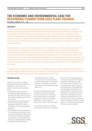
resUlts<br />
Several quick-fixes were identified dur<strong>in</strong>g<br />
this phase, perhaps the most significant<br />
be<strong>in</strong>g optimis<strong>at</strong>ion of the high grade<br />
regr<strong>in</strong>d cyclones <strong>in</strong> January, and<br />
establish<strong>in</strong>g a different reagent suite <strong>in</strong><br />
May, to better balance mass pull r<strong>at</strong>es.<br />
The results are shown <strong>in</strong> terms of<br />
changes <strong>in</strong> plant tail<strong>in</strong>gs assays, <strong>in</strong><br />
Figure 6.<br />
Dur<strong>in</strong>g the year, recoveries improved<br />
from 71% <strong>in</strong> the fourth quarter of 2002<br />
to an average of over 75% for the period<br />
from June to September 2003.<br />
Phase 1 also identified three significant<br />
candid<strong>at</strong>e long-term fixes, all perta<strong>in</strong><strong>in</strong>g<br />
to the high grade circuit, losses from<br />
which contribute m<strong>ore</strong> than 79% of the<br />
PGE sent to the tail<strong>in</strong>gs impoundment:<br />
Figure 7: Size-by-Size PGM Recovery, High-grade Secondary Ro<strong>ug</strong>her Flot<strong>at</strong>ion<br />
hiGh Grade reGr<strong>in</strong>d circUit OPtiMis<strong>at</strong>iOn: seMi-OPen circUit reGr<strong>in</strong>d<strong>in</strong>G<br />
The two predom<strong>in</strong>ant phases <strong>in</strong> UG-2 <strong>ore</strong>s are high SG chromitite and lower SG silic<strong>at</strong>e<br />
m<strong>in</strong>erals. PGM associ<strong>at</strong>ed with chromitite are almost universally found along gra<strong>in</strong><br />
boundaries, and the friable n<strong>at</strong>ure of the chromitite gra<strong>in</strong> structure means th<strong>at</strong> these<br />
PGM are readily liber<strong>at</strong>ed with rel<strong>at</strong>ively little gr<strong>in</strong>d<strong>in</strong>g. Conversely, the PGM associ<strong>at</strong>ed<br />
with the silic<strong>at</strong>e phases are m<strong>ore</strong> commonly <strong>in</strong>tergrown <strong>in</strong>to the host silic<strong>at</strong>e gra<strong>in</strong>s,<br />
often be<strong>in</strong>g completely locked <strong>in</strong> the silic<strong>at</strong>e phase. As described earlier <strong>in</strong> this paper, it<br />
is these PGM th<strong>at</strong> need to be liber<strong>at</strong>ed us<strong>in</strong>g the high-grade regr<strong>in</strong>d mill<strong>in</strong>g circuit, as<br />
reflected by the secondary ro<strong>ug</strong>her size-by-size recovery rel<strong>at</strong>ionship shown <strong>in</strong> Figure<br />
7. Clearly, the objective of the regr<strong>in</strong>d circuit would be to maximise the production of<br />
flo<strong>at</strong>able, m<strong>in</strong>us-38 micron PGE.<br />
However, closed circuit regr<strong>in</strong>d<strong>in</strong>g merely led to accumul<strong>at</strong>ion of the dense, PGMbarren<br />
chromite <strong>in</strong> the circul<strong>at</strong><strong>in</strong>g load, lead<strong>in</strong>g to wasted energy and an <strong>in</strong>creased<br />
tendency for the PGM-rich silic<strong>at</strong>e m<strong>in</strong>erals to by-pass the gr<strong>in</strong>d<strong>in</strong>g circuit completely.<br />
The effect of this was clearly demonstr<strong>at</strong>ed thro<strong>ug</strong>h the size distribution of the chrome<br />
and PGM <strong>in</strong> the high-grade regr<strong>in</strong>d circuit feed and product, shown below (Figures 8<br />
and 9). Note how the abundance of chrome <strong>in</strong> the –38 micron fraction has risen by<br />
24%. Conversely, note how the abundance of PGM <strong>in</strong> the –38 micron fraction rose<br />
only marg<strong>in</strong>ally, by 3.5%. The circuit did little to liber<strong>at</strong>e PGM, and cre<strong>at</strong>ed significant<br />
ultra-f<strong>in</strong>e chrome <strong>in</strong>creas<strong>in</strong>g the entra<strong>in</strong>ment of chrome to the f<strong>in</strong>al concentr<strong>at</strong>e.<br />
Figure 8: Distribution of PGM to the +75, 38-75 and –75 micron Size Fractions<br />
7
<strong>SGS</strong> MINERALS SERVICES TECHNICAL BULLETIN 2004-02<br />
Clearly this is one of those rare cases<br />
where closed circuit regr<strong>in</strong>d mill<strong>in</strong>g does<br />
not improve gr<strong>in</strong>d<strong>in</strong>g circuit efficiency,<br />
<strong>at</strong> least as measured by the degree of<br />
<strong>in</strong>creased liber<strong>at</strong>ion of the values.<br />
Figure 9: Distribution of Chrome to the +75, 38-75 and –75 micron Size Fractions<br />
Table 1: Mass and Metallurgical Balance from Survey<strong>in</strong>g the Impala UG-2 High Grade Ro<strong>ug</strong>her Circuit, show orig<strong>in</strong>al and Bilm<strong>at</strong>balanced d<strong>at</strong>a.<br />
sUrveY #2 - PriMarY hG circUit, JUlY 8, 03<br />
sectiOn 1<br />
saMPles d<strong>at</strong>a <strong>in</strong>PUt bilM<strong>at</strong><br />
assaY calcUl<strong>at</strong>ed resUlts<br />
actUal <strong>in</strong>PUt tO bilM<strong>at</strong> WeiGht rec<br />
PGM cr 2 O 3 PGM cr 2 O 3 PGM cr 2 O 3 PGM<br />
No. Description g/t % g/t % % g/t % %<br />
1 Prim HG Feed - Section 1 4.86 23.2 4.86 23.2 100.0% 4.84 21.9 100.0%<br />
2 Prim HG Tank Cell Fd - Section 1 5.09 20.8 5.09 20.8 101.5% 4.95 21.7 103.9%<br />
3 Prim HG Tank Cell Conc - Section 1 230.0 2.93 230 2.93 0.58% 237 2.89 28.3%<br />
34 Prim HG Tank Cell-2 Tail - Section 1 3.63 20.0 3.63 20.0 100.9% 3.62 21.8 75.6%<br />
35 Prim HG Rghr Cell 1 Conc - Section 1 76.8 4.86 76.8 4.86 0.53% 77 5.08 8.4%<br />
36 Prim HG Rghr Cell 1 Tail - Section 1 8.9 11.3 3.20 22.0 100.4% 3.24 21.9 67.2%<br />
40 Prim HG Rghr Comb Conc - Section 1 58.8 4.77 58.8 4.77 1.49% 58.5 6.03 18.1%<br />
4 Prim HG Ro<strong>ug</strong>her Tail - Section 1 2.39 24.8 2.39 24.8 98.9% 2.4 22.1 49.2%<br />
41 Prim HG ReCl Feed - Section 1 79.9 4.57 79.9 4.57 2.2% 78.8 5.59 35.2%<br />
6 Prim HG Reclnr Conc - Section 1 209 3.66 209 3.66 0.51% 215 3.34 22.5%<br />
42 Prim HG ReCl Tail - Section 1 37.1 6.49 37.1 6.49 1.7% 37 6.28 12.7%<br />
43 Prim HG Comb Clnr #1 Feed - Section 1 29.9 7.57 40.0 7.57 3.1% 47.2 6.16 30.7%<br />
44 Prim HG Clnr #1 Cell 1/3 Conc - Section 1 139.0 4.34 139.0 4.34 0.45% 139.2 4.24 13.1%<br />
45 Prim HG Clnr #1 Cell 3 Tail - Section 1 31.7 7.3 31.7 7.3 2.7% 31.7 6.49 17.6%<br />
46 Prim HG Clnr #1 Cell 4/6 Conc - Section 1 100.0 3.89 100.0 3.89 0.49% 100.2 3.85 10.1%<br />
47 Prim HG Clnr #1 Cell 6 Tail - Section 1 16.80 7.7 16.80 7.7 2.2% 16.6 7.06 7.6%<br />
48 Prim HG Clnr #1 Cell 7/9 Conc - Section 1 25.4 8.12 25.4 8.12 0.69% 25.6 8.08 3.7%<br />
5 Prim HG Cleaner Tails - Section 1 12.4 8.71 12.40 8.71 1.5% 12.49 6.60 3.9%<br />
12 Second HG Conc. - Section 1 123 3.70 73.0 4.86 1.73% 70.0 4.55 25.1%<br />
7 HG Concentr<strong>at</strong>e - Section 1 73 4.86 123 3.70 2.81% 130 3.99 75.9%<br />
Calc Overall Tails 1.20 22.0 97.2% 1.20 22.4 24.1%<br />
8
<strong>SGS</strong> MINERALS SERVICES TECHNICAL BULLETIN 2004-02<br />
extended residence tiMe <strong>in</strong> the hiGh<br />
Grade secOndarY rOUGher circUit<br />
Incomplete flot<strong>at</strong>ion was demonstr<strong>at</strong>ed<br />
repe<strong>at</strong>edly thro<strong>ug</strong>h tail<strong>in</strong>gs re-flot<strong>at</strong>ion<br />
tests (Figure 10). Altho<strong>ug</strong>h this could<br />
partly be ascribed to low mass pulls<br />
<strong>in</strong> the exist<strong>in</strong>g ro<strong>ug</strong>her circuit, it was<br />
concluded th<strong>at</strong> <strong>in</strong>creas<strong>in</strong>g the mass pull<br />
alone would not necessarily recover<br />
all the lost PGM from the high grade<br />
secondary ro<strong>ug</strong>her tails. Up to 30% of<br />
the PGM <strong>in</strong> the secondary high grade<br />
ro<strong>ug</strong>her tails could be re-flo<strong>at</strong>ed. This<br />
represented 7% of the PGM <strong>in</strong> the<br />
total plant feed. Such recoveries were<br />
achieved <strong>at</strong> rel<strong>at</strong>ively low mass pull r<strong>at</strong>es,<br />
<strong>in</strong>dic<strong>at</strong><strong>in</strong>g, quite good selectivity but slow<br />
flot<strong>at</strong>ion k<strong>in</strong>etics.<br />
cleaner circUit r<strong>at</strong>iOnalis<strong>at</strong>iOn<br />
As all cleaner tails streams circul<strong>at</strong>e to<br />
the head of ro<strong>ug</strong>her banks, the<br />
effect of <strong>in</strong>efficient cleaner performance<br />
is somewh<strong>at</strong> masked. However, the<br />
accumul<strong>at</strong>ion of large quantities of<br />
Figure 10: Re-flot<strong>at</strong>ion of the High Grade<br />
Secondary Ro<strong>ug</strong>her Tail<strong>in</strong>gs<br />
circul<strong>at</strong><strong>in</strong>g PGM <strong>in</strong> cleaner tails streams<br />
is symptom<strong>at</strong>ic of an <strong>in</strong>appropri<strong>at</strong>e<br />
cleaner circuit configur<strong>at</strong>ion, <strong>in</strong>dic<strong>at</strong><strong>in</strong>g<br />
th<strong>at</strong> slow-flo<strong>at</strong><strong>in</strong>g PGM are f<strong>in</strong>d<strong>in</strong>g it hard<br />
to report to f<strong>in</strong>al concentr<strong>at</strong>e. In PGM<br />
circuits, this problem can be exacerb<strong>at</strong>ed<br />
by the competitive flot<strong>at</strong>ion of talc and<br />
other hydrophobic silic<strong>at</strong>e m<strong>in</strong>erals.<br />
Such circul<strong>at</strong><strong>in</strong>g loads were evident from<br />
the Phase 1 studies, prompt<strong>in</strong>g m<strong>ore</strong><br />
<strong>in</strong>-depth analysis of this problem <strong>in</strong><br />
Phase 2.<br />
Figure 11: Modified High Grade Secondary Regr<strong>in</strong>d Circuit<br />
Phase 2<br />
seMi-OPen circUit reGr<strong>in</strong>d<strong>in</strong>G<br />
Modific<strong>at</strong>ion of the exist<strong>in</strong>g circuit was rel<strong>at</strong>ively straightforward, cheap and offered<br />
rel<strong>at</strong>ively little technical or economic risk. The circuit, as shown <strong>in</strong> Figure 11, <strong>in</strong>volved<br />
simply the <strong>in</strong>stall<strong>at</strong>ion of cyclones essentially designed as dew<strong>at</strong>er<strong>in</strong>g or deslime<br />
cyclones, configured to achieve a nom<strong>in</strong>al cut-size of 15 microns. This circuit was<br />
<strong>in</strong>stalled with no loss <strong>in</strong> plant availability and was commissioned without hitch <strong>in</strong> l<strong>at</strong>e<br />
September 2003.<br />
The circuit had an immedi<strong>at</strong>e impact on high-grade circuit recoveries, and <strong>in</strong>deed on<br />
overall plant performance, <strong>in</strong>creas<strong>in</strong>g plant PGM recoveries, <strong>at</strong> the time of writ<strong>in</strong>g, by<br />
between 1.5 and 2%.<br />
cleaner circUit r<strong>at</strong>iOnalis<strong>at</strong>iOn<br />
The cleaner circuit design did not recognise the vary<strong>in</strong>g flo<strong>at</strong>abilities of different<br />
ro<strong>ug</strong>her concentr<strong>at</strong>e streams. Flot<strong>at</strong>ion tests on successive UG-2 plant ro<strong>ug</strong>her<br />
concentr<strong>at</strong>e streams sampled down the banks, showed th<strong>at</strong> while PGM flot<strong>at</strong>ion<br />
k<strong>in</strong>etics decl<strong>in</strong>e, the flot<strong>at</strong>ion k<strong>in</strong>etics of the flo<strong>at</strong>able silic<strong>at</strong>e gangue species<br />
actually rise, presumably as on-go<strong>in</strong>g condition<strong>in</strong>g of these silic<strong>at</strong>es <strong>in</strong> the ro<strong>ug</strong>her<br />
banks enhances their flo<strong>at</strong>ability. This is sometimes seen <strong>in</strong> PGM circuits, where the<br />
most stable, silic<strong>at</strong>e-rich froths are often seen <strong>at</strong> the tail end of the circuits. In fact,<br />
labor<strong>at</strong>ory flot<strong>at</strong>ion tests of the f<strong>in</strong>al stage ro<strong>ug</strong>her concentr<strong>at</strong>es showed th<strong>at</strong> the<br />
silic<strong>at</strong>es had become faster-flo<strong>at</strong><strong>in</strong>g than the PGM themselves, lead<strong>in</strong>g to a certa<strong>in</strong><br />
degree of reverse flot<strong>at</strong>ion <strong>in</strong> clean<strong>in</strong>g. Figure 12 illustr<strong>at</strong>es th<strong>at</strong> the m<strong>at</strong>erial flo<strong>at</strong>ed <strong>in</strong><br />
the first few m<strong>in</strong>utes of clean<strong>in</strong>g is actually lower grade than the m<strong>at</strong>erial flo<strong>at</strong>ed l<strong>at</strong>er.<br />
This problem can be solved, <strong>in</strong> part, with extra dosages of depressant to control the<br />
silic<strong>at</strong>e flo<strong>at</strong>ability, however a m<strong>ore</strong> effective, and <strong>in</strong>creas<strong>in</strong>g common solution <strong>in</strong><br />
UG-2 circuits, lies <strong>in</strong> provid<strong>in</strong>g a separ<strong>at</strong>e outlet for the production of a slow-flo<strong>at</strong><strong>in</strong>g,<br />
lower grade secondary f<strong>in</strong>al concentr<strong>at</strong>e. This solution appears to apply to the Impala<br />
UG-2 plant.<br />
Further, excellent correl<strong>at</strong>ions were obta<strong>in</strong>ed between the proportion of PGM rejected<br />
from ro<strong>ug</strong>her concentr<strong>at</strong>e cleaner tests, and the abundance of fully-locked PGM <strong>in</strong><br />
the ro<strong>ug</strong>her concentr<strong>at</strong>e streams, as established by QemSCAN analysis. This <strong>in</strong>dic<strong>at</strong>es<br />
an important role for cleaner tails regr<strong>in</strong>d<strong>in</strong>g, the subject of pilot plant testwork<br />
progress<strong>in</strong>g on-site <strong>at</strong> the time of writ<strong>in</strong>g.<br />
9
<strong>SGS</strong> MINERALS SERVICES TECHNICAL BULLETIN 2004-02<br />
Figure 12: Change <strong>in</strong> Concentr<strong>at</strong>e Grade with Time dur<strong>in</strong>g Clean<strong>in</strong>g of Secondary Ro<strong>ug</strong>her Concentr<strong>at</strong>es.<br />
Further, excellent correl<strong>at</strong>ions were<br />
obta<strong>in</strong>ed between the proportion of<br />
PGM rejected from ro<strong>ug</strong>her concentr<strong>at</strong>e<br />
cleaner tests, and the abundance of fullylocked<br />
PGM <strong>in</strong> the ro<strong>ug</strong>her concentr<strong>at</strong>e<br />
streams, as established by QemSCAN<br />
analysis. This <strong>in</strong>dic<strong>at</strong>es an important role<br />
for cleaner tails regr<strong>in</strong>d<strong>in</strong>g, the subject of<br />
pilot plant testwork progress<strong>in</strong>g on-site<br />
<strong>at</strong> the time of writ<strong>in</strong>g.<br />
Phase 3<br />
Phase 3 <strong>in</strong>volves the implement<strong>at</strong>ion of<br />
capital projects and <strong>at</strong> the time of writ<strong>in</strong>g<br />
this is under evalu<strong>at</strong>ion. It also <strong>in</strong>volves a<br />
new d<strong>at</strong>a g<strong>at</strong>her<strong>in</strong>g programme, where<br />
the progress <strong>in</strong> plant optimis<strong>at</strong>ion is<br />
evalu<strong>at</strong>ed and new opportunities<br />
identified. Essentially, theref<strong>ore</strong>, the<br />
programme cycles thro<strong>ug</strong>h phases 1<br />
to 3 until the d<strong>at</strong>a g<strong>at</strong>her<strong>in</strong>g exercises<br />
<strong>in</strong>dic<strong>at</strong>e th<strong>at</strong> all economically viable<br />
opportunities for process improvement<br />
have been exhausted.<br />
cOnclUsiOns<br />
Impala’s <strong>ore</strong> separ<strong>at</strong>ion project, and<br />
the <strong>at</strong>tendant commission<strong>in</strong>g of one of<br />
the <strong>in</strong>dustry’s most <strong>in</strong>terest<strong>in</strong>g PGM<br />
circuits, has proven to be a gre<strong>at</strong><br />
success <strong>in</strong> achiev<strong>in</strong>g the target expanded<br />
thro<strong>ug</strong>hput r<strong>at</strong>es.<br />
In so do<strong>in</strong>g, Impala have defied<br />
conventional wisdom by substantially<br />
<strong>in</strong>creas<strong>in</strong>g thro<strong>ug</strong>hput by convert<strong>in</strong>g mills<br />
from semi-autogenous to fully-autogenous<br />
mode.<br />
In so do<strong>in</strong>g, Impala have defied<br />
conventional wisdom by substantially<br />
<strong>in</strong>creas<strong>in</strong>g thro<strong>ug</strong>hput by convert<strong>in</strong>g<br />
mills from semi-autogenous to fullyautogenous<br />
mode. The achievement of<br />
target recoveries is prov<strong>in</strong>g m<strong>ore</strong> of a<br />
challenge, but these targets may now be<br />
<strong>in</strong> sight.<br />
However, by focus<strong>in</strong>g resources and<br />
provid<strong>in</strong>g a comprehensive overview of<br />
plant performance, the structured<br />
implement<strong>at</strong>ion of straightforward,<br />
conventional process optimis<strong>at</strong>ion<br />
techniques has proven to be a valuable<br />
way of rapidly arriv<strong>in</strong>g <strong>at</strong> the broad<br />
optimis<strong>at</strong>ion of the circuit.<br />
10
<strong>SGS</strong> Technical Paper #2004-02<br />
<strong>SGS</strong> MINERALS SERVICES TECHNICAL BULLETIN 2004-02<br />
acKnOWledGeMents<br />
The authors wish to acknowledge the hard work of the metallurgists and technicians<br />
on Impala’s UG-2 Plant, and the valuable <strong>in</strong>put by consultants from H<strong>at</strong>ch Africa,<br />
M<strong>in</strong>tek and Eurus M<strong>in</strong>eral Services. Our thanks also to the management of Impala<br />
Pl<strong>at</strong><strong>in</strong>um Limited for authoris<strong>in</strong>g the present<strong>at</strong>ion of this paper.<br />
references<br />
Mart<strong>in</strong>, C.J. Ohrl<strong>in</strong>g, T, Olsen, T and Taggart, P: Address<strong>in</strong>g Palladium Flot<strong>at</strong>ion<br />
Start-up Problems <strong>at</strong> the New Lac Des Iles Concentr<strong>at</strong>or, Thunder Bay, Ontario,<br />
presented to the 35th Annual CMP meet<strong>in</strong>g, Ottawa, January 2003.<br />
cOntact <strong>in</strong>fOrM<strong>at</strong>iOn<br />
Email us <strong>at</strong> m<strong>in</strong>erals@sgs.com<br />
WWW.sGs.cOM/M<strong>in</strong>erals<br />
11<br />
© 2011 <strong>SGS</strong>. All rights reserved. The <strong>in</strong>form<strong>at</strong>ion conta<strong>in</strong>ed<br />
here<strong>in</strong> is provided “as is” and <strong>SGS</strong> does not warrant th<strong>at</strong> it<br />
will be error-free or will meet any particular criteria of performance<br />
or quality. Do not quote or refer any <strong>in</strong>form<strong>at</strong>ion<br />
here<strong>in</strong> without <strong>SGS</strong>’ prior written consent. Any unauthorized<br />
alter<strong>at</strong>ion, forgery or falsific<strong>at</strong>ion of the content or<br />
appearance of this document is unlawful and offenders<br />
may be prosecuted to the fullest extent of the law.