AN11209 Set-Top Box LNAs BGU703X and BGU704X - NXP.com
AN11209 Set-Top Box LNAs BGU703X and BGU704X - NXP.com
AN11209 Set-Top Box LNAs BGU703X and BGU704X - NXP.com

Create successful ePaper yourself
Turn your PDF publications into a flip-book with our unique Google optimized e-Paper software.
<strong>AN11209</strong><br />
<strong>Set</strong>-<strong>Top</strong> <strong>Box</strong> <strong>LNAs</strong> <strong>BGU703X</strong> <strong>and</strong> <strong>BGU704X</strong><br />
Rev. 1 — 5 October 2012 Application note<br />
Document information<br />
Info Content<br />
Keywords <strong>Set</strong>-<strong>Top</strong> <strong>Box</strong>, STB, LNA, <strong>BGU703X</strong>, <strong>BGU704X</strong><br />
Abstract This document provides circuit, layout, BOM, <strong>and</strong> performance<br />
information of <strong>Set</strong>-<strong>Top</strong> <strong>Box</strong> LNA <strong>BGU703X</strong> <strong>and</strong> <strong>BGU704X</strong>
<strong>NXP</strong> Semiconductors <strong>AN11209</strong><br />
Revision history<br />
Rev Date Description<br />
1 20121005 Initial document<br />
Contact information<br />
For more information, please visit: http://www.nxp.<strong>com</strong><br />
For sales office addresses, please send an email to: salesaddresses@nxp.<strong>com</strong><br />
<strong>Set</strong>-<strong>Top</strong> <strong>Box</strong> <strong>LNAs</strong> <strong>BGU703X</strong> <strong>and</strong> <strong>BGU704X</strong><br />
<strong>AN11209</strong> All information provided in this document is subject to legal disclaimers. © <strong>NXP</strong> B.V. 2012. All rights reserved.<br />
Application note Rev. 1 — 5 October 2012 2 of 82
<strong>NXP</strong> Semiconductors <strong>AN11209</strong><br />
1. Introduction<br />
<strong>Set</strong>-<strong>Top</strong> <strong>Box</strong> <strong>LNAs</strong> <strong>BGU703X</strong> <strong>and</strong> <strong>BGU704X</strong><br />
In <strong>Set</strong>-<strong>Top</strong> <strong>Box</strong>es (STBs) that use multiple or network-interfaced module (NIM) tuners,<br />
the RF signal usually needs to be distributed or split. Very often, a low noise amplifier<br />
(LNA) is used to <strong>com</strong>pensate for signal loss when the signal is split with a balun core. In<br />
addition to that, due to its low noise, this LNA is used to improve the sensitivity of the<br />
tuner.<br />
This STB LNA family of 5V <strong>and</strong> 3.3V wideb<strong>and</strong>, low noise amplifiers is specifically<br />
designed for high linearity, low-noise performance for TV, DVR/PVR, set-top box tuner<br />
applications from 40 MHz to 1 GHz. They are used in discrete or Si CAN tuners, as well<br />
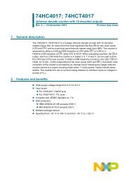
as on board tuners. Fig 1 shows the application diagram of an active splitter with passive<br />
loop-through. It shows that at the moment the power of the recording device (DVD-R,<br />
HDD-R, VCR, DVR) is on, the RF switch is open, so the RF signal travels via the<br />
recording device to the TV tuner. At the moment the power of the recording device is<br />
<strong>com</strong>pletely off, the RF switch closes <strong>and</strong> this ensures that the RF signal is looped<br />
through directly to the TV tuner. Built in <strong>NXP</strong>s own QUBiC4+ Si BiCMOS process these<br />
low noise amplifiers provide programmable gain (-2dB, 5dB <strong>and</strong> 10dB), have integrated<br />
biasing, 75 Ω matching (saving up to 15 external <strong>com</strong>ponents <strong>com</strong>pared to discrete<br />
solutions). These low noise amplifiers are very ESD robust (>2kV HBM <strong>and</strong> >1.5kV<br />
CDM) <strong>com</strong>pared to GaAs solutions. Table 1 gives an overview of this STB LNA family.<br />
In this document, the application diagram, board layout, bill of materials, <strong>and</strong><br />
performance information are given.<br />
DVD-R, HDD-R,<br />
VCR, DVR<br />
Fig 1. Application diagram of an active splitter with passive loop-through<br />
Table 1. Overview product types<br />
Type Number Supply voltage [V] Number of<br />
modes<br />
Description<br />
BGU7031 5.0 1 Fixed Gain 10dB<br />
BGU7032 5.0 2 Gain 10dB<br />
Bypass mode<br />
<strong>AN11209</strong> All information provided in this document is subject to legal disclaimers. © <strong>NXP</strong> B.V. 2012. All rights reserved.<br />
Application note Rev. 1 — 5 October 2012 3 of 82
<strong>NXP</strong> Semiconductors <strong>AN11209</strong><br />
2. Application Circuit<br />
Type Number Supply voltage [V] Number of<br />
modes<br />
<strong>Set</strong>-<strong>Top</strong> <strong>Box</strong> <strong>LNAs</strong> <strong>BGU703X</strong> <strong>and</strong> <strong>BGU704X</strong><br />
Description<br />
BGU7033 5.0 3 Gain 10dB<br />
Gain 5dB<br />
Bypass mode<br />
BGU7041 3.3 1 Fixed Gain 10dB<br />
BGU7042 3.3 2 Gain 10dB<br />
Bypass mode<br />
BGU7044 3.3 1 Fixed Gain 14dB<br />
BGU7045 3.3 2 Gain 14dB<br />
Bypass mode<br />
A universal evaluation board is used to test the RF performance of the whole <strong>NXP</strong> STB<br />
LNA family <strong>BGU703X</strong> <strong>and</strong> <strong>BGU704X</strong>. For all the types, it needs the same input <strong>and</strong><br />
output DC block capacitors, supply decoupling capacitors, <strong>and</strong> RF choke. The difference<br />
between the types is mainly the external resistor used to set an optimum biasing current,<br />
<strong>and</strong> depending on how many modes the type has, the resistor <strong>and</strong> decoupling capacitor<br />
are used for each control line (bypass <strong>and</strong> gain control). The resistor for the control line is<br />
used to protect the control pin of the STB LNA MMIC by limiting the current.<br />
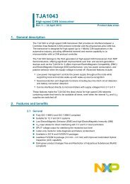
The circuit diagram of the universal evaluation board <strong>and</strong> the board itself are shown in<br />
Fig 2 <strong>and</strong> Fig 3 respectively. Table 2, Table 3, Table 4, Table 5, Table 6, Table 7, <strong>and</strong><br />
Table 8 show the bills of materials for BGU7031, BGU7032, BGU7033, BGU7041,<br />
BGU7042, BGU7044, <strong>and</strong> BGU7045 respectively.<br />
Fig 2. Circuit diagram of universal evaluation board for STB <strong>LNAs</strong> <strong>BGU703X</strong> <strong>and</strong><br />
<strong>BGU704X</strong><br />
<strong>AN11209</strong> All information provided in this document is subject to legal disclaimers. © <strong>NXP</strong> B.V. 2012. All rights reserved.<br />
Application note Rev. 1 — 5 October 2012 4 of 82
<strong>NXP</strong> Semiconductors <strong>AN11209</strong><br />
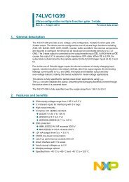
PCB material = FR4.<br />
PCB thickness = 1.6 mm.<br />
PCB size = 30 mm x 30 mm.<br />
εr = 4.5; thickness of copper layer = 35 µm.<br />
<strong>Set</strong>-<strong>Top</strong> <strong>Box</strong> <strong>LNAs</strong> <strong>BGU703X</strong> <strong>and</strong> <strong>BGU704X</strong><br />
Fig 3. Universal evaluation board for STB <strong>LNAs</strong> <strong>BGU703X</strong> <strong>and</strong> <strong>BGU704X</strong><br />
Table 2. Bill of materials BGU7031<br />
Component Value Type Remark<br />
C1 10 nF C0805 DC blocking<br />
C2 10 nF C0805 DC blocking<br />
C3 NC Not connected<br />
C4 NC Not connected<br />
C5 10 nF C0603 RF decoupling<br />
C6 10 µF C1206 RF decoupling<br />
L1 1.5 KΩ L0603 RF Choke: Chip ferrite bead BLM18HE152SN1DF<br />
R1 43 Ω R0603 Bias setting<br />
R2 NC Not connected<br />
R3 NC Not connected<br />
X1 75 Ω F-connector input<br />
X2 75 Ω F-connector output<br />
Table 3. Bill of materials BGU7032<br />
Component Value Type Remark<br />
C1 10 nF C0805 DC blocking<br />
C2 10 nF C0805 DC blocking<br />
<strong>AN11209</strong> All information provided in this document is subject to legal disclaimers. © <strong>NXP</strong> B.V. 2012. All rights reserved.<br />
Application note Rev. 1 — 5 October 2012 5 of 82
<strong>NXP</strong> Semiconductors <strong>AN11209</strong><br />
Component Value Type Remark<br />
C3 10 nF C0603 RF decoupling<br />
C4 NC Not connected<br />
C5 10 nF C0603 RF decoupling<br />
C6 10 µF C1206 RF decoupling<br />
<strong>Set</strong>-<strong>Top</strong> <strong>Box</strong> <strong>LNAs</strong> <strong>BGU703X</strong> <strong>and</strong> <strong>BGU704X</strong><br />
L1 1.5 KΩ L0603 RF Choke: Chip ferrite bead BLM18HE152SN1DF<br />
R1 43 Ω R0603 Bias setting<br />
R2 1.8 KΩ R0603 Current limiting<br />
R3 NC Not connected<br />
X1 75 Ω F-connector input<br />
X2 75 Ω F-connector output<br />
Table 4. Bill of materials BGU7033<br />
Component Value Type Remark<br />
C1 10 nF C0805 DC blocking<br />
C2 10 nF C0805 DC blocking<br />
C3 10 nF C0603 RF decoupling<br />
C4 10 nF C0603 RF decoupling<br />
C5 10 nF C0603 RF decoupling<br />
C6 10 µF C1206 RF decoupling<br />
L1 1.5 KΩ L0603 RF Choke: Chip ferrite bead BLM18HE152SN1DF<br />
R1 43 Ω R0603 Bias setting<br />
R2 1.8 KΩ R0603 Current limiting<br />
R3 1.8 KΩ R0603 Current limiting<br />
X1 75 Ω F-connector input<br />
X2 75 Ω F-connector output<br />
Table 5. Bill of materials BGU7041<br />
Component Value Type Remark<br />
C1 10 nF C0805 DC blocking<br />
C2 10 nF C0805 DC blocking<br />
C3 NC Not connected<br />
C4 NC Not connected<br />
C5 10 nF C0603 RF decoupling<br />
C6 10 µF C1206 RF decoupling<br />
L1 1.5 KΩ L0603 RF Choke: Chip ferrite bead BLM18HE152SN1DF<br />
R1 7.5 Ω R0603 Bias setting<br />
R2 NC Not connected<br />
R3 NC Not connected<br />
X1 75 Ω F-connector input<br />
X2 75 Ω F-connector output<br />
<strong>AN11209</strong> All information provided in this document is subject to legal disclaimers. © <strong>NXP</strong> B.V. 2012. All rights reserved.<br />
Application note Rev. 1 — 5 October 2012 6 of 82
<strong>NXP</strong> Semiconductors <strong>AN11209</strong><br />
Table 6. Bill of materials BGU7042<br />
Component Value Type Remark<br />
C1 10 nF C0805 DC blocking<br />
C2 10 nF C0805 DC blocking<br />
C3 10 nF C0603 RF decoupling<br />
C4 NC Not connected<br />
C5 10 nF C0603 RF decoupling<br />
C6 10 µF C1206 RF decoupling<br />
<strong>Set</strong>-<strong>Top</strong> <strong>Box</strong> <strong>LNAs</strong> <strong>BGU703X</strong> <strong>and</strong> <strong>BGU704X</strong><br />
L1 1.5 KΩ L0603 RF Choke: Chip ferrite bead BLM18HE152SN1DF<br />
R1 7.5 Ω R0603 Bias setting<br />
R2 1.8 KΩ R0603 Current limiting<br />
R3 NC Not connected<br />
X1 75 Ω F-connector input<br />
X2 75 Ω F-connector output<br />
Table 7. Bill of materials BGU7044<br />
Component Value Type Remark<br />
C1 10 nF C0805 DC blocking<br />
C2 10 nF C0805 DC blocking<br />
C3 NC Not connected<br />
C4 NC Not connected<br />
C5 10 nF C0603 RF decoupling<br />
C6 10 µF C1206 RF decoupling<br />
L1 1.5 KΩ L0603 RF Choke: Chip ferrite bead BLM18HE152SN1DF<br />
R1 18 Ω R0603 Bias setting<br />
R2 NC Not connected<br />
R3 NC Not connected<br />
X1 75 Ω F-connector input<br />
X2 75 Ω F-connector output<br />
Table 8. Bill of materials BGU7045<br />
Component Value Type Remark<br />
C1 10 nF C0805 DC blocking<br />
C2 10 nF C0805 DC blocking<br />
C3 10 nF C0603 RF decoupling<br />
C4 NC Not connected<br />
C5 10 nF C0603 RF decoupling<br />
C6 10 µF C1206 RF decoupling<br />
L1 1.5 KΩ L0603 RF Choke: Chip ferrite bead BLM18HE152SN1DF<br />
<strong>AN11209</strong> All information provided in this document is subject to legal disclaimers. © <strong>NXP</strong> B.V. 2012. All rights reserved.<br />
Application note Rev. 1 — 5 October 2012 7 of 82
<strong>NXP</strong> Semiconductors <strong>AN11209</strong><br />
Component Value Type Remark<br />
R1 18 Ω R0603 Bias setting<br />
R2 1.8 KΩ R0603 Current limiting<br />
R3 NC Not connected<br />
X1 75 Ω F-connector input<br />
X2 75 Ω F-connector output<br />
<strong>Set</strong>-<strong>Top</strong> <strong>Box</strong> <strong>LNAs</strong> <strong>BGU703X</strong> <strong>and</strong> <strong>BGU704X</strong><br />
3. RF Performance for Different Bias Currents including Default Current<br />
Because there are trade-offs between bias current, linearity, <strong>and</strong> NF, in this chapter the<br />
RF performance of all STB LNA types is given for different bias currents, including the<br />
default current. The bias current is controlled by the bias resistor <strong>and</strong> Table 9 shows an<br />
overview of the resistor values for different bias currents in gain mode of different types.<br />
Table 9. Overview resistor values for different bias currents in gain mode of different<br />
types<br />
Type Rbias [Ω]<br />
ICC≈35mA ICC≈39mA ICC≈43mA ICC≈46mA<br />
BGU7031/2/3 N/A N/A 43 (default) 39<br />
BGU7041/2 7.5 (default) 5.6 N/A N/A<br />
BGU7044/5 18 (default) N/A 10 N/A<br />
3.1 RF Test <strong>Set</strong>up<br />
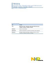
3.1.1 IM2, <strong>and</strong> IM3 measurement setup<br />
For the IM2, <strong>and</strong> IM3 measurements in this report, the equipment list in Table 10 has<br />
been used <strong>and</strong> Fig 4 shows the test setup diagram.<br />
Table 10. Equipment list for P1dB, IM2, <strong>and</strong> IM3 measurements<br />
Instrument Manufacturer Type<br />
(1x) 4- Port Vector Network<br />
Analyzer 10MHz – 24GHz<br />
Rohde & Schwarz ZVA24<br />
(2x) Dual DC Power Supply TTi QL355TP<br />
(1x) USB Powermeter Rohde & Schwarz NRP – Z21<br />
(1x) Multimeter Keithley 2000<br />
(1x) Power Combiner Agilent 11667B<br />
(2x) Impedance Matching<br />
Transformer 75Ω/50Ω, Nconnectors<br />
Ma<strong>com</strong> TPX-75-4<br />
<strong>AN11209</strong> All information provided in this document is subject to legal disclaimers. © <strong>NXP</strong> B.V. 2012. All rights reserved.<br />
Application note Rev. 1 — 5 October 2012 8 of 82
<strong>NXP</strong> Semiconductors <strong>AN11209</strong><br />
<strong>Set</strong>-<strong>Top</strong> <strong>Box</strong> <strong>LNAs</strong> <strong>BGU703X</strong> <strong>and</strong> <strong>BGU704X</strong><br />
Instrument Manufacturer Type<br />
3x Cables from ZVA Rohde & Schwarz Test cables PC2.9/PC3.5<br />
1x Cable to input Suhner Sucoflex104E, appr.50cm<br />
1x Cable from output Suhner Sucoflex104PE, appr.20cm<br />
Additional connectors, cables<br />
<strong>and</strong> adapters as in drawing<br />
SMA to N→Tpx-50-75ohm→N to F<br />
Bomar, Suhner, Radiall n.a.<br />
Fig 4. Test setup diagram for IM2, <strong>and</strong> IM3 measurements<br />
F to N→Tpx-75-50ohm→N to SMA<br />
3.1.2 NF measurement setup<br />
For the NF measurement in this report, the equipment list in Table 11 has been used <strong>and</strong><br />
Fig 5 shows the test setup diagram.<br />
Table 11. Equipment list for NF measurement<br />
Description Manufacturer Number<br />
Noise Figure Analyzer 10MHz – 1600MHz Agilent 8970A<br />
Noise source 15dB / N(m) / 50Ω Agilent 346B<br />
DC Power-supply TTi QL564P<br />
Multimeter Agilent 34401A<br />
Impedance adapters 5.7dB Loss Pad (N-f)<br />
50Ω / (N-m) 75Ω<br />
Agilent 11852B<br />
Connector adapters (N-f) 75Ω / (F-m) 75Ω Bomar<br />
<strong>AN11209</strong> All information provided in this document is subject to legal disclaimers. © <strong>NXP</strong> B.V. 2012. All rights reserved.<br />
Application note Rev. 1 — 5 October 2012 9 of 82
<strong>NXP</strong> Semiconductors <strong>AN11209</strong><br />
PSU<br />
Noise source<br />
50Ω / N-m<br />
<strong>Set</strong>-<strong>Top</strong> <strong>Box</strong> <strong>LNAs</strong> <strong>BGU703X</strong> <strong>and</strong> <strong>BGU704X</strong><br />
Noise Figure Analyzer (NFA) Agilent 8970A<br />
DMM<br />
50 N-f<br />
Imp.<br />
Adapt.<br />
75 N-m<br />
28VDC<br />
pulsed<br />
Conn.adapt<br />
N-f<br />
75Ω<br />
Noise test setup<br />
Fig 5. Test setup diagram for NF measurement<br />
3.2 2 nd Order Intermodulation (IM2)<br />
For IM2 measurement ZVA S-par. system calibration is not needed since it is a pure <strong>and</strong><br />
relative power amplitude measurement. Thus only manual Power calibration is required.<br />
For this measurement, two tones are used separated by 200MHz or 6MHz, depending on<br />
the specification. Via a broadb<strong>and</strong> power <strong>com</strong>biner <strong>and</strong> 50Ω to 75Ω impedance<br />
transformers the two tones with equal amplitude are fed into the DUT. The measurement<br />
has been done with f1=200MHz or f1=97.25MHz, depending on the specification, <strong>and</strong> an<br />
input power sweep from -20dBm to 5dBm per tone is applied. The pre-defined losses of<br />
the 50Ω to 75Ω impedance transformers etc. are <strong>com</strong>pensated afterwards using output<br />
data processing. With Power calibration the reference plane is the SMA connector at the<br />
50Ω input cable just before the SMA to N adapter that is connected to the input<br />
transformer. For IM2, only f1+f2 product has been measured.<br />
<strong>AN11209</strong> All information provided in this document is subject to legal disclaimers. © <strong>NXP</strong> B.V. 2012. All rights reserved.<br />
Application note Rev. 1 — 5 October 2012 10 of 82<br />
Fm<br />
NFA<br />
Test fixture<br />
50Ω input N-f<br />
F-f<br />
Test<br />
pcb F-f<br />
Fm<br />
N-f<br />
75Ω<br />
75 N-m<br />
Imp.<br />
Adapt.<br />
50 N-f<br />
PC<br />
HQ 50Ω cable N-m / N-m<br />
Conn.adapt<br />
With calibration connect NS via an N-f/N-f adapter via the HQ 50Ω cable to the NFA
<strong>NXP</strong> Semiconductors <strong>AN11209</strong><br />
<strong>Set</strong>-<strong>Top</strong> <strong>Box</strong> <strong>LNAs</strong> <strong>BGU703X</strong> <strong>and</strong> <strong>BGU704X</strong><br />
The IM2 measurement results for different bias currents of <strong>BGU703X</strong> (5.0V devices) <strong>and</strong><br />
<strong>BGU704X</strong> (3.3V devices) are given in chapter 3.2.1 with f1=200MHz <strong>and</strong> tone spacing of<br />
200MHz <strong>and</strong> chapter 3.2.2 with f1=97.25MHz <strong>and</strong> tone spacing of 6MHz.<br />
3.2.1 IM2 with f1=200MHz, f2=400MHz, fIM2=600MHz; Pin per tone swept from -<br />
20dBm to 5dBm<br />
Table 12 shows an overview of IIP2 with f1=200MHz, f2=400MHz, fIM2=600MHz; <strong>and</strong> Pin<br />
=-15dBm per tone for BGU703x (5.0V devices) <strong>and</strong> BGU704x (3.3V devices) in different<br />
modes.<br />
Table 12. Overview of IIP2 with f1=200MHz, f2=400MHz, fIM2=600MHz; <strong>and</strong> Pin =-15dBm per<br />
tone for BGU703x <strong>and</strong> BGU704x in different modes<br />
3.2.1.1 BGU7031: IM2 with f1=200MHz, f2=400MHz, fIM2=600MHz; Pin per tone swept from -<br />
20dBm to 5dBm<br />
Fig 6 to Fig 7 show 1 st <strong>and</strong> 2 nd order response of BGU7031 in 10dB gain mode with<br />
f1=200MHz, f2=400MHz, fIM2=600MHz; <strong>and</strong> Pin per tone swept from -20dBm to 5dBm.<br />
(1) 1 st order<br />
(2) 2 nd order<br />
(3) 1 st order extrapolation<br />
(4) 2 nd order extrapolation<br />
Fig 6. IM2 of BGU7031 in 10dB gain mode with Icc=46mA (Rbias=39Ω); f1=200MHz,<br />
f2=400MHz, fIM2=600MHz; Pin per tone swept from -20dBm to 5dBm<br />
<strong>AN11209</strong> All information provided in this document is subject to legal disclaimers. © <strong>NXP</strong> B.V. 2012. All rights reserved.<br />
Application note Rev. 1 — 5 October 2012 11 of 82
<strong>NXP</strong> Semiconductors <strong>AN11209</strong><br />
(1) 1 st order<br />
(2) 2 nd order<br />
(3) 1 st order extrapolation<br />
(4) 2 nd order extrapolation<br />
<strong>Set</strong>-<strong>Top</strong> <strong>Box</strong> <strong>LNAs</strong> <strong>BGU703X</strong> <strong>and</strong> <strong>BGU704X</strong><br />
Fig 7. IM2 of BGU7031 in 10dB gain mode with Icc=43mA (Rbias=43Ω); f1=200MHz,<br />
f2=400MHz, fIM2=600MHz; Pin per tone swept from -20dBm to 5dBm<br />
3.2.1.2 BGU7032: IM2 with f1=200MHz, f2=400MHz, fIM2=600MHz; Pin per tone swept from -<br />
20dBm to 5dBm<br />
Fig 8 to Fig 11 show 1 st <strong>and</strong> 2 nd order response of BGU7032 in 10dB gain <strong>and</strong> bypass<br />
modes with f1=200MHz, f2=400MHz, fIM2=600MHz; <strong>and</strong> Pin per tone swept from -20dBm<br />
to 5dBm.<br />
(1) 1 st order<br />
(2) 2 nd order<br />
(3) 1 st order extrapolation<br />
(4) 2 nd order extrapolation<br />
Fig 8. IM2 of BGU7032 in 10dB gain mode with Icc=46mA (Rbias=39Ω); f1=200MHz,<br />
f2=400MHz, fIM2=600MHz; Pin per tone swept from -20dBm to 5dBm<br />
<strong>AN11209</strong> All information provided in this document is subject to legal disclaimers. © <strong>NXP</strong> B.V. 2012. All rights reserved.<br />
Application note Rev. 1 — 5 October 2012 12 of 82
<strong>NXP</strong> Semiconductors <strong>AN11209</strong><br />
(1) 1 st order<br />
(2) 2 nd order<br />
(3) 1 st order extrapolation<br />
(4) 2 nd order extrapolation<br />
<strong>Set</strong>-<strong>Top</strong> <strong>Box</strong> <strong>LNAs</strong> <strong>BGU703X</strong> <strong>and</strong> <strong>BGU704X</strong><br />
Fig 9. IM2 of BGU7032 in Bypass mode with Icc=4mA; Rbias=39Ω; f1=200MHz,<br />
f2=400MHz, fIM2=600MHz; Pin per tone swept from -20dBm to 5dBm<br />
(1) 1 st order<br />
(2) 2 nd order<br />
(3) 1 st order extrapolation<br />
(4) 2 nd order extrapolation<br />
Fig 10. IM2 of BGU7032 in 10dB gain mode with Icc=43mA (Rbias=43Ω); f1=200MHz,<br />
f2=400MHz, fIM2=600MHz; Pin per tone swept from -20dBm to 5dBm<br />
<strong>AN11209</strong> All information provided in this document is subject to legal disclaimers. © <strong>NXP</strong> B.V. 2012. All rights reserved.<br />
Application note Rev. 1 — 5 October 2012 13 of 82
<strong>NXP</strong> Semiconductors <strong>AN11209</strong><br />
(1) 1 st order<br />
(2) 2 nd order<br />
(3) 1 st order extrapolation<br />
(4) 2 nd order extrapolation<br />
<strong>Set</strong>-<strong>Top</strong> <strong>Box</strong> <strong>LNAs</strong> <strong>BGU703X</strong> <strong>and</strong> <strong>BGU704X</strong><br />
Fig 11. IM2 of BGU7032 in Bypass mode with Icc=4mA; Rbias=43Ω; f1=200MHz,<br />
f2=400MHz, fIM2=600MHz; Pin per tone swept from -20dBm to 5dBm<br />
3.2.1.3 BGU7033: IM2 with f1=200MHz, f2=400MHz, fIM2=600MHz; Pin per tone swept from -<br />
20dBm to 5dBm<br />
Fig 12 to Fig 17 show 1 st <strong>and</strong> 2 nd order response of BGU7033 in 10dB gain, 5dB gain,<br />
<strong>and</strong> bypass modes with f1=200MHz, f2=400MHz, fIM2=600MHz; <strong>and</strong> Pin per tone swept<br />
from -20dBm to 5dBm.<br />
(1) 1 st order<br />
(2) 2 nd order<br />
(3) 1 st order extrapolation<br />
(4) 2 nd order extrapolation<br />
Fig 12. IM2 of BGU7033 in 10dB gain mode with Icc=46mA (Rbias=39Ω); f1=200MHz,<br />
f2=400MHz, fIM2=600MHz; Pin per tone swept from -20dBm to 5dBm<br />
<strong>AN11209</strong> All information provided in this document is subject to legal disclaimers. © <strong>NXP</strong> B.V. 2012. All rights reserved.<br />
Application note Rev. 1 — 5 October 2012 14 of 82
<strong>NXP</strong> Semiconductors <strong>AN11209</strong><br />
(1) 1 st order<br />
(2) 2 nd order<br />
(3) 1 st order extrapolation<br />
(4) 2 nd order extrapolation<br />
<strong>Set</strong>-<strong>Top</strong> <strong>Box</strong> <strong>LNAs</strong> <strong>BGU703X</strong> <strong>and</strong> <strong>BGU704X</strong><br />
Fig 13. IM2 of BGU7033 in 5dB gain mode with Icc=46mA (Rbias=39Ω); f1=200MHz,<br />
f2=400MHz, fIM2=600MHz; Pin per tone swept from -20dBm to 5dBm<br />
(1) 1 st order<br />
(2) 2 nd order<br />
(3) 1 st order extrapolation<br />
(4) 2 nd order extrapolation<br />
Fig 14. IM2 of BGU7033 in Bypass mode with Icc=4mA; Rbias=39Ω; f1=200MHz,<br />
f2=400MHz, fIM2=600MHz; Pin per tone swept from -20dBm to 5dBm<br />
<strong>AN11209</strong> All information provided in this document is subject to legal disclaimers. © <strong>NXP</strong> B.V. 2012. All rights reserved.<br />
Application note Rev. 1 — 5 October 2012 15 of 82
<strong>NXP</strong> Semiconductors <strong>AN11209</strong><br />
(1) 1 st order<br />
(2) 2 nd order<br />
(3) 1 st order extrapolation<br />
(4) 2 nd order extrapolation<br />
<strong>Set</strong>-<strong>Top</strong> <strong>Box</strong> <strong>LNAs</strong> <strong>BGU703X</strong> <strong>and</strong> <strong>BGU704X</strong><br />
Fig 15. IM2 of BGU7033 in 10dB gain mode with Icc=43mA (Rbias=43Ω); f1=200MHz,<br />
f2=400MHz, fIM2=600MHz; Pin per tone swept from -20dBm to 5dBm<br />
(1) 1 st order<br />
(2) 2 nd order<br />
(3) 1 st order extrapolation<br />
(4) 2 nd order extrapolation<br />
Fig 16. IM2 of BGU7033 in 5dB gain mode with Icc=43mA (Rbias=43Ω); f1=200MHz,<br />
f2=400MHz, fIM2=600MHz; Pin per tone swept from -20dBm to 5dBm<br />
<strong>AN11209</strong> All information provided in this document is subject to legal disclaimers. © <strong>NXP</strong> B.V. 2012. All rights reserved.<br />
Application note Rev. 1 — 5 October 2012 16 of 82
<strong>NXP</strong> Semiconductors <strong>AN11209</strong><br />
(1) 1 st order<br />
(2) 2 nd order<br />
(3) 1 st order extrapolation<br />
(4) 2 nd order extrapolation<br />
<strong>Set</strong>-<strong>Top</strong> <strong>Box</strong> <strong>LNAs</strong> <strong>BGU703X</strong> <strong>and</strong> <strong>BGU704X</strong><br />
Fig 17. IM2 of BGU7033 in Bypass mode with Icc=4mA; Rbias=43Ω; f1=200MHz,<br />
f2=400MHz, fIM2=600MHz; Pin per tone swept from -20dBm to 5dBm<br />
3.2.1.4 BGU7041: IM2 with f1=200MHz, f2=400MHz, fIM2=600MHz; Pin per tone swept from -<br />
20dBm to 5dBm<br />
Fig 18 to Fig 19 show 1 st <strong>and</strong> 2 nd order response of BGU7041 in 10dB gain mode with<br />
f1=200MHz, f2=400MHz, fIM2=600MHz; <strong>and</strong> Pin per tone swept from -20dBm to 5dBm.<br />
(1) 1 st order<br />
(2) 2 nd order<br />
(3) 1 st order extrapolation<br />
(4) 2 nd order extrapolation<br />
Fig 18. IM2 of BGU7041 in 10dB gain mode with Icc=39mA (Rbias=5.6Ω); f1=200MHz,<br />
f2=400MHz, fIM2=600MHz; Pin per tone swept from -20dBm to 5dBm<br />
<strong>AN11209</strong> All information provided in this document is subject to legal disclaimers. © <strong>NXP</strong> B.V. 2012. All rights reserved.<br />
Application note Rev. 1 — 5 October 2012 17 of 82
<strong>NXP</strong> Semiconductors <strong>AN11209</strong><br />
(1) 1 st order<br />
(2) 2 nd order<br />
(3) 1 st order extrapolation<br />
(4) 2 nd order extrapolation<br />
<strong>Set</strong>-<strong>Top</strong> <strong>Box</strong> <strong>LNAs</strong> <strong>BGU703X</strong> <strong>and</strong> <strong>BGU704X</strong><br />
Fig 19. IM2 of BGU7041 in 10dB gain mode with Icc=35mA (Rbias=7.5Ω); f1=200MHz,<br />
f2=400MHz, fIM2=600MHz; Pin per tone swept from -20dBm to 5dBm<br />
3.2.1.5 BGU7042: IM2 with f1=200MHz, f2=400MHz, fIM2=600MHz; Pin per tone swept from -<br />
20dBm to 5dBm<br />
Fig 20 to Fig 23 show 1 st <strong>and</strong> 2 nd order response of BGU7042 in 10dB gain <strong>and</strong> bypass<br />
modes with f1=200MHz, f2=400MHz, fIM2=600MHz; <strong>and</strong> Pin per tone swept from -20dBm<br />
to 5dBm.<br />
(1) 1 st order<br />
(2) 2 nd order<br />
(3) 1 st order extrapolation<br />
(4) 2 nd order extrapolation<br />
Fig 20. IM2 of BGU7042 in 10dB gain mode with Icc=39mA (Rbias=5.6Ω); f1=200MHz,<br />
f2=400MHz, fIM2=600MHz; Pin per tone swept from -20dBm to 5dBm<br />
<strong>AN11209</strong> All information provided in this document is subject to legal disclaimers. © <strong>NXP</strong> B.V. 2012. All rights reserved.<br />
Application note Rev. 1 — 5 October 2012 18 of 82
<strong>NXP</strong> Semiconductors <strong>AN11209</strong><br />
(1) 1 st order<br />
(2) 2 nd order<br />
(3) 1 st order extrapolation<br />
(4) 2 nd order extrapolation<br />
<strong>Set</strong>-<strong>Top</strong> <strong>Box</strong> <strong>LNAs</strong> <strong>BGU703X</strong> <strong>and</strong> <strong>BGU704X</strong><br />
Fig 21. IM2 of BGU7042 in Bypass mode with Icc=3mA; Rbias=5.6Ω; f1=200MHz,<br />
f2=400MHz, fIM2=600MHz; Pin per tone swept from -20dBm to 5dBm<br />
(1) 1 st order<br />
(2) 2 nd order<br />
(3) 1 st order extrapolation<br />
(4) 2 nd order extrapolation<br />
Fig 22. IM2 of BGU7042 in 10dB gain mode with Icc=35mA (Rbias=7.5Ω); f1=200MHz,<br />
f2=400MHz, fIM2=600MHz; Pin per tone swept from -20dBm to 5dBm<br />
<strong>AN11209</strong> All information provided in this document is subject to legal disclaimers. © <strong>NXP</strong> B.V. 2012. All rights reserved.<br />
Application note Rev. 1 — 5 October 2012 19 of 82
<strong>NXP</strong> Semiconductors <strong>AN11209</strong><br />
(1) 1 st order<br />
(2) 2 nd order<br />
(3) 1 st order extrapolation<br />
(4) 2 nd order extrapolation<br />
<strong>Set</strong>-<strong>Top</strong> <strong>Box</strong> <strong>LNAs</strong> <strong>BGU703X</strong> <strong>and</strong> <strong>BGU704X</strong><br />
Fig 23. IM2 of BGU7042 in Bypass mode with Icc=3mA; Rbias=7.5Ω; f1=200MHz,<br />
f2=400MHz, fIM2=600MHz; Pin per tone swept from -20dBm to 5dBm<br />
3.2.1.6 BGU7044: IM2 with f1=200MHz, f2=400MHz, fIM2=600MHz; Pin per tone swept from -<br />
20dBm to 5dBm<br />
Fig 24 to Fig 25 show 1 st <strong>and</strong> 2 nd order response of BGU7044 in 14dB gain mode with<br />
f1=200MHz, f2=400MHz, fIM2=600MHz; <strong>and</strong> Pin per tone swept from -20dBm to 5dBm.<br />
(1) 1 st order<br />
(2) 2 nd order<br />
(3) 1 st order extrapolation<br />
(4) 2 nd order extrapolation<br />
Fig 24. IM2 of BGU7044 in 14dB gain mode with Icc=43mA (Rbias=10Ω); f1=200MHz,<br />
f2=400MHz, fIM2=600MHz; Pin per tone swept from -20dBm to 5dBm<br />
<strong>AN11209</strong> All information provided in this document is subject to legal disclaimers. © <strong>NXP</strong> B.V. 2012. All rights reserved.<br />
Application note Rev. 1 — 5 October 2012 20 of 82
<strong>NXP</strong> Semiconductors <strong>AN11209</strong><br />
(1) 1 st order<br />
(2) 2 nd order<br />
(3) 1 st order extrapolation<br />
(4) 2 nd order extrapolation<br />
<strong>Set</strong>-<strong>Top</strong> <strong>Box</strong> <strong>LNAs</strong> <strong>BGU703X</strong> <strong>and</strong> <strong>BGU704X</strong><br />
Fig 25. IM2 of BGU7044 in 14dB gain mode with Icc=35mA (Rbias=18Ω); f1=200MHz,<br />
f2=400MHz, fIM2=600MHz; Pin per tone swept from -20dBm to 5dBm<br />
3.2.1.7 BGU7045: IM2 with f1=200MHz, f2=400MHz, fIM2=600MHz; Pin per tone swept from -<br />
20dBm to 5dBm<br />
Fig 26 to Fig 29 show 1 st <strong>and</strong> 2 nd order response of BGU7044 in 14dB gain <strong>and</strong> bypass<br />
modes with f1=200MHz, f2=400MHz, fIM2=600MHz; <strong>and</strong> Pin per tone swept from -20dBm<br />
to 5dBm.<br />
(1) 1 st order<br />
(2) 2 nd order<br />
(3) 1 st order extrapolation<br />
(4) 2 nd order extrapolation<br />
Fig 26. IM2 of BGU7045 in 14dB gain mode with Icc=43mA (Rbias=10Ω); f1=200MHz,<br />
f2=400MHz, fIM2=600MHz; Pin per tone swept from -20dBm to 5dBm<br />
<strong>AN11209</strong> All information provided in this document is subject to legal disclaimers. © <strong>NXP</strong> B.V. 2012. All rights reserved.<br />
Application note Rev. 1 — 5 October 2012 21 of 82
<strong>NXP</strong> Semiconductors <strong>AN11209</strong><br />
(1) 1 st order<br />
(2) 2 nd order<br />
(3) 1 st order extrapolation<br />
(4) 2 nd order extrapolation<br />
<strong>Set</strong>-<strong>Top</strong> <strong>Box</strong> <strong>LNAs</strong> <strong>BGU703X</strong> <strong>and</strong> <strong>BGU704X</strong><br />
Fig 27. IM2 of BGU7045 in Bypass mode with Icc=3mA; Rbias=10Ω; f1=200MHz,<br />
f2=400MHz, fIM2=600MHz; Pin per tone swept from -20dBm to 5dBm<br />
(1) 1 st order<br />
(2) 2 nd order<br />
(3) 1 st order extrapolation<br />
(4) 2 nd order extrapolation<br />
Fig 28. IM2 of BGU7045 in 14dB gain mode with Icc=35mA (Rbias=18Ω); f1=200MHz,<br />
f2=400MHz, fIM2=600MHz; Pin per tone swept from -20dBm to 5dBm<br />
<strong>AN11209</strong> All information provided in this document is subject to legal disclaimers. © <strong>NXP</strong> B.V. 2012. All rights reserved.<br />
Application note Rev. 1 — 5 October 2012 22 of 82
<strong>NXP</strong> Semiconductors <strong>AN11209</strong><br />
(1) 1 st order<br />
(2) 2 nd order<br />
(3) 1 st order extrapolation<br />
(4) 2 nd order extrapolation<br />
<strong>Set</strong>-<strong>Top</strong> <strong>Box</strong> <strong>LNAs</strong> <strong>BGU703X</strong> <strong>and</strong> <strong>BGU704X</strong><br />
Fig 29. IM2 of BGU7045 in Bypass mode with Icc=3mA; Rbias=18Ω; f1=200MHz,<br />
f2=400MHz, fIM2=600MHz; Pin per tone swept from -20dBm to 5dBm<br />
3.2.2 IM2 with f1=97.25MHz, f2=103.25MHz, fIM2=200.50MHz; Pin per tone swept<br />
from -20dBm to 5dBm<br />
Table 13 shows an overview of IIP2 with f1=97.25MHz, f2=103.25MHz, fIM2=200.50MHz;<br />
<strong>and</strong> Pin =-20dBm per tone for BGU703x (5.0V devices) <strong>and</strong> BGU704x (3.3V devices) in<br />
different modes.<br />
Table 13. Overview of IIP2 with f1=97.25MHz, f2=103.25MHz, fIM2=200.50MHz; <strong>and</strong> Pin = -<br />
20dBm per tone for BGU703x <strong>and</strong> BGU704x in different modes<br />
3.2.2.1 BGU7031: IM2 with f1=97.25MHz, f2=103.25MHz, fIM2=200.50MHz; Pin per tone swept<br />
from -20dBm to 5dBm<br />
Fig 30 to Fig 31 show 1 st <strong>and</strong> 2 nd order response of BGU7031 in 10dB gain mode with<br />
f1=97.25MHz, f2=103.25MHz, fIM2=200.50MHz; Pin per tone swept from -20dBm to 5dBm.<br />
<strong>AN11209</strong> All information provided in this document is subject to legal disclaimers. © <strong>NXP</strong> B.V. 2012. All rights reserved.<br />
Application note Rev. 1 — 5 October 2012 23 of 82
<strong>NXP</strong> Semiconductors <strong>AN11209</strong><br />
(1) 1 st order<br />
(2) 2 nd order<br />
(3) 1 st order extrapolation<br />
(4) 2 nd order extrapolation<br />
<strong>Set</strong>-<strong>Top</strong> <strong>Box</strong> <strong>LNAs</strong> <strong>BGU703X</strong> <strong>and</strong> <strong>BGU704X</strong><br />
Fig 30. IM2 of BGU7031 in 10dB gain mode with Icc=46mA (Rbias=39Ω); f1=97.25MHz,<br />
f2=103.25MHz, fIM2=200.50MHz; Pin per tone swept from -20dBm to 5dBm<br />
(1) 1 st order<br />
(2) 2 nd order<br />
(3) 1 st order extrapolation<br />
(4) 2 nd order extrapolation<br />
Fig 31. IM2 of BGU7031 in 10dB gain mode with Icc=43mA (Rbias=43Ω); f1=97.25MHz,<br />
f2=103.25MHz, fIM2=200.50MHz; Pin per tone swept from -20dBm to 5dBm<br />
<strong>AN11209</strong> All information provided in this document is subject to legal disclaimers. © <strong>NXP</strong> B.V. 2012. All rights reserved.<br />
Application note Rev. 1 — 5 October 2012 24 of 82
<strong>NXP</strong> Semiconductors <strong>AN11209</strong><br />
<strong>Set</strong>-<strong>Top</strong> <strong>Box</strong> <strong>LNAs</strong> <strong>BGU703X</strong> <strong>and</strong> <strong>BGU704X</strong><br />
3.2.2.2 BGU7032: IM2 with f1=97.25MHz, f2=103.25MHz, fIM2=200.50MHz; Pin per tone swept<br />
from -20dBm to 5dBm<br />
Fig 32 to Fig 35 show 1 st <strong>and</strong> 2 nd order response of BGU7032 in 10dB gain <strong>and</strong> bypass<br />
modes with f1=97.25MHz, f2=103.25MHz, fIM2=200.50MHz; Pin per tone swept from -<br />
20dBm to 5dBm.<br />
(1) 1 st order<br />
(2) 2 nd order<br />
(3) 1 st order extrapolation<br />
(4) 2 nd order extrapolation<br />
Fig 32. IM2 of BGU7032 in 10dB gain mode with Icc=46mA (Rbias=39Ω); f1=97.25MHz,<br />
f2=103.25MHz, fIM2=200.50MHz; Pin per tone swept from -20dBm to 5dBm<br />
(1) 1 st order<br />
(2) 2 nd order<br />
(3) 1 st order extrapolation<br />
(4) 2 nd order extrapolation<br />
Fig 33. IM2 of BGU7032 in Bypass mode with Icc=4mA; Rbias=39Ω; f1=97.25MHz,<br />
f2=103.25MHz, fIM2=200.50MHz; Pin per tone swept from -20dBm to 5dBm<br />
<strong>AN11209</strong> All information provided in this document is subject to legal disclaimers. © <strong>NXP</strong> B.V. 2012. All rights reserved.<br />
Application note Rev. 1 — 5 October 2012 25 of 82
<strong>NXP</strong> Semiconductors <strong>AN11209</strong><br />
(1) 1 st order<br />
(2) 2 nd order<br />
(3) 1 st order extrapolation<br />
(4) 2 nd order extrapolation<br />
<strong>Set</strong>-<strong>Top</strong> <strong>Box</strong> <strong>LNAs</strong> <strong>BGU703X</strong> <strong>and</strong> <strong>BGU704X</strong><br />
Fig 34. IM2 of BGU7032 in 10dB gain mode with Icc=43mA (Rbias=43Ω); f1=97.25MHz,<br />
f2=103.25MHz, fIM2=200.50MHz; Pin per tone swept from -20dBm to 5dBm<br />
(1) 1 st order<br />
(2) 2 nd order<br />
(3) 1 st order extrapolation<br />
(4) 2 nd order extrapolation<br />
Fig 35. IM2 of BGU7032 in Bypass mode with Icc=4mA; Rbias=43Ω; f1=97.25MHz,<br />
f2=103.25MHz, fIM2=200.50MHz; Pin per tone swept from -20dBm to 5dBm<br />
<strong>AN11209</strong> All information provided in this document is subject to legal disclaimers. © <strong>NXP</strong> B.V. 2012. All rights reserved.<br />
Application note Rev. 1 — 5 October 2012 26 of 82
<strong>NXP</strong> Semiconductors <strong>AN11209</strong><br />
<strong>Set</strong>-<strong>Top</strong> <strong>Box</strong> <strong>LNAs</strong> <strong>BGU703X</strong> <strong>and</strong> <strong>BGU704X</strong><br />
3.2.2.3 BGU7033: IM2 with f1=97.25MHz, f2=103.25MHz, fIM2=200.50MHz; Pin per tone swept<br />
from -20dBm to 5dBm<br />
Fig 36 to Fig 41 show 1 st <strong>and</strong> 2 nd order response of BGU7033 in 10dB gain, 5dB gain,<br />
<strong>and</strong> bypass modes with f1=97.25MHz, f2=103.25MHz, fIM2=200.50MHz; Pin per tone<br />
swept from -20dBm to 5dBm.<br />
(1) 1 st order<br />
(2) 2 nd order<br />
(3) 1 st order extrapolation<br />
(4) 2 nd order extrapolation<br />
Fig 36. IM2 of BGU7033 in 10dB gain mode with Icc=46mA (Rbias=39Ω); f1=97.25MHz,<br />
f2=103.25MHz, fIM2=200.50MHz; Pin per tone swept from -20dBm to 5dBm<br />
(1) 1 st order<br />
(2) 2 nd order<br />
(3) 1 st order extrapolation<br />
(4) 2 nd order extrapolation<br />
Fig 37. IM2 of BGU7033 in 5dB gain mode with Icc=46mA (Rbias=39Ω); f1=97.25MHz,<br />
f2=103.25MHz, fIM2=200.50MHz; Pin per tone swept from -20dBm to 5dBm<br />
<strong>AN11209</strong> All information provided in this document is subject to legal disclaimers. © <strong>NXP</strong> B.V. 2012. All rights reserved.<br />
Application note Rev. 1 — 5 October 2012 27 of 82
<strong>NXP</strong> Semiconductors <strong>AN11209</strong><br />
(1) 1 st order<br />
(2) 2 nd order<br />
(3) 1 st order extrapolation<br />
(4) 2 nd order extrapolation<br />
<strong>Set</strong>-<strong>Top</strong> <strong>Box</strong> <strong>LNAs</strong> <strong>BGU703X</strong> <strong>and</strong> <strong>BGU704X</strong><br />
Fig 38. IM2 of BGU7033 in Bypass mode with Icc=4mA; Rbias=39Ω; f1=97.25MHz,<br />
f2=103.25MHz, fIM2=200.50MHz; Pin per tone swept from -20dBm to 5dBm<br />
(1) 1 st order<br />
(2) 2 nd order<br />
(3) 1 st order extrapolation<br />
(4) 2 nd order extrapolation<br />
Fig 39. IM2 of BGU7033 in 10dB gain mode with Icc=43mA (Rbias=43Ω); f1=97.25MHz,<br />
f2=103.25MHz, fIM2=200.50MHz; Pin per tone swept from -20dBm to 5dBm<br />
<strong>AN11209</strong> All information provided in this document is subject to legal disclaimers. © <strong>NXP</strong> B.V. 2012. All rights reserved.<br />
Application note Rev. 1 — 5 October 2012 28 of 82
<strong>NXP</strong> Semiconductors <strong>AN11209</strong><br />
(1) 1 st order<br />
(2) 2 nd order<br />
(3) 1 st order extrapolation<br />
(4) 2 nd order extrapolation<br />
<strong>Set</strong>-<strong>Top</strong> <strong>Box</strong> <strong>LNAs</strong> <strong>BGU703X</strong> <strong>and</strong> <strong>BGU704X</strong><br />
Fig 40. IM2 of BGU7033 in 5dB gain mode with Icc=43mA (Rbias=43Ω); f1=97.25MHz,<br />
f2=103.25MHz, fIM2=200.50MHz; Pin per tone swept from -20dBm to 5dBm<br />
(1) 1 st order<br />
(2) 2 nd order<br />
(3) 1 st order extrapolation<br />
(4) 2 nd order extrapolation<br />
Fig 41. IM2 of BGU7033 in Bypass mode with Icc=4mA; Rbias=43Ω; f1=97.25MHz,<br />
f2=103.25MHz, fIM2=200.50MHz; Pin per tone swept from -20dBm to 5dBm<br />
<strong>AN11209</strong> All information provided in this document is subject to legal disclaimers. © <strong>NXP</strong> B.V. 2012. All rights reserved.<br />
Application note Rev. 1 — 5 October 2012 29 of 82
<strong>NXP</strong> Semiconductors <strong>AN11209</strong><br />
<strong>Set</strong>-<strong>Top</strong> <strong>Box</strong> <strong>LNAs</strong> <strong>BGU703X</strong> <strong>and</strong> <strong>BGU704X</strong><br />
3.2.2.4 BGU7041: IM2 with f1=97.25MHz, f2=103.25MHz, fIM2=200.50MHz; Pin per tone swept<br />
from -20dBm to 5dBm<br />
Fig 42 to Fig 43 show 1 st <strong>and</strong> 2 nd order response of BGU7041 in 10dB gain mode with<br />
f1=97.25MHz, f2=103.25MHz, fIM2=200.50MHz; Pin per tone swept from -20dBm to 5dBm.<br />
(1) 1 st order<br />
(2) 2 nd order<br />
(3) 1 st order extrapolation<br />
(4) 2 nd order extrapolation<br />
Fig 42. IM2 of BGU7041 in 10dB gain mode with Icc=39mA (Rbias=5.6Ω); f1=97.25MHz,<br />
f2=103.25MHz, fIM2=200.50MHz; Pin per tone swept from -20dBm to 5dBm<br />
(1) 1 st order<br />
(2) 2 nd order<br />
(3) 1 st order extrapolation<br />
(4) 2 nd order extrapolation<br />
Fig 43. IM2 of BGU7041 in 10dB gain mode with Icc=35mA (Rbias=7.5Ω); f1=97.25MHz,<br />
f2=103.25MHz, fIM2=200.50MHz; Pin per tone swept from -20dBm to 5dBm<br />
<strong>AN11209</strong> All information provided in this document is subject to legal disclaimers. © <strong>NXP</strong> B.V. 2012. All rights reserved.<br />
Application note Rev. 1 — 5 October 2012 30 of 82
<strong>NXP</strong> Semiconductors <strong>AN11209</strong><br />
<strong>Set</strong>-<strong>Top</strong> <strong>Box</strong> <strong>LNAs</strong> <strong>BGU703X</strong> <strong>and</strong> <strong>BGU704X</strong><br />
3.2.2.5 BGU7042: IM2 with f1=97.25MHz, f2=103.25MHz, fIM2=200.50MHz; Pin per tone swept<br />
from -20dBm to 5dBm<br />
Fig 44 to Fig 47 show 1 st <strong>and</strong> 2 nd order response of BGU7042 in 10dB gain <strong>and</strong> bypass<br />
modes with f1=97.25MHz, f2=103.25MHz, fIM2=200.50MHz; Pin per tone swept from -<br />
20dBm to 5dBm.<br />
(1) 1 st order<br />
(2) 2 nd order<br />
(3) 1 st order extrapolation<br />
(4) 2 nd order extrapolation<br />
Fig 44. IM2 of BGU7042 in 10dB gain mode with Icc=39mA (Rbias=5.6Ω); f1=97.25MHz,<br />
f2=103.25MHz, fIM2=200.50MHz; Pin per tone swept from -20dBm to 5dBm<br />
(1) 1 st order<br />
(2) 2 nd order<br />
(3) 1 st order extrapolation<br />
(4) 2 nd order extrapolation<br />
Fig 45. IM2 of BGU7042 in Bypass mode with Icc=3mA; Rbias=5.6Ω; f1=97.25MHz,<br />
f2=103.25MHz, fIM2=200.50MHz; Pin per tone swept from -20dBm to 5dBm<br />
<strong>AN11209</strong> All information provided in this document is subject to legal disclaimers. © <strong>NXP</strong> B.V. 2012. All rights reserved.<br />
Application note Rev. 1 — 5 October 2012 31 of 82
<strong>NXP</strong> Semiconductors <strong>AN11209</strong><br />
(1) 1 st order<br />
(2) 2 nd order<br />
(3) 1 st order extrapolation<br />
(4) 2 nd order extrapolation<br />
<strong>Set</strong>-<strong>Top</strong> <strong>Box</strong> <strong>LNAs</strong> <strong>BGU703X</strong> <strong>and</strong> <strong>BGU704X</strong><br />
Fig 46. IM2 of BGU7042 in 10dB gain mode with Icc=35mA (Rbias=7.5Ω); f1=97.25MHz,<br />
f2=103.25MHz, fIM2=200.50MHz; Pin per tone swept from -20dBm to 5dBm<br />
(1) 1 st order<br />
(2) 2 nd order<br />
(3) 1 st order extrapolation<br />
(4) 2 nd order extrapolation<br />
Fig 47. IM2 of BGU7042 in Bypass mode with Icc=3mA; Rbias=7.5Ω; f1=97.25MHz,<br />
f2=103.25MHz, fIM2=200.50MHz; Pin per tone swept from -20dBm to 5dBm<br />
<strong>AN11209</strong> All information provided in this document is subject to legal disclaimers. © <strong>NXP</strong> B.V. 2012. All rights reserved.<br />
Application note Rev. 1 — 5 October 2012 32 of 82
<strong>NXP</strong> Semiconductors <strong>AN11209</strong><br />
<strong>Set</strong>-<strong>Top</strong> <strong>Box</strong> <strong>LNAs</strong> <strong>BGU703X</strong> <strong>and</strong> <strong>BGU704X</strong><br />
3.2.2.6 BGU7044: IM2 with f1=97.25MHz, f2=103.25MHz, fIM2=200.50MHz; Pin per tone swept<br />
from -20dBm to 5dBm<br />
Fig 48 to Fig 49 show 1 st <strong>and</strong> 2 nd order response of BGU7044 in 14dB gain mode with<br />
f1=97.25MHz, f2=103.25MHz, fIM2=200.50MHz; Pin per tone swept from -20dBm to 5dBm.<br />
(1) 1 st order<br />
(2) 2 nd order<br />
(3) 1 st order extrapolation<br />
(4) 2 nd order extrapolation<br />
Fig 48. IM2 of BGU7044 in 14dB gain mode with Icc=43mA (Rbias=10Ω); f1=97.25MHz,<br />
f2=103.25MHz, fIM2=200.50MHz; Pin per tone swept from -20dBm to 5dBm<br />
(1) 1 st order<br />
(2) 2 nd order<br />
(3) 1 st order extrapolation<br />
(4) 2 nd order extrapolation<br />
Fig 49. IM2 of BGU7044 in 14dB gain mode with Icc=35mA (Rbias=18Ω); f1=97.25MHz,<br />
f2=103.25MHz, fIM2=200.50MHz; Pin per tone swept from -20dBm to 5dBm<br />
<strong>AN11209</strong> All information provided in this document is subject to legal disclaimers. © <strong>NXP</strong> B.V. 2012. All rights reserved.<br />
Application note Rev. 1 — 5 October 2012 33 of 82
<strong>NXP</strong> Semiconductors <strong>AN11209</strong><br />
<strong>Set</strong>-<strong>Top</strong> <strong>Box</strong> <strong>LNAs</strong> <strong>BGU703X</strong> <strong>and</strong> <strong>BGU704X</strong><br />
3.2.2.7 BGU7045: IM2 with f1=97.25MHz, f2=103.25MHz, fIM2=200.50MHz; Pin per tone swept<br />
from -20dBm to 5dBm<br />
Fig 50 to Fig 53 show 1 st <strong>and</strong> 2 nd order response of BGU7045 in 14dB gain <strong>and</strong> bypass<br />
modes with f1=97.25MHz, f2=103.25MHz, fIM2=200.50MHz; Pin per tone swept from -<br />
20dBm to 5dBm.<br />
(1) 1 st order<br />
(2) 2 nd order<br />
(3) 1 st order extrapolation<br />
(4) 2 nd order extrapolation<br />
Fig 50. IM2 of BGU7045 in 14dB gain mode with Icc=43mA (Rbias=10Ω); f1=97.25MHz,<br />
f2=103.25MHz, fIM2=200.50MHz; Pin per tone swept from -20dBm to 5dBm<br />
(1) 1 st order<br />
(2) 2 nd order<br />
(3) 1 st order extrapolation<br />
(4) 2 nd order extrapolation<br />
Fig 51. IM2 of BGU7045 in Bypass mode with Icc=3mA; Rbias=10Ω; f1=97.25MHz,<br />
f2=103.25MHz, fIM2=200.50MHz; Pin per tone swept from -20dBm to 5dBm<br />
<strong>AN11209</strong> All information provided in this document is subject to legal disclaimers. © <strong>NXP</strong> B.V. 2012. All rights reserved.<br />
Application note Rev. 1 — 5 October 2012 34 of 82
<strong>NXP</strong> Semiconductors <strong>AN11209</strong><br />
(1) 1 st order<br />
(2) 2 nd order<br />
(3) 1 st order extrapolation<br />
(4) 2 nd order extrapolation<br />
<strong>Set</strong>-<strong>Top</strong> <strong>Box</strong> <strong>LNAs</strong> <strong>BGU703X</strong> <strong>and</strong> <strong>BGU704X</strong><br />
Fig 52. IM2 of BGU7045 in 14dB gain mode with Icc=35mA (Rbias=18Ω); f1=97.25MHz,<br />
f2=103.25MHz, fIM2=200.50MHz; Pin per tone swept from -20dBm to 5dBm<br />
(1) 1 st order<br />
(2) 2 nd order<br />
(3) 1 st order extrapolation<br />
(4) 2 nd order extrapolation<br />
Fig 53. IM2 of BGU7045 in Bypass mode with Icc=3mA; Rbias=18Ω; f1=97.25MHz,<br />
f2=103.25MHz, fIM2=200.50MHz; Pin per tone swept from -20dBm to 5dBm<br />
<strong>AN11209</strong> All information provided in this document is subject to legal disclaimers. © <strong>NXP</strong> B.V. 2012. All rights reserved.<br />
Application note Rev. 1 — 5 October 2012 35 of 82
<strong>NXP</strong> Semiconductors <strong>AN11209</strong><br />
3.3 3 rd Order Intermodulation (IM3)<br />
<strong>Set</strong>-<strong>Top</strong> <strong>Box</strong> <strong>LNAs</strong> <strong>BGU703X</strong> <strong>and</strong> <strong>BGU704X</strong><br />
For IM3 measurement ZVA S-par. system calibration is not needed since it is a pure <strong>and</strong><br />
relative power amplitude measurement. Thus only manual Power calibration is required.<br />
For this measurement, two tones are used separated by 1MHz or 10MHz, depending on<br />
the specification. Via a broadb<strong>and</strong> power <strong>com</strong>biner <strong>and</strong> 50Ω to 75Ω impedance<br />
transformers the two tones with equal amplitude are fed into the DUT. The measurement<br />
has been done with f1=1000MHz or f1=900MHz, depending on the specification, <strong>and</strong> an<br />
input power sweep from -20dBm to 5dBm per tone is applied. The pre-defined losses of<br />
the 50Ω to 75Ω impedance transformers etc. are <strong>com</strong>pensated afterwards using output<br />
data processing. With Power calibration the reference plane is the SMA connector at the<br />
50Ω input cable just before the SMA to N adapter that is connected to the input<br />
transformer. Both IM3 products will be measured at the frequencies 2xf1-f2 <strong>and</strong> 2xf2-f1<br />
Because both frequencies give similar results at these settings only frequency 2xf2-f1 is<br />
used.<br />
The IM3 measurement results for different bias currents of <strong>BGU703X</strong> (5.0V devices) <strong>and</strong><br />
<strong>BGU704X</strong> (3.3V devices) are given in chapter 3.3.1 with f1=1000MHz <strong>and</strong> tone spacing<br />
of 1MHz <strong>and</strong> chapter 3.3.2 with f1=900MHz <strong>and</strong> tone spacing of 10MHz.<br />
3.3.1 IM3 with f1=1000MHz, f2=f1±1MHz, fIM3=2xf2-f1 (worst case); Pin per tone<br />
swept from -20dBm to 5dBm<br />
Table 14 shows an overview of IIP3 with f1=1000MHz, f2=1001MHz, fIM3=1002MHz; Pin =<br />
-10dBm per tone for BGU703x (5.0V devices) <strong>and</strong> BGU704x (3.3V devices) in different<br />
modes.<br />
Table 14. Overview of IIP3 with f1=1000MHz, f2=1001MHz, fIM3=1002MHz; Pin = -10dBm per<br />
tone for BGU703x <strong>and</strong> BGU704x in different modes<br />
3.3.1.1 BGU7031: IM3 with f1=1000MHz, f2=f1±1MHz, fIM3=2xf2-f1 (worst case); Pin per tone<br />
swept from -20dBm to 5dBm<br />
Fig 54 to Fig 55 show 1 st <strong>and</strong> 3 rd order response of BGU7031 in 10dB gain mode with<br />
f1=1000MHz, f2=f1±1MHz, fIM3=2xf2-f1 (worst case); Pin per tone swept from -20dBm to<br />
5dBm.<br />
<strong>AN11209</strong> All information provided in this document is subject to legal disclaimers. © <strong>NXP</strong> B.V. 2012. All rights reserved.<br />
Application note Rev. 1 — 5 October 2012 36 of 82
<strong>NXP</strong> Semiconductors <strong>AN11209</strong><br />
(1) 1 st order<br />
(2) 3 rd order<br />
(3) 1 st order extrapolation<br />
(4) 3 rd order extrapolation<br />
<strong>Set</strong>-<strong>Top</strong> <strong>Box</strong> <strong>LNAs</strong> <strong>BGU703X</strong> <strong>and</strong> <strong>BGU704X</strong><br />
Fig 54. IM3 of BGU7031 in 10dB gain mode with Icc=46mA (Rbias=39Ω); f1=1000MHz,<br />
f2=f1±1MHz, fIM3=2xf2-f1 (worst case); Pin per tone swept from -20dBm to 5dBm<br />
(1) 1 st order<br />
(2) 3 rd order<br />
(3) 1 st order extrapolation<br />
(4) 3 rd order extrapolation<br />
Fig 55. IM3 of BGU7031 in 10dB gain mode with Icc=43mA (Rbias=43Ω); f1=1000MHz,<br />
f2=f1±1MHz, fIM3=2xf2-f1 (worst case); Pin per tone swept from -20dBm to 5dBm<br />
<strong>AN11209</strong> All information provided in this document is subject to legal disclaimers. © <strong>NXP</strong> B.V. 2012. All rights reserved.<br />
Application note Rev. 1 — 5 October 2012 37 of 82
<strong>NXP</strong> Semiconductors <strong>AN11209</strong><br />
<strong>Set</strong>-<strong>Top</strong> <strong>Box</strong> <strong>LNAs</strong> <strong>BGU703X</strong> <strong>and</strong> <strong>BGU704X</strong><br />
3.3.1.2 BGU7032: IM3 with f1=1000MHz, f2=f1±1MHz, fIM3=2xf2-f1 (worst case); Pin per tone<br />
swept from -20dBm to 5dBm<br />
Fig 56 to Fig 59 show 1 st <strong>and</strong> 3 rd order response of BGU7032 in 10dB gain <strong>and</strong> bypass<br />
modes with f1=1000MHz, f2=f1±1MHz, fIM3=2xf2-f1 (worst case); Pin per tone swept from -<br />
20dBm to 5dBm.<br />
(1) 1 st order<br />
(2) 3 rd order<br />
(3) 1 st order extrapolation<br />
(4) 3 rd order extrapolation<br />
Fig 56. IM3 of BGU7032 in 10dB gain mode with Icc=46mA (Rbias=39Ω); f1=1000MHz,<br />
f2=f1±1MHz, fIM3=2xf2-f1 (worst case); Pin per tone swept from -20dBm to 5dBm<br />
(1) 1 st order<br />
(2) 3 rd order<br />
(3) 1 st order extrapolation<br />
(4) 3 rd order extrapolation<br />
Fig 57. IM3 of BGU7032 in Bypass mode with Icc=4mA; Rbias=39Ω; f1=1000MHz,<br />
f2=f1±1MHz, fIM3=2xf2-f1 (worst case); Pin per tone swept from -20dBm to 5dBm<br />
<strong>AN11209</strong> All information provided in this document is subject to legal disclaimers. © <strong>NXP</strong> B.V. 2012. All rights reserved.<br />
Application note Rev. 1 — 5 October 2012 38 of 82
<strong>NXP</strong> Semiconductors <strong>AN11209</strong><br />
(1) 1 st order<br />
(2) 3 rd order<br />
(3) 1 st order extrapolation<br />
(4) 3 rd order extrapolation<br />
<strong>Set</strong>-<strong>Top</strong> <strong>Box</strong> <strong>LNAs</strong> <strong>BGU703X</strong> <strong>and</strong> <strong>BGU704X</strong><br />
Fig 58. IM3 of BGU7032 in 10dB gain mode with Icc=43mA (Rbias=43Ω); f1=1000MHz,<br />
f2=f1±1MHz, fIM3=2xf2-f1 (worst case); Pin per tone swept from -20dBm to 5dBm<br />
(1) 1 st order<br />
(2) 3 rd order<br />
(3) 1 st order extrapolation<br />
(4) 3 rd order extrapolation<br />
Fig 59. IM3 of BGU7032 in Bypass mode with Icc=4mA; Rbias=43Ω; f1=1000MHz,<br />
f2=f1±1MHz, fIM3=2xf2-f1 (worst case); Pin per tone swept from -20dBm to 5dBm<br />
<strong>AN11209</strong> All information provided in this document is subject to legal disclaimers. © <strong>NXP</strong> B.V. 2012. All rights reserved.<br />
Application note Rev. 1 — 5 October 2012 39 of 82
<strong>NXP</strong> Semiconductors <strong>AN11209</strong><br />
<strong>Set</strong>-<strong>Top</strong> <strong>Box</strong> <strong>LNAs</strong> <strong>BGU703X</strong> <strong>and</strong> <strong>BGU704X</strong><br />
3.3.1.3 BGU7033: IM3 with f1=1000MHz, f2=f1±1MHz, fIM3=2xf2-f1 (worst case); Pin per tone<br />
swept from -20dBm to 5dBm<br />
Fig 60 to Fig 65 show 1 st <strong>and</strong> 3 rd order response of BGU7033 in 10dB gain, 5dB gain,<br />
<strong>and</strong> bypass modes with f1=1000MHz, f2=f1±1MHz, fIM3=2xf2-f1 (worst case); Pin per tone<br />
swept from -20dBm to 5dBm.<br />
(1) 1 st order<br />
(2) 3 rd order<br />
(3) 1 st order extrapolation<br />
(4) 3 rd order extrapolation<br />
Fig 60. IM3 of BGU7033 in 10dB gain mode with Icc=46mA (Rbias=39Ω); f1=1000MHz,<br />
f2=f1±1MHz, fIM3=2xf2-f1 (worst case); Pin per tone swept from -20dBm to 5dBm<br />
(1) 1 st order<br />
(2) 3 rd order<br />
(3) 1 st order extrapolation<br />
(4) 3 rd order extrapolation<br />
Fig 61. IM3 of BGU7033 in 5dB gain mode with Icc=46mA (Rbias=39Ω); f1=1000MHz,<br />
f2=f1±1MHz, fIM3=2xf2-f1 (worst case); Pin per tone swept from -20dBm to 5dBm<br />
<strong>AN11209</strong> All information provided in this document is subject to legal disclaimers. © <strong>NXP</strong> B.V. 2012. All rights reserved.<br />
Application note Rev. 1 — 5 October 2012 40 of 82
<strong>NXP</strong> Semiconductors <strong>AN11209</strong><br />
(1) 1 st order<br />
(2) 3 rd order<br />
(3) 1 st order extrapolation<br />
(4) 3 rd order extrapolation<br />
<strong>Set</strong>-<strong>Top</strong> <strong>Box</strong> <strong>LNAs</strong> <strong>BGU703X</strong> <strong>and</strong> <strong>BGU704X</strong><br />
Fig 62. IM3 of BGU7033 in Bypass mode with Icc=4mA; Rbias=39Ω; f1=1000MHz,<br />
f2=f1±1MHz, fIM3=2xf2-f1 (worst case); Pin per tone swept from -20dBm to 5dBm<br />
(1) 1 st order<br />
(2) 3 rd order<br />
(3) 1 st order extrapolation<br />
(4) 3 rd order extrapolation<br />
Fig 63. IM3 of BGU7033 in 10dB gain mode with Icc=43mA (Rbias=43Ω); f1=1000MHz,<br />
f2=f1±1MHz, fIM3=2xf2-f1 (worst case); Pin per tone swept from -20dBm to 5dBm<br />
<strong>AN11209</strong> All information provided in this document is subject to legal disclaimers. © <strong>NXP</strong> B.V. 2012. All rights reserved.<br />
Application note Rev. 1 — 5 October 2012 41 of 82
<strong>NXP</strong> Semiconductors <strong>AN11209</strong><br />
(1) 1 st order<br />
(2) 3 rd order<br />
(3) 1 st order extrapolation<br />
(4) 3 rd order extrapolation<br />
<strong>Set</strong>-<strong>Top</strong> <strong>Box</strong> <strong>LNAs</strong> <strong>BGU703X</strong> <strong>and</strong> <strong>BGU704X</strong><br />
Fig 64. IM3 of BGU7033 in 5dB gain mode with Icc=43mA (Rbias=43Ω); f1=1000MHz,<br />
f2=f1±1MHz, fIM3=2xf2-f1 (worst case); Pin per tone swept from -20dBm to 5dBm<br />
(1) 1 st order<br />
(2) 3 rd order<br />
(3) 1 st order extrapolation<br />
(4) 3 rd order extrapolation<br />
Fig 65. IM3 of BGU7033 in Bypass mode with Icc=4mA; Rbias=43Ω; f1=1000MHz,<br />
f2=f1±1MHz, fIM3=2xf2-f1 (worst case); Pin per tone swept from -20dBm to 5dBm<br />
<strong>AN11209</strong> All information provided in this document is subject to legal disclaimers. © <strong>NXP</strong> B.V. 2012. All rights reserved.<br />
Application note Rev. 1 — 5 October 2012 42 of 82
<strong>NXP</strong> Semiconductors <strong>AN11209</strong><br />
<strong>Set</strong>-<strong>Top</strong> <strong>Box</strong> <strong>LNAs</strong> <strong>BGU703X</strong> <strong>and</strong> <strong>BGU704X</strong><br />
3.3.1.4 BGU7041: IM3 with f1=1000MHz, f2=f1±1MHz, fIM3=2xf2-f1 (worst case); Pin per tone<br />
swept from -20dBm to 5dBm<br />
Fig 66 to Fig 67 show 1 st <strong>and</strong> 3 rd order response of BGU7041 in 10dB gain mode with<br />
f1=1000MHz, f2=f1±1MHz, fIM3=2xf2-f1 (worst case); Pin per tone swept from -20dBm to<br />
5dBm.<br />
(1) 1 st order<br />
(2) 3 rd order<br />
(3) 1 st order extrapolation<br />
(4) 3 rd order extrapolation<br />
Fig 66. IM3 of BGU7041 in 10dB gain mode with Icc=39mA (Rbias=5.6Ω); f1=1000MHz,<br />
f2=f1±1MHz, fIM3=2xf2-f1 (worst case); Pin per tone swept from -20dBm to 5dBm<br />
(1) 1 st order<br />
(2) 3 rd order<br />
(3) 1 st order extrapolation<br />
(4) 3 rd order extrapolation<br />
Fig 67. IM3 of BGU7041 in 10dB gain mode with Icc=35mA (Rbias=7.5Ω); f1=1000MHz,<br />
f2=f1±1MHz, fIM3=2xf2-f1 (worst case); Pin per tone swept from -20dBm to 5dBm<br />
<strong>AN11209</strong> All information provided in this document is subject to legal disclaimers. © <strong>NXP</strong> B.V. 2012. All rights reserved.<br />
Application note Rev. 1 — 5 October 2012 43 of 82
<strong>NXP</strong> Semiconductors <strong>AN11209</strong><br />
<strong>Set</strong>-<strong>Top</strong> <strong>Box</strong> <strong>LNAs</strong> <strong>BGU703X</strong> <strong>and</strong> <strong>BGU704X</strong><br />
3.3.1.5 BGU7042: IM3 with f1=1000MHz, f2=f1±1MHz, fIM3=2xf2-f1 (worst case); Pin per tone<br />
swept from -20dBm to 5dBm<br />
Fig 68 to Fig 71 show 1 st <strong>and</strong> 3 rd order response of BGU7042 in 10dB gain <strong>and</strong> bypass<br />
modes with f1=1000MHz, f2=f1±1MHz, fIM3=2xf2-f1 (worst case); Pin per tone swept from -<br />
20dBm to 5dBm.<br />
(1) 1 st order<br />
(2) 3 rd order<br />
(3) 1 st order extrapolation<br />
(4) 3 rd order extrapolation<br />
Fig 68. IM3 of BGU7042 in 10dB gain mode with Icc=39mA (Rbias=5.6Ω); f1=1000MHz,<br />
f2=f1±1MHz, fIM3=2xf2-f1 (worst case); Pin per tone swept from -20dBm to 5dBm<br />
(1) 1 st order<br />
(2) 3 rd order<br />
(3) 1 st order extrapolation<br />
(4) 3 rd order extrapolation<br />
Fig 69. IM3 of BGU7042 in Bypass mode with Icc=3mA; Rbias=5.6Ω; f1=1000MHz,<br />
f2=f1±1MHz, fIM3=2xf2-f1 (worst case); Pin per tone swept from -20dBm to 5dBm<br />
<strong>AN11209</strong> All information provided in this document is subject to legal disclaimers. © <strong>NXP</strong> B.V. 2012. All rights reserved.<br />
Application note Rev. 1 — 5 October 2012 44 of 82
<strong>NXP</strong> Semiconductors <strong>AN11209</strong><br />
(1) 1 st order<br />
(2) 3 rd order<br />
(3) 1 st order extrapolation<br />
(4) 3 rd order extrapolation<br />
<strong>Set</strong>-<strong>Top</strong> <strong>Box</strong> <strong>LNAs</strong> <strong>BGU703X</strong> <strong>and</strong> <strong>BGU704X</strong><br />
Fig 70. IM3 of BGU7042 in 10dB gain mode with Icc=35mA (Rbias=7.5Ω); f1=1000MHz,<br />
f2=f1±1MHz, fIM3=2xf2-f1 (worst case); Pin per tone swept from -20dBm to 5dBm<br />
(1) 1 st order<br />
(2) 3 rd order<br />
(3) 1 st order extrapolation<br />
(4) 3 rd order extrapolation<br />
Fig 71. IM3 of BGU7042 in Bypass mode with Icc=3mA; Rbias=7.5Ω; f1=1000MHz,<br />
f2=f1±1MHz, fIM3=2xf2-f1 (worst case); Pin per tone swept from -20dBm to 5dBm<br />
<strong>AN11209</strong> All information provided in this document is subject to legal disclaimers. © <strong>NXP</strong> B.V. 2012. All rights reserved.<br />
Application note Rev. 1 — 5 October 2012 45 of 82
<strong>NXP</strong> Semiconductors <strong>AN11209</strong><br />
<strong>Set</strong>-<strong>Top</strong> <strong>Box</strong> <strong>LNAs</strong> <strong>BGU703X</strong> <strong>and</strong> <strong>BGU704X</strong><br />
3.3.1.6 BGU7044: IM3 with f1=1000MHz, f2=f1±1MHz, fIM3=2xf2-f1 (worst case); Pin per tone<br />
swept from -20dBm to 5dBm<br />
Fig 72 to Fig 73 show 1 st <strong>and</strong> 3 rd order response of BGU7044 in 14dB gain mode with<br />
f1=1000MHz, f2=f1±1MHz, fIM3=2xf2-f1 (worst case); Pin per tone swept from -20dBm to<br />
5dBm.<br />
(1) 1 st order<br />
(2) 3 rd order<br />
(3) 1 st order extrapolation<br />
(4) 3 rd order extrapolation<br />
Fig 72. IM3 of BGU7044 in 14dB gain mode with Icc=43mA (Rbias=10Ω); f1=1000MHz,<br />
f2=f1±1MHz, fIM3=2xf2-f1 (worst case); Pin per tone swept from -20dBm to 5dBm<br />
(1) 1 st order<br />
(2) 3 rd order<br />
(3) 1 st order extrapolation<br />
(4) 3 rd order extrapolation<br />
Fig 73. IM3 of BGU7044 in 14dB gain mode with Icc=35mA (Rbias=18Ω); f1=1000MHz,<br />
f2=f1±1MHz, fIM3=2xf2-f1 (worst case); Pin per tone swept from -20dBm to 5dBm<br />
<strong>AN11209</strong> All information provided in this document is subject to legal disclaimers. © <strong>NXP</strong> B.V. 2012. All rights reserved.<br />
Application note Rev. 1 — 5 October 2012 46 of 82
<strong>NXP</strong> Semiconductors <strong>AN11209</strong><br />
<strong>Set</strong>-<strong>Top</strong> <strong>Box</strong> <strong>LNAs</strong> <strong>BGU703X</strong> <strong>and</strong> <strong>BGU704X</strong><br />
3.3.1.7 BGU7045: IM3 with f1=1000MHz, f2=f1±1MHz, fIM3=2xf2-f1 (worst case); Pin per tone<br />
swept from -20dBm to 5dBm<br />
Fig 74 to Fig 77 show 1 st <strong>and</strong> 3 rd order response of BGU7045 in 14dB gain <strong>and</strong> bypass<br />
mode with f1=1000MHz, f2=f1±1MHz, fIM3=2xf2-f1 (worst case); Pin per tone swept from -<br />
20dBm to 5dBm.<br />
(1) 1 st order<br />
(2) 3 rd order<br />
(3) 1 st order extrapolation<br />
(4) 3 rd order extrapolation<br />
Fig 74. IM3 of BGU7045 in 14dB gain mode with Icc=43mA (Rbias=10Ω); f1=1000MHz,<br />
f2=f1±1MHz, fIM3=2xf2-f1 (worst case); Pin per tone swept from -20dBm to 5dBm<br />
(1) 1 st order<br />
(2) 3 rd order<br />
(3) 1 st order extrapolation<br />
(4) 3 rd order extrapolation<br />
Fig 75. IM3 of BGU7045 in Bypass mode with Icc=3mA; Rbias=10Ω; f1=1000MHz,<br />
f2=f1±1MHz, fIM3=2xf2-f1 (worst case); Pin per tone swept from -20dBm to 5dBm<br />
<strong>AN11209</strong> All information provided in this document is subject to legal disclaimers. © <strong>NXP</strong> B.V. 2012. All rights reserved.<br />
Application note Rev. 1 — 5 October 2012 47 of 82
<strong>NXP</strong> Semiconductors <strong>AN11209</strong><br />
(1) 1 st order<br />
(2) 3 rd order<br />
(3) 1 st order extrapolation<br />
(4) 3 rd order extrapolation<br />
<strong>Set</strong>-<strong>Top</strong> <strong>Box</strong> <strong>LNAs</strong> <strong>BGU703X</strong> <strong>and</strong> <strong>BGU704X</strong><br />
Fig 76. IM3 of BGU7045 in 14dB gain mode with Icc=35mA (Rbias=18Ω); f1=1000MHz,<br />
f2=f1±1MHz, fIM3=2xf2-f1 (worst case); Pin per tone swept from -20dBm to 5dBm<br />
(1) 1 st order<br />
(2) 3 rd order<br />
(3) 1 st order extrapolation<br />
(4) 3 rd order extrapolation<br />
Fig 77. IM3 of BGU7045 in Bypass mode with Icc=3mA; Rbias=18Ω; f1=1000MHz,<br />
f2=f1±1MHz, fIM3=2xf2-f1 (worst case); Pin per tone swept from -20dBm to 5dBm<br />
<strong>AN11209</strong> All information provided in this document is subject to legal disclaimers. © <strong>NXP</strong> B.V. 2012. All rights reserved.<br />
Application note Rev. 1 — 5 October 2012 48 of 82
<strong>NXP</strong> Semiconductors <strong>AN11209</strong><br />
<strong>Set</strong>-<strong>Top</strong> <strong>Box</strong> <strong>LNAs</strong> <strong>BGU703X</strong> <strong>and</strong> <strong>BGU704X</strong><br />
3.3.2 IM3 with f1=900MHz, f2=910MHz, fIM3=2xf2-f1 (worst case); Pin per tone swept<br />
from -20dBm to 5dBm<br />
Table 15 shows an overview of IIP3 with f1=900MHz, f2=910MHz, fIM3=920MHz; Pin =-<br />
20dBm per tone for BGU703x (5.0V devices) <strong>and</strong> BGU704x (3.3V devices) in different<br />
modes.<br />
Table 15. Overview of IIP3 with f1=900MHz, f2=910MHz, fIM3=920MHz; Pin =-20dBm per tone<br />
for BGU703x <strong>and</strong> BGU704x in different modes<br />
3.3.2.1 BGU7031: IM3 with f1=900MHz, f2=910MHz, fIM3=2xf2-f1 (worst case); Pin per tone<br />
swept from -20dBm to 5dBm<br />
Fig 78 to Fig 79 show 1 st <strong>and</strong> 3 rd order response of BGU7031 in 10dB gain mode with<br />
f1=900MHz, f2=910MHz, fIM3=2xf2-f1 (worst case); Pin per tone swept from -20dBm to<br />
5dBm.<br />
(1) 1 st order<br />
(2) 3 rd order<br />
(3) 1 st order extrapolation<br />
(4) 3 rd order extrapolation<br />
Fig 78. IM3 of BGU7031 in 10dB gain mode with Icc=46mA (Rbias=39Ω); f1=900MHz,<br />
f2=910MHz, fIM3=2xf2-f1 (worst case); Pin per tone swept from -20dBm to 5dBm<br />
<strong>AN11209</strong> All information provided in this document is subject to legal disclaimers. © <strong>NXP</strong> B.V. 2012. All rights reserved.<br />
Application note Rev. 1 — 5 October 2012 49 of 82
<strong>NXP</strong> Semiconductors <strong>AN11209</strong><br />
(1) 1 st order<br />
(2) 3 rd order<br />
(3) 1 st order extrapolation<br />
(4) 3 rd order extrapolation<br />
<strong>Set</strong>-<strong>Top</strong> <strong>Box</strong> <strong>LNAs</strong> <strong>BGU703X</strong> <strong>and</strong> <strong>BGU704X</strong><br />
Fig 79. IM3 of BGU7031 in 10dB gain mode with Icc=43mA (Rbias=43Ω); f1=900MHz,<br />
f2=910MHz, fIM3=2xf2-f1 (worst case); Pin per tone swept from -20dBm to 5dBm<br />
3.3.2.2 BGU7032: IM3 with f1=900MHz, f2=910MHz, fIM3=2xf2-f1 (worst case); Pin per tone<br />
swept from -20dBm to 5dBm<br />
Fig 80 to Fig 83 show 1 st <strong>and</strong> 3 rd order response of BGU7032 in 10dB gain <strong>and</strong> bypass<br />
modes with f1=900MHz, f2=910MHz, fIM3=2xf2-f1 (worst case); Pin per tone swept from -<br />
20dBm to 5dBm.<br />
(1) 1 st order<br />
(2) 3 rd order<br />
(3) 1 st order extrapolation<br />
(4) 3 rd order extrapolation<br />
Fig 80. IM3 of BGU7032 in 10dB gain mode with Icc=46mA (Rbias=39Ω); f1=900MHz,<br />
f2=910MHz, fIM3=2xf2-f1 (worst case); Pin per tone swept from -20dBm to 5dBm<br />
<strong>AN11209</strong> All information provided in this document is subject to legal disclaimers. © <strong>NXP</strong> B.V. 2012. All rights reserved.<br />
Application note Rev. 1 — 5 October 2012 50 of 82
<strong>NXP</strong> Semiconductors <strong>AN11209</strong><br />
(1) 1 st order<br />
(2) 3 rd order<br />
(3) 1 st order extrapolation<br />
(4) 3 rd order extrapolation<br />
<strong>Set</strong>-<strong>Top</strong> <strong>Box</strong> <strong>LNAs</strong> <strong>BGU703X</strong> <strong>and</strong> <strong>BGU704X</strong><br />
Fig 81. IM3 of BGU7032 in Bypass mode with Icc=4mA; Rbias=39Ω; f1=900MHz,<br />
f2=910MHz, fIM3=2xf2-f1 (worst case); Pin per tone swept from -20dBm to 5dBm<br />
(1) 1 st order<br />
(2) 3 rd order<br />
(3) 1 st order extrapolation<br />
(4) 3 rd order extrapolation<br />
Fig 82. IM3 of BGU7032 in 10dB gain mode with Icc=43mA (Rbias=43Ω); f1=900MHz,<br />
f2=910MHz, fIM3=2xf2-f1 (worst case); Pin per tone swept from -20dBm to 5dBm<br />
<strong>AN11209</strong> All information provided in this document is subject to legal disclaimers. © <strong>NXP</strong> B.V. 2012. All rights reserved.<br />
Application note Rev. 1 — 5 October 2012 51 of 82
<strong>NXP</strong> Semiconductors <strong>AN11209</strong><br />
(1) 1 st order<br />
(2) 3 rd order<br />
(3) 1 st order extrapolation<br />
(4) 3 rd order extrapolation<br />
<strong>Set</strong>-<strong>Top</strong> <strong>Box</strong> <strong>LNAs</strong> <strong>BGU703X</strong> <strong>and</strong> <strong>BGU704X</strong><br />
Fig 83. IM3 of BGU7032 in Bypass mode with Icc=4mA; Rbias=43Ω; f1=900MHz,<br />
f2=910MHz, fIM3=2xf2-f1 (worst case); Pin per tone swept from -20dBm to 5dBm<br />
3.3.2.3 BGU7033: IM3 with f1=900MHz, f2=910MHz, fIM3=2xf2-f1 (worst case); Pin per tone<br />
swept from -20dBm to 5dBm<br />
Fig 84 to Fig 89 show 1 st <strong>and</strong> 3 rd order response of BGU7033 in 10dB gain, 5dB gain,<br />
<strong>and</strong> bypass modes with f1=900MHz, f2=910MHz, fIM3=2xf2-f1 (worst case); Pin per tone<br />
swept from -20dBm to 5dBm.<br />
(1) 1 st order<br />
(2) 3 rd order<br />
(3) 1 st order extrapolation<br />
(4) 3 rd order extrapolation<br />
Fig 84. IM3 of BGU7033 in 10dB gain mode with Icc=46mA (Rbias=39Ω); f1=900MHz,<br />
f2=910MHz, fIM3=2xf2-f1 (worst case); Pin per tone swept from -20dBm to 5dBm<br />
<strong>AN11209</strong> All information provided in this document is subject to legal disclaimers. © <strong>NXP</strong> B.V. 2012. All rights reserved.<br />
Application note Rev. 1 — 5 October 2012 52 of 82
<strong>NXP</strong> Semiconductors <strong>AN11209</strong><br />
(1) 1 st order<br />
(2) 3 rd order<br />
(3) 1 st order extrapolation<br />
(4) 3 rd order extrapolation<br />
<strong>Set</strong>-<strong>Top</strong> <strong>Box</strong> <strong>LNAs</strong> <strong>BGU703X</strong> <strong>and</strong> <strong>BGU704X</strong><br />
Fig 85. IM3 of BGU7033 in 5dB gain mode with Icc=46mA (Rbias=39Ω); f1=900MHz,<br />
f2=910MHz, fIM3=2xf2-f1 (worst case); Pin per tone swept from -20dBm to 5dBm<br />
(1) 1 st order<br />
(2) 3 rd order<br />
(3) 1 st order extrapolation<br />
(4) 3 rd order extrapolation<br />
Fig 86. IM3 of BGU7033 in Bypass mode with Icc=4mA; Rbias=39Ω; f1=900MHz,<br />
f2=910MHz, fIM3=2xf2-f1 (worst case); Pin per tone swept from -20dBm to 5dBm<br />
<strong>AN11209</strong> All information provided in this document is subject to legal disclaimers. © <strong>NXP</strong> B.V. 2012. All rights reserved.<br />
Application note Rev. 1 — 5 October 2012 53 of 82
<strong>NXP</strong> Semiconductors <strong>AN11209</strong><br />
(1) 1 st order<br />
(2) 3 rd order<br />
(3) 1 st order extrapolation<br />
(4) 3 rd order extrapolation<br />
<strong>Set</strong>-<strong>Top</strong> <strong>Box</strong> <strong>LNAs</strong> <strong>BGU703X</strong> <strong>and</strong> <strong>BGU704X</strong><br />
Fig 87. IM3 of BGU7033 in 10dB gain mode with Icc=43mA (Rbias=43Ω); f1=900MHz,<br />
f2=910MHz, fIM3=2xf2-f1 (worst case); Pin per tone swept from -20dBm to 5dBm<br />
(1) 1 st order<br />
(2) 3 rd order<br />
(3) 1 st order extrapolation<br />
(4) 3 rd order extrapolation<br />
Fig 88. IM3 of BGU7033 in 5dB gain mode with Icc=43mA (Rbias=43Ω); f1=900MHz,<br />
f2=910MHz, fIM3=2xf2-f1 (worst case); Pin per tone swept from -20dBm to 5dBm<br />
<strong>AN11209</strong> All information provided in this document is subject to legal disclaimers. © <strong>NXP</strong> B.V. 2012. All rights reserved.<br />
Application note Rev. 1 — 5 October 2012 54 of 82
<strong>NXP</strong> Semiconductors <strong>AN11209</strong><br />
(1) 1 st order<br />
(2) 3 rd order<br />
(3) 1 st order extrapolation<br />
(4) 3 rd order extrapolation<br />
<strong>Set</strong>-<strong>Top</strong> <strong>Box</strong> <strong>LNAs</strong> <strong>BGU703X</strong> <strong>and</strong> <strong>BGU704X</strong><br />
Fig 89. IM3 of BGU7033 in Bypass mode with Icc=4mA; Rbias=43Ω; f1=900MHz,<br />
f2=910MHz, fIM3=2xf2-f1 (worst case); Pin per tone swept from -20dBm to 5dBm<br />
3.3.2.4 BGU7041: IM3 with f1=900MHz, f2=910MHz, fIM3=2xf2-f1 (worst case); Pin per tone<br />
swept from -20dBm to 5dBm<br />
Fig 90 to Fig 91 show 1 st <strong>and</strong> 3 rd order response of BGU7041 in 10dB gain mode with<br />
f1=900MHz, f2=910MHz, fIM3=2xf2-f1 (worst case); Pin per tone swept from -20dBm to<br />
5dBm.<br />
(1) 1 st order<br />
(2) 3 rd order<br />
(3) 1 st order extrapolation<br />
(4) 3 rd order extrapolation<br />
Fig 90. IM3 of BGU7041 in 10dB gain mode with Icc=39mA (Rbias=5.6Ω); f1=900MHz,<br />
f2=910MHz, fIM3=2xf2-f1 (worst case); Pin per tone swept from -20dBm to 5dBm<br />
<strong>AN11209</strong> All information provided in this document is subject to legal disclaimers. © <strong>NXP</strong> B.V. 2012. All rights reserved.<br />
Application note Rev. 1 — 5 October 2012 55 of 82
<strong>NXP</strong> Semiconductors <strong>AN11209</strong><br />
(1) 1 st order<br />
(2) 3 rd order<br />
(3) 1 st order extrapolation<br />
(4) 3 rd order extrapolation<br />
<strong>Set</strong>-<strong>Top</strong> <strong>Box</strong> <strong>LNAs</strong> <strong>BGU703X</strong> <strong>and</strong> <strong>BGU704X</strong><br />
Fig 91. IM3 of BGU7041 in 10dB gain mode with Icc=35mA (Rbias=7.5Ω); f1=900MHz,<br />
f2=910MHz, fIM3=2xf2-f1 (worst case); Pin per tone swept from -20dBm to 5dBm<br />
3.3.2.5 BGU7042: IM3 with f1=900MHz, f2=910MHz, fIM3=2xf2-f1 (worst case); Pin per tone<br />
swept from -20dBm to 5dBm<br />
Fig 92 to Fig 95 show 1 st <strong>and</strong> 3 rd order response of BGU7042 in 10dB gain <strong>and</strong> bypass<br />
modes with f1=900MHz, f2=910MHz, fIM3=2xf2-f1 (worst case); Pin per tone swept from -<br />
20dBm to 5dBm.<br />
(1) 1 st order<br />
(2) 3 rd order<br />
(3) 1 st order extrapolation<br />
(4) 3 rd order extrapolation<br />
Fig 92. IM3 of BGU7042 in 10dB gain mode with Icc=39mA (Rbias=5.6Ω); f1=900MHz,<br />
f2=910MHz, fIM3=2xf2-f1 (worst case); Pin per tone swept from -20dBm to 5dBm<br />
<strong>AN11209</strong> All information provided in this document is subject to legal disclaimers. © <strong>NXP</strong> B.V. 2012. All rights reserved.<br />
Application note Rev. 1 — 5 October 2012 56 of 82
<strong>NXP</strong> Semiconductors <strong>AN11209</strong><br />
(1) 1 st order<br />
(2) 3 rd order<br />
(3) 1 st order extrapolation<br />
(4) 3 rd order extrapolation<br />
<strong>Set</strong>-<strong>Top</strong> <strong>Box</strong> <strong>LNAs</strong> <strong>BGU703X</strong> <strong>and</strong> <strong>BGU704X</strong><br />
Fig 93. IM3 of BGU7042 in Bypass mode with Icc=3mA; Rbias=5.6Ω; f1=900MHz,<br />
f2=910MHz, fIM3=2xf2-f1 (worst case); Pin per tone swept from -20dBm to 5dBm<br />
(1) 1 st order<br />
(2) 3 rd order<br />
(3) 1 st order extrapolation<br />
(4) 3 rd order extrapolation<br />
Fig 94. IM3 of BGU7042 in 10dB gain mode with Icc=35mA (Rbias=7.5Ω); f1=900MHz,<br />
f2=910MHz, fIM3=2xf2-f1 (worst case); Pin per tone swept from -20dBm to 5dBm<br />
<strong>AN11209</strong> All information provided in this document is subject to legal disclaimers. © <strong>NXP</strong> B.V. 2012. All rights reserved.<br />
Application note Rev. 1 — 5 October 2012 57 of 82
<strong>NXP</strong> Semiconductors <strong>AN11209</strong><br />
(1) 1 st order<br />
(2) 3 rd order<br />
(3) 1 st order extrapolation<br />
(4) 3 rd order extrapolation<br />
<strong>Set</strong>-<strong>Top</strong> <strong>Box</strong> <strong>LNAs</strong> <strong>BGU703X</strong> <strong>and</strong> <strong>BGU704X</strong><br />
Fig 95. IM3 of BGU7042 in Bypass mode with Icc=3mA; Rbias=7.5Ω; f1=900MHz,<br />
f2=910MHz, fIM3=2xf2-f1 (worst case); Pin per tone swept from -20dBm to 5dBm<br />
3.3.2.6 BGU7044: IM3 with f1=900MHz, f2=910MHz, fIM3=2xf2-f1 (worst case); Pin per tone<br />
swept from -20dBm to 5dBm<br />
Fig 96 to Fig 97 show 1 st <strong>and</strong> 3 rd order response of BGU7044 in 14dB gain mode with<br />
f1=900MHz, f2=910MHz, fIM3=2xf2-f1 (worst case); Pin per tone swept from -20dBm to<br />
5dBm.<br />
(1) 1 st order<br />
(2) 3 rd order<br />
(3) 1 st order extrapolation<br />
(4) 3 rd order extrapolation<br />
Fig 96. IM3 of BGU7044 in 14dB gain mode with Icc=43mA (Rbias=10Ω); f1=900MHz,<br />
f2=910MHz, fIM3=2xf2-f1 (worst case); Pin per tone swept from -20dBm to 5dBm<br />
<strong>AN11209</strong> All information provided in this document is subject to legal disclaimers. © <strong>NXP</strong> B.V. 2012. All rights reserved.<br />
Application note Rev. 1 — 5 October 2012 58 of 82
<strong>NXP</strong> Semiconductors <strong>AN11209</strong><br />
(1) 1 st order<br />
(2) 3 rd order<br />
(3) 1 st order extrapolation<br />
(4) 3 rd order extrapolation<br />
<strong>Set</strong>-<strong>Top</strong> <strong>Box</strong> <strong>LNAs</strong> <strong>BGU703X</strong> <strong>and</strong> <strong>BGU704X</strong><br />
Fig 97. IM3 of BGU7044 in 14dB gain mode with Icc=35mA (Rbias=18Ω); f1=900MHz,<br />
f2=910MHz, fIM3=2xf2-f1 (worst case); Pin per tone swept from -20dBm to 5dBm<br />
3.3.2.7 BGU7045: IM3 with f1=900MHz, f2=910MHz, fIM3=2xf2-f1 (worst case); Pin per tone<br />
swept from -20dBm to 5dBm<br />
Fig 98 to Fig 101 show 1 st <strong>and</strong> 3 rd order response of BGU7045 in 14dB gain <strong>and</strong> bypass<br />
modes with f1=900MHz, f2=910MHz, fIM3=2xf2-f1 (worst case); Pin per tone swept from -<br />
20dBm to 5dBm.<br />
(1) 1 st order<br />
(2) 3 rd order<br />
(3) 1 st order extrapolation<br />
(4) 3 rd order extrapolation<br />
Fig 98. IM3 of BGU7045 in 14dB gain mode with Icc=43mA (Rbias=10Ω); f1=900MHz,<br />
f2=910MHz, fIM3=2xf2-f1 (worst case); Pin per tone swept from -20dBm to 5dBm<br />
<strong>AN11209</strong> All information provided in this document is subject to legal disclaimers. © <strong>NXP</strong> B.V. 2012. All rights reserved.<br />
Application note Rev. 1 — 5 October 2012 59 of 82
<strong>NXP</strong> Semiconductors <strong>AN11209</strong><br />
(1) 1 st order<br />
(2) 3 rd order<br />
(3) 1 st order extrapolation<br />
(4) 3 rd order extrapolation<br />
<strong>Set</strong>-<strong>Top</strong> <strong>Box</strong> <strong>LNAs</strong> <strong>BGU703X</strong> <strong>and</strong> <strong>BGU704X</strong><br />
Fig 99. IM3 of BGU7045 in Bypass mode with Icc=3mA; Rbias=10Ω; f1=900MHz,<br />
f2=910MHz, fIM3=2xf2-f1 (worst case); Pin per tone swept from -20dBm to 5dBm<br />
(1) 1 st order<br />
(2) 3 rd order<br />
(3) 1 st order extrapolation<br />
(4) 3 rd order extrapolation<br />
Fig 100. IM3 of BGU7045 in 14dB gain mode with Icc=35mA (Rbias=18Ω); f1=900MHz,<br />
f2=910MHz, fIM3=2xf2-f1 (worst case); Pin per tone swept from -20dBm to 5dBm<br />
<strong>AN11209</strong> All information provided in this document is subject to legal disclaimers. © <strong>NXP</strong> B.V. 2012. All rights reserved.<br />
Application note Rev. 1 — 5 October 2012 60 of 82
<strong>NXP</strong> Semiconductors <strong>AN11209</strong><br />
(1) 1 st order<br />
(2) 3 rd order<br />
(3) 1 st order extrapolation<br />
(4) 3 rd order extrapolation<br />
<strong>Set</strong>-<strong>Top</strong> <strong>Box</strong> <strong>LNAs</strong> <strong>BGU703X</strong> <strong>and</strong> <strong>BGU704X</strong><br />
Fig 101. IM3 of BGU7045 in Bypass mode with Icc=3mA; Rbias=18Ω; f1=900MHz,<br />
f2=910MHz, fIM3=2xf2-f1 (worst case); Pin per tone swept from -20dBm to 5dBm<br />
3.4 CSO <strong>and</strong> CTB<br />
Composite Second Order beat (CSO) <strong>and</strong> Composite Triple Beat (CTB) have been<br />
measured with 131 NTSC channels, <strong>and</strong> Vout=25dBmV for bypass mode <strong>and</strong><br />
Vin=15dBmV for gain modes.<br />
3.4.1 CSO <strong>and</strong> CTB in Bypass Mode of <strong>BGU703X</strong> <strong>and</strong> <strong>BGU704X</strong><br />
Fig 102 <strong>and</strong> Fig 103 show the CSO <strong>and</strong> CTB respectively of BGU7032, BGU7033,<br />
BGU7042 <strong>and</strong> BGU7045 in bypass mode.<br />
(1) BGU7032 in bypass mode with Icc=4mA<br />
(2) BGU7033 in bypass mode with Icc=4mA<br />
(3) BGU7042 in bypass mode with Icc=3mA<br />
(4) BGU7045 in bypass mode with Icc=3mA<br />
Fig 102. CSO of <strong>BGU703X</strong> <strong>and</strong> <strong>BGU704X</strong> in bypass mode<br />
<strong>AN11209</strong> All information provided in this document is subject to legal disclaimers. © <strong>NXP</strong> B.V. 2012. All rights reserved.<br />
Application note Rev. 1 — 5 October 2012 61 of 82
<strong>NXP</strong> Semiconductors <strong>AN11209</strong><br />
(1) BGU7032 in bypass mode with Icc=4mA<br />
(2) BGU7033 in bypass mode with Icc=4mA<br />
(3) BGU7042 in bypass mode with Icc=3mA<br />
(4) BGU7045 in bypass mode with Icc=3mA<br />
Fig 103. CTB of <strong>BGU703X</strong> <strong>and</strong> <strong>BGU704X</strong> in bypass mode<br />
3.4.2 CSO in Gain Modes of <strong>BGU703X</strong> <strong>and</strong> <strong>BGU704X</strong><br />
<strong>Set</strong>-<strong>Top</strong> <strong>Box</strong> <strong>LNAs</strong> <strong>BGU703X</strong> <strong>and</strong> <strong>BGU704X</strong><br />
Fig 104 to Fig 107 show the CSO of BGU7031, BGU7032, <strong>and</strong> BGU7033 in different<br />
gain modes <strong>and</strong> with different bias currents. Fig 108 to Fig 111 show the CSO of<br />
BGU7041, BGU7042, BGU7044, <strong>and</strong> BGU7045 in different gain modes <strong>and</strong> with different<br />
bias currents.<br />
(1) BGU7031 in 10dB gain mode with Icc=46mA (Rbias=39Ω)<br />
(2) BGU7031 in 10dB gain mode with Icc=43mA (Rbias=43Ω, default)<br />
Fig 104. CSO of BGU7031 in 10dB gain mode <strong>and</strong> different bias currents<br />
<strong>AN11209</strong> All information provided in this document is subject to legal disclaimers. © <strong>NXP</strong> B.V. 2012. All rights reserved.<br />
Application note Rev. 1 — 5 October 2012 62 of 82
<strong>NXP</strong> Semiconductors <strong>AN11209</strong><br />
(1) BGU7032 in 10dB gain mode with Icc=46mA (Rbias=39Ω)<br />
(2) BGU7032 in 10dB gain mode with Icc=43mA (Rbias=43Ω, default)<br />
<strong>Set</strong>-<strong>Top</strong> <strong>Box</strong> <strong>LNAs</strong> <strong>BGU703X</strong> <strong>and</strong> <strong>BGU704X</strong><br />
Fig 105. CSO of BGU7032 in 10dB gain mode <strong>and</strong> different bias currents<br />
(1) BGU7033 in 10dB gain mode with Icc=46mA (Rbias=39Ω)<br />
(2) BGU7033 in 10dB gain mode with Icc=43mA (Rbias=43Ω, default)<br />
Fig 106. CSO of BGU7033 in 10dB gain mode <strong>and</strong> different bias currents<br />
<strong>AN11209</strong> All information provided in this document is subject to legal disclaimers. © <strong>NXP</strong> B.V. 2012. All rights reserved.<br />
Application note Rev. 1 — 5 October 2012 63 of 82
<strong>NXP</strong> Semiconductors <strong>AN11209</strong><br />
(1) BGU7033 in 5dB gain mode with Icc=46mA (Rbias=39Ω)<br />
(2) BGU7033 in 5dB gain mode with Icc=43mA (Rbias=43Ω, default)<br />
<strong>Set</strong>-<strong>Top</strong> <strong>Box</strong> <strong>LNAs</strong> <strong>BGU703X</strong> <strong>and</strong> <strong>BGU704X</strong><br />
Fig 107. CSO of BGU7033 in 5dB gain mode <strong>and</strong> different bias currents<br />
(1) BGU7041 in 10dB gain mode with Icc=39mA (Rbias=5.6Ω)<br />
(2) BGU7041 in 10dB gain mode with Icc=35mA (Rbias=7.5Ω)<br />
Fig 108. CSO of BGU7041 in 10dB gain mode <strong>and</strong> different bias currents<br />
<strong>AN11209</strong> All information provided in this document is subject to legal disclaimers. © <strong>NXP</strong> B.V. 2012. All rights reserved.<br />
Application note Rev. 1 — 5 October 2012 64 of 82
<strong>NXP</strong> Semiconductors <strong>AN11209</strong><br />
(1) BGU7042 in 10dB gain mode with Icc=39mA (Rbias=5.6Ω)<br />
(2) BGU7042 in 10dB gain mode with Icc=35mA (Rbias=7.5Ω)<br />
<strong>Set</strong>-<strong>Top</strong> <strong>Box</strong> <strong>LNAs</strong> <strong>BGU703X</strong> <strong>and</strong> <strong>BGU704X</strong><br />
Fig 109. CSO of BGU7042 in 10dB gain mode <strong>and</strong> different bias currents<br />
(1) BGU7044 in 14dB gain mode with Icc=43mA (Rbias=10Ω)<br />
(2) BGU7044 in 14dB gain mode with Icc=35mA (Rbias=18Ω)<br />
Fig 110. CSO of BGU7044 in 14dB gain mode <strong>and</strong> different bias currents<br />
<strong>AN11209</strong> All information provided in this document is subject to legal disclaimers. © <strong>NXP</strong> B.V. 2012. All rights reserved.<br />
Application note Rev. 1 — 5 October 2012 65 of 82
<strong>NXP</strong> Semiconductors <strong>AN11209</strong><br />
(1) BGU7045 in 14dB gain mode with Icc=43mA (Rbias=10Ω)<br />
(2) BGU7045 in 14dB gain mode with Icc=35mA (Rbias=18Ω)<br />
<strong>Set</strong>-<strong>Top</strong> <strong>Box</strong> <strong>LNAs</strong> <strong>BGU703X</strong> <strong>and</strong> <strong>BGU704X</strong><br />
Fig 111. CSO of BGU7045 in 14dB gain mode <strong>and</strong> different bias currents<br />
3.4.3 CTB in Gain Modes of <strong>BGU703X</strong> <strong>and</strong> <strong>BGU704X</strong><br />
Fig 112 to Fig 115 show the CTB of BGU7031, BGU7032, <strong>and</strong> BGU7033 in different gain<br />
modes <strong>and</strong> with different bias currents. Fig 116 to Fig 119 show the CTB of BGU7041,<br />
BGU7042, BGU7044, <strong>and</strong> BGU7045 in different gain modes <strong>and</strong> with different bias<br />
currents.<br />
(1) BGU7031 in 10dB gain mode with Icc=46mA (Rbias=39Ω)<br />
(2) BGU7031 in 10dB gain mode with Icc=43mA (Rbias=43Ω, default)<br />
Fig 112. CTB of BGU7031 in 10dB gain mode <strong>and</strong> different bias currents<br />
<strong>AN11209</strong> All information provided in this document is subject to legal disclaimers. © <strong>NXP</strong> B.V. 2012. All rights reserved.<br />
Application note Rev. 1 — 5 October 2012 66 of 82
<strong>NXP</strong> Semiconductors <strong>AN11209</strong><br />
(1) BGU7032 in 10dB gain mode with Icc=46mA (Rbias=39Ω)<br />
(2) BGU7032 in 10dB gain mode with Icc=43mA (Rbias=43Ω, default)<br />
<strong>Set</strong>-<strong>Top</strong> <strong>Box</strong> <strong>LNAs</strong> <strong>BGU703X</strong> <strong>and</strong> <strong>BGU704X</strong><br />
Fig 113. CTB of BGU7032 in 10dB gain mode <strong>and</strong> different bias currents<br />
(1) BGU7033 in 10dB gain mode with Icc=46mA (Rbias=39Ω)<br />
(2) BGU7033 in 10dB gain mode with Icc=43mA (Rbias=43Ω, default)<br />
Fig 114. CTB of BGU7033 in 10dB gain mode <strong>and</strong> different bias currents<br />
<strong>AN11209</strong> All information provided in this document is subject to legal disclaimers. © <strong>NXP</strong> B.V. 2012. All rights reserved.<br />
Application note Rev. 1 — 5 October 2012 67 of 82
<strong>NXP</strong> Semiconductors <strong>AN11209</strong><br />
(1) BGU7033 in 5dB gain mode with Icc=46mA (Rbias=39Ω)<br />
(2) BGU7033 in 5dB gain mode with Icc=43mA (Rbias=43Ω, default)<br />
<strong>Set</strong>-<strong>Top</strong> <strong>Box</strong> <strong>LNAs</strong> <strong>BGU703X</strong> <strong>and</strong> <strong>BGU704X</strong><br />
Fig 115. CTB of BGU7033 in 5dB gain mode <strong>and</strong> different bias currents<br />
(1) BGU7041 in 10dB gain mode with Icc=39mA (Rbias=5.6Ω)<br />
(2) BGU7041 in 10dB gain mode with Icc=35mA (Rbias=7.5Ω)<br />
Fig 116. CTB of BGU7041 in 10dB gain mode <strong>and</strong> different bias currents<br />
<strong>AN11209</strong> All information provided in this document is subject to legal disclaimers. © <strong>NXP</strong> B.V. 2012. All rights reserved.<br />
Application note Rev. 1 — 5 October 2012 68 of 82
<strong>NXP</strong> Semiconductors <strong>AN11209</strong><br />
(1) BGU7042 in 10dB gain mode with Icc=39mA (Rbias=5.6Ω)<br />
(2) BGU7042 in 10dB gain mode with Icc=35mA (Rbias=7.5Ω)<br />
<strong>Set</strong>-<strong>Top</strong> <strong>Box</strong> <strong>LNAs</strong> <strong>BGU703X</strong> <strong>and</strong> <strong>BGU704X</strong><br />
Fig 117. CTB of BGU7042 in 10dB gain mode <strong>and</strong> different bias currents<br />
(1) BGU7044 in 14dB gain mode with Icc=43mA (Rbias=10Ω)<br />
(2) BGU7044 in 14dB gain mode with Icc=35mA (Rbias=18Ω)<br />
Fig 118. CTB of BGU7044 in 14dB gain mode <strong>and</strong> different bias currents<br />
<strong>AN11209</strong> All information provided in this document is subject to legal disclaimers. © <strong>NXP</strong> B.V. 2012. All rights reserved.<br />
Application note Rev. 1 — 5 October 2012 69 of 82
<strong>NXP</strong> Semiconductors <strong>AN11209</strong><br />
3.5 NF<br />
(1) BGU7045 in 14dB gain mode with Icc=43mA (Rbias=10Ω)<br />
(2) BGU7045 in 14dB gain mode with Icc=35mA (Rbias=18Ω)<br />
<strong>Set</strong>-<strong>Top</strong> <strong>Box</strong> <strong>LNAs</strong> <strong>BGU703X</strong> <strong>and</strong> <strong>BGU704X</strong><br />
Fig 119. CTB of BGU7045 in 14dB gain mode <strong>and</strong> different bias currents<br />
The NF measurement results for different bias currents of <strong>BGU703X</strong> <strong>and</strong> <strong>BGU704X</strong> are<br />
given in chapter 3.5.1 <strong>and</strong> chapter 3.5.2 respectively.<br />
3.5.1 NF of <strong>BGU703X</strong><br />
Fig 120, Fig 121, <strong>and</strong> Fig 122 show the NF of BGU7031, BGU7032, <strong>and</strong> BGU7033<br />
respectively in different modes <strong>and</strong> with different bias currents.<br />
(1) BGU7031 in 10dB gain mode with Icc=46mA (Rbias=39Ω)<br />
(2) BGU7031 in 10dB gain mode with Icc=43mA (Rbias=43Ω, default)<br />
Fig 120. NF of BGU7031 in 10dB gain mode <strong>and</strong> different bias currents<br />
<strong>AN11209</strong> All information provided in this document is subject to legal disclaimers. © <strong>NXP</strong> B.V. 2012. All rights reserved.<br />
Application note Rev. 1 — 5 October 2012 70 of 82
<strong>NXP</strong> Semiconductors <strong>AN11209</strong><br />
(1) BGU7032 in 10dB gain mode with Icc=46mA (Rbias=39Ω)<br />
(2) BGU7032 in 10dB gain mode with Icc=43mA (Rbias=43Ω, default)<br />
<strong>Set</strong>-<strong>Top</strong> <strong>Box</strong> <strong>LNAs</strong> <strong>BGU703X</strong> <strong>and</strong> <strong>BGU704X</strong><br />
Fig 121. NF of BGU7032 in 10dB gain mode <strong>and</strong> different bias currents<br />
(1) BGU7033 in 10dB gain mode with Icc=46mA (Rbias=39Ω)<br />
(2) BGU7033 in 10dB gain mode with Icc=43mA (Rbias=43Ω, default)<br />
(3) BGU7033 in 5dB gain mode with Icc=46mA (Rbias=39Ω)<br />
(4) BGU7033 in 5dB gain mode with Icc=43mA (Rbias=43Ω, default)<br />
Fig 122. NF of BGU7033 in 10dB <strong>and</strong> 5dB gain mode <strong>and</strong> different bias currents<br />
<strong>AN11209</strong> All information provided in this document is subject to legal disclaimers. © <strong>NXP</strong> B.V. 2012. All rights reserved.<br />
Application note Rev. 1 — 5 October 2012 71 of 82
<strong>NXP</strong> Semiconductors <strong>AN11209</strong><br />
3.5.2 NF of <strong>BGU704X</strong><br />
<strong>Set</strong>-<strong>Top</strong> <strong>Box</strong> <strong>LNAs</strong> <strong>BGU703X</strong> <strong>and</strong> <strong>BGU704X</strong><br />
Fig 123 to Fig 126 show the NF of BGU7041, BGU7042, BGU7044, <strong>and</strong> BGU7045<br />
respectively in different modes <strong>and</strong> with different bias currents.<br />
(1) BGU7041 in 10dB gain mode with Icc=39mA (Rbias=5.6Ω)<br />
(2) BGU7041 in 10dB gain mode with Icc=35mA (Rbias=7.5Ω)<br />
Fig 123. NF of BGU7041 in 10dB gain mode <strong>and</strong> different bias currents<br />
(1) BGU7042 in 10dB gain mode with Icc=39mA (Rbias=5.6Ω)<br />
(2) BGU7042 in 10dB gain mode with Icc=35mA (Rbias=7.5Ω)<br />
Fig 124. NF of BGU7042 in 10dB gain mode <strong>and</strong> different bias currents<br />
<strong>AN11209</strong> All information provided in this document is subject to legal disclaimers. © <strong>NXP</strong> B.V. 2012. All rights reserved.<br />
Application note Rev. 1 — 5 October 2012 72 of 82
<strong>NXP</strong> Semiconductors <strong>AN11209</strong><br />
(1) BGU7044 in 14dB gain mode with Icc=43mA (Rbias=10Ω)<br />
(2) BGU7044 in 14dB gain mode with Icc=35mA (Rbias=18Ω)<br />
<strong>Set</strong>-<strong>Top</strong> <strong>Box</strong> <strong>LNAs</strong> <strong>BGU703X</strong> <strong>and</strong> <strong>BGU704X</strong><br />
Fig 125. NF of BGU7044 in 14dB gain mode <strong>and</strong> different bias currents<br />
(1) BGU7045 in 14dB gain mode with Icc=43mA (Rbias=10Ω)<br />
(2) BGU7045 in 14dB gain mode with Icc=35mA (Rbias=18Ω)<br />
Fig 126. NF of BGU7045 in 14dB gain mode <strong>and</strong> different bias currents<br />
<strong>AN11209</strong> All information provided in this document is subject to legal disclaimers. © <strong>NXP</strong> B.V. 2012. All rights reserved.<br />
Application note Rev. 1 — 5 October 2012 73 of 82
<strong>NXP</strong> Semiconductors <strong>AN11209</strong><br />
4. Legal information<br />
4.1 Definitions<br />
Draft — The document is a draft version only. The content is still under<br />
internal review <strong>and</strong> subject to formal approval, which may result in<br />
modifications or additions. <strong>NXP</strong> Semiconductors does not give any<br />
representations or warranties as to the accuracy or <strong>com</strong>pleteness of<br />
information included herein <strong>and</strong> shall have no liability for the consequences<br />
of use of such information.<br />
4.2 Disclaimers<br />
Limited warranty <strong>and</strong> liability — Information in this document is believed to<br />
be accurate <strong>and</strong> reliable. However, <strong>NXP</strong> Semiconductors does not give any<br />
representations or warranties, expressed or implied, as to the accuracy or<br />
<strong>com</strong>pleteness of such information <strong>and</strong> shall have no liability for the<br />
consequences of use of such information.<br />
In no event shall <strong>NXP</strong> Semiconductors be liable for any indirect, incidental,<br />
punitive, special or consequential damages (including - without limitation -<br />
lost profits, lost savings, business interruption, costs related to the removal<br />
or replacement of any products or rework charges) whether or not such<br />
damages are based on tort (including negligence), warranty, breach of<br />
contract or any other legal theory.<br />
Notwithst<strong>and</strong>ing any damages that customer might incur for any reason<br />
whatsoever, <strong>NXP</strong> Semiconductors’ aggregate <strong>and</strong> cumulative liability<br />
towards customer for the products described herein shall be limited in<br />
accordance with the Terms <strong>and</strong> conditions of <strong>com</strong>mercial sale of <strong>NXP</strong><br />
Semiconductors.<br />
Right to make changes — <strong>NXP</strong> Semiconductors reserves the right to make<br />
changes to information published in this document, including without<br />
limitation specifications <strong>and</strong> product descriptions, at any time <strong>and</strong> without<br />
notice. This document supersedes <strong>and</strong> replaces all information supplied prior<br />
to the publication hereof.<br />
Suitability for use — <strong>NXP</strong> Semiconductors products are not designed,<br />
authorized or warranted to be suitable for use in life support, life-critical or<br />
safety-critical systems or equipment, nor in applications where failure or<br />
malfunction of an <strong>NXP</strong> Semiconductors product can reasonably be expected<br />
to result in personal injury, death or severe property or environmental<br />
damage. <strong>NXP</strong> Semiconductors accepts no liability for inclusion <strong>and</strong>/or use of<br />
<strong>NXP</strong> Semiconductors products in such equipment or applications <strong>and</strong><br />
therefore such inclusion <strong>and</strong>/or use is at the customer’s own risk.<br />
Applications — Applications that are described herein for any of these<br />
products are for illustrative purposes only. <strong>NXP</strong> Semiconductors makes no<br />
representation or warranty that such applications will be suitable for the<br />
specified use without further testing or modification.<br />
Customers are responsible for the design <strong>and</strong> operation of their applications<br />
<strong>and</strong> products using <strong>NXP</strong> Semiconductors products, <strong>and</strong> <strong>NXP</strong><br />
Semiconductors accepts no liability for any assistance with applications or<br />
customer product design. It is customer’s sole responsibility to determine<br />
whether the <strong>NXP</strong> Semiconductors product is suitable <strong>and</strong> fit for the<br />
customer’s applications <strong>and</strong> products planned, as well as for the planned<br />
application <strong>and</strong> use of customer’s third party customer(s). Customers should<br />
provide appropriate design <strong>and</strong> operating safeguards to minimize the risks<br />
associated with their applications <strong>and</strong> products.<br />
<strong>Set</strong>-<strong>Top</strong> <strong>Box</strong> <strong>LNAs</strong> <strong>BGU703X</strong> <strong>and</strong> <strong>BGU704X</strong><br />
<strong>NXP</strong> Semiconductors does not accept any liability related to any default,<br />
damage, costs or problem which is based on any weakness or default in the<br />
customer’s applications or products, or the application or use by customer’s<br />
third party customer(s). Customer is responsible for doing all necessary<br />
testing for the customer’s applications <strong>and</strong> products using <strong>NXP</strong><br />
Semiconductors products in order to avoid a default of the applications <strong>and</strong><br />
the products or of the application or use by customer’s third party<br />
customer(s). <strong>NXP</strong> does not accept any liability in this respect.<br />
Export control — This document as well as the item(s) described herein<br />
may be subject to export control regulations. Export might require a prior<br />
authorization from <strong>com</strong>petent authorities.<br />
Evaluation products — This product is provided on an “as is” <strong>and</strong> “with all<br />
faults” basis for evaluation purposes only. <strong>NXP</strong> Semiconductors, its affiliates<br />
<strong>and</strong> their suppliers expressly disclaim all warranties, whether express,<br />
implied or statutory, including but not limited to the implied warranties of noninfringement,<br />
merchantability <strong>and</strong> fitness for a particular purpose. The entire<br />
risk as to the quality, or arising out of the use or performance, of this product<br />
remains with customer.<br />
In no event shall <strong>NXP</strong> Semiconductors, its affiliates or their suppliers be<br />
liable to customer for any special, indirect, consequential, punitive or<br />
incidental damages (including without limitation damages for loss of<br />
business, business interruption, loss of use, loss of data or information, <strong>and</strong><br />
the like) arising out the use of or inability to use the product, whether or not<br />
based on tort (including negligence), strict liability, breach of contract, breach<br />
of warranty or any other theory, even if advised of the possibility of such<br />
damages.<br />
Notwithst<strong>and</strong>ing any damages that customer might incur for any reason<br />
whatsoever (including without limitation, all damages referenced above <strong>and</strong><br />
all direct or general damages), the entire liability of <strong>NXP</strong> Semiconductors, its<br />
affiliates <strong>and</strong> their suppliers <strong>and</strong> customer’s exclusive remedy for all of the<br />
foregoing shall be limited to actual damages incurred by customer based on<br />
reasonable reliance up to the greater of the amount actually paid by<br />
customer for the product or five dollars (US$5.00). The foregoing limitations,<br />
exclusions <strong>and</strong> disclaimers shall apply to the maximum extent permitted by<br />
applicable law, even if any remedy fails of its essential purpose.<br />
4.3 Licenses<br />
Purchase of <strong>NXP</strong> <strong>com</strong>ponents<br />
<br />
4.4 Patents<br />
Notice is herewith given that the subject device uses one or more of the<br />
following patents <strong>and</strong> that each of these patents may have corresponding<br />
patents in other jurisdictions.<br />
— owned by <br />
4.5 Trademarks<br />
Notice: All referenced br<strong>and</strong>s, product names, service names <strong>and</strong><br />
trademarks are property of their respective owners.<br />
— is a trademark of <strong>NXP</strong> B.V.<br />
<strong>AN11209</strong> All information provided in this document is subject to legal disclaimers. © <strong>NXP</strong> B.V. 2012. All rights reserved.<br />
Application note Rev. 1 — 5 October 2012 74 of 82
<strong>NXP</strong> Semiconductors <strong>AN11209</strong><br />
5. List of figures<br />
Fig 1. Application diagram of an active splitter with<br />
passive loop-through ......................................... 3<br />
Fig 2. Circuit diagram of universal evaluation board for<br />
STB <strong>LNAs</strong> <strong>BGU703X</strong> <strong>and</strong> <strong>BGU704X</strong> ................ 4<br />
Fig 3. Universal evaluation board for STB <strong>LNAs</strong><br />
<strong>BGU703X</strong> <strong>and</strong> <strong>BGU704X</strong> .................................. 5<br />
Fig 4. Test setup diagram for IM2, <strong>and</strong> IM3<br />
measurements .................................................. 9<br />
Fig 5. Test setup diagram for NF measurement........ 10<br />
Fig 6. IM2 of BGU7031 in 10dB gain mode with<br />
Icc=46mA (Rbias=39Ω); f1=200MHz, f2=400MHz,<br />
fIM2=600MHz; Pin per tone swept from -20dBm to<br />
5dBm .............................................................. 11<br />
Fig 7. IM2 of BGU7031 in 10dB gain mode with<br />
Icc=43mA (Rbias=43Ω); f1=200MHz, f2=400MHz,<br />
fIM2=600MHz; Pin per tone swept from -20dBm to<br />
5dBm .............................................................. 12<br />
Fig 8. IM2 of BGU7032 in 10dB gain mode with<br />
Icc=46mA (Rbias=39Ω); f1=200MHz, f2=400MHz,<br />
fIM2=600MHz; Pin per tone swept from -20dBm to<br />
5dBm .............................................................. 12<br />
Fig 9. IM2 of BGU7032 in Bypass mode with Icc=4mA;<br />
Rbias=39Ω; f1=200MHz, f2=400MHz,<br />
fIM2=600MHz; Pin per tone swept from -20dBm to<br />
5dBm .............................................................. 13<br />
Fig 10. IM2 of BGU7032 in 10dB gain mode with<br />
Icc=43mA (Rbias=43Ω); f1=200MHz, f2=400MHz,<br />
fIM2=600MHz; Pin per tone swept from -20dBm to<br />
5dBm .............................................................. 13<br />
Fig 11. IM2 of BGU7032 in Bypass mode with Icc=4mA;<br />
Rbias=43Ω; f1=200MHz, f2=400MHz,<br />
fIM2=600MHz; Pin per tone swept from -20dBm to<br />
5dBm .............................................................. 14<br />
Fig 12. IM2 of BGU7033 in 10dB gain mode with<br />
Icc=46mA (Rbias=39Ω); f1=200MHz, f2=400MHz,<br />
fIM2=600MHz; Pin per tone swept from -20dBm to<br />
5dBm .............................................................. 14<br />
Fig 13. IM2 of BGU7033 in 5dB gain mode with<br />
Icc=46mA (Rbias=39Ω); f1=200MHz, f2=400MHz,<br />
fIM2=600MHz; Pin per tone swept from -20dBm to<br />
5dBm .............................................................. 15<br />
Fig 14. IM2 of BGU7033 in Bypass mode with Icc=4mA;<br />
Rbias=39Ω; f1=200MHz, f2=400MHz,<br />
fIM2=600MHz; Pin per tone swept from -20dBm to<br />
5dBm .............................................................. 15<br />
Fig 15. IM2 of BGU7033 in 10dB gain mode with<br />
Icc=43mA (Rbias=43Ω); f1=200MHz, f2=400MHz,<br />
fIM2=600MHz; Pin per tone swept from -20dBm to<br />
5dBm .............................................................. 16<br />
Fig 16. IM2 of BGU7033 in 5dB gain mode with<br />
Icc=43mA (Rbias=43Ω); f1=200MHz, f2=400MHz,<br />
<strong>Set</strong>-<strong>Top</strong> <strong>Box</strong> <strong>LNAs</strong> <strong>BGU703X</strong> <strong>and</strong> <strong>BGU704X</strong><br />
fIM2=600MHz; Pin per tone swept from -20dBm to<br />
5dBm ............................................................... 16<br />
Fig 17. IM2 of BGU7033 in Bypass mode with Icc=4mA;<br />
Rbias=43Ω; f1=200MHz, f2=400MHz,<br />
fIM2=600MHz; Pin per tone swept from -20dBm to<br />
5dBm ............................................................... 17<br />
Fig 18. IM2 of BGU7041 in 10dB gain mode with<br />
Icc=39mA (Rbias=5.6Ω); f1=200MHz, f2=400MHz,<br />
fIM2=600MHz; Pin per tone swept from -20dBm to<br />
5dBm ............................................................... 17<br />
Fig 19. IM2 of BGU7041 in 10dB gain mode with<br />
Icc=35mA (Rbias=7.5Ω); f1=200MHz, f2=400MHz,<br />
fIM2=600MHz; Pin per tone swept from -20dBm to<br />
5dBm ............................................................... 18<br />
Fig 20. IM2 of BGU7042 in 10dB gain mode with<br />
Icc=39mA (Rbias=5.6Ω); f1=200MHz, f2=400MHz,<br />
fIM2=600MHz; Pin per tone swept from -20dBm to<br />
5dBm ............................................................... 18<br />
Fig 21. IM2 of BGU7042 in Bypass mode with Icc=3mA;<br />
Rbias=5.6Ω; f1=200MHz, f2=400MHz,<br />
fIM2=600MHz; Pin per tone swept from -20dBm to<br />
5dBm ............................................................... 19<br />
Fig 22. IM2 of BGU7042 in 10dB gain mode with<br />
Icc=35mA (Rbias=7.5Ω); f1=200MHz, f2=400MHz,<br />
fIM2=600MHz; Pin per tone swept from -20dBm to<br />
5dBm ............................................................... 19<br />
Fig 23. IM2 of BGU7042 in Bypass mode with Icc=3mA;<br />
Rbias=7.5Ω; f1=200MHz, f2=400MHz,<br />
fIM2=600MHz; Pin per tone swept from -20dBm to<br />
5dBm ............................................................... 20<br />
Fig 24. IM2 of BGU7044 in 14dB gain mode with<br />
Icc=43mA (Rbias=10Ω); f1=200MHz, f2=400MHz,<br />
fIM2=600MHz; Pin per tone swept from -20dBm to<br />
5dBm ............................................................... 20<br />
Fig 25. IM2 of BGU7044 in 14dB gain mode with<br />
Icc=35mA (Rbias=18Ω); f1=200MHz, f2=400MHz,<br />
fIM2=600MHz; Pin per tone swept from -20dBm to<br />
5dBm ............................................................... 21<br />
Fig 26. IM2 of BGU7045 in 14dB gain mode with<br />
Icc=43mA (Rbias=10Ω); f1=200MHz, f2=400MHz,<br />
fIM2=600MHz; Pin per tone swept from -20dBm to<br />
5dBm ............................................................... 21<br />
Fig 27. IM2 of BGU7045 in Bypass mode with Icc=3mA;<br />
Rbias=10Ω; f1=200MHz, f2=400MHz,<br />
fIM2=600MHz; Pin per tone swept from -20dBm to<br />
5dBm ............................................................... 22<br />
Fig 28. IM2 of BGU7045 in 14dB gain mode with<br />
Icc=35mA (Rbias=18Ω); f1=200MHz, f2=400MHz,<br />
fIM2=600MHz; Pin per tone swept from -20dBm to<br />
5dBm ............................................................... 22<br />
Fig 29. IM2 of BGU7045 in Bypass mode with Icc=3mA;<br />
Rbias=18Ω; f1=200MHz, f2=400MHz,<br />
<strong>AN11209</strong> All information provided in this document is subject to legal disclaimers. © <strong>NXP</strong> B.V. 2012. All rights reserved.<br />
Application note Rev. 1 — 5 October 2012 75 of 82
<strong>NXP</strong> Semiconductors <strong>AN11209</strong><br />
fIM2=600MHz; Pin per tone swept from -20dBm to<br />
5dBm .............................................................. 23<br />
Fig 30. IM2 of BGU7031 in 10dB gain mode with<br />
Icc=46mA (Rbias=39Ω); f1=97.25MHz,<br />
f2=103.25MHz, fIM2=200.50MHz; Pin per tone<br />
swept from -20dBm to 5dBm ........................... 24<br />
Fig 31. IM2 of BGU7031 in 10dB gain mode with<br />
Icc=43mA (Rbias=43Ω); f1=97.25MHz,<br />
f2=103.25MHz, fIM2=200.50MHz; Pin per tone<br />
swept from -20dBm to 5dBm ........................... 24<br />
Fig 32. IM2 of BGU7032 in 10dB gain mode with<br />
Icc=46mA (Rbias=39Ω); f1=97.25MHz,<br />
f2=103.25MHz, fIM2=200.50MHz; Pin per tone<br />
swept from -20dBm to 5dBm ........................... 25<br />
Fig 33. IM2 of BGU7032 in Bypass mode with Icc=4mA;<br />
Rbias=39Ω; f1=97.25MHz, f2=103.25MHz,<br />
fIM2=200.50MHz; Pin per tone swept from -<br />
20dBm to 5dBm .............................................. 25<br />
Fig 34. IM2 of BGU7032 in 10dB gain mode with<br />
Icc=43mA (Rbias=43Ω); f1=97.25MHz,<br />
f2=103.25MHz, fIM2=200.50MHz; Pin per tone<br />
swept from -20dBm to 5dBm ........................... 26<br />
Fig 35. IM2 of BGU7032 in Bypass mode with Icc=4mA;<br />
Rbias=43Ω; f1=97.25MHz, f2=103.25MHz,<br />
fIM2=200.50MHz; Pin per tone swept from -<br />
20dBm to 5dBm .............................................. 26<br />
Fig 36. IM2 of BGU7033 in 10dB gain mode with<br />
Icc=46mA (Rbias=39Ω); f1=97.25MHz,<br />
f2=103.25MHz, fIM2=200.50MHz; Pin per tone<br />
swept from -20dBm to 5dBm ........................... 27<br />
Fig 37. IM2 of BGU7033 in 5dB gain mode with<br />
Icc=46mA (Rbias=39Ω); f1=97.25MHz,<br />
f2=103.25MHz, fIM2=200.50MHz; Pin per tone<br />
swept from -20dBm to 5dBm ........................... 27<br />
Fig 38. IM2 of BGU7033 in Bypass mode with Icc=4mA;<br />
Rbias=39Ω; f1=97.25MHz, f2=103.25MHz,<br />
fIM2=200.50MHz; Pin per tone swept from -<br />
20dBm to 5dBm .............................................. 28<br />
Fig 39. IM2 of BGU7033 in 10dB gain mode with<br />
Icc=43mA (Rbias=43Ω); f1=97.25MHz,<br />
f2=103.25MHz, fIM2=200.50MHz; Pin per tone<br />
swept from -20dBm to 5dBm ........................... 28<br />
Fig 40. IM2 of BGU7033 in 5dB gain mode with<br />
Icc=43mA (Rbias=43Ω); f1=97.25MHz,<br />
f2=103.25MHz, fIM2=200.50MHz; Pin per tone<br />
swept from -20dBm to 5dBm ........................... 29<br />
Fig 41. IM2 of BGU7033 in Bypass mode with Icc=4mA;<br />
Rbias=43Ω; f1=97.25MHz, f2=103.25MHz,<br />
fIM2=200.50MHz; Pin per tone swept from -<br />
20dBm to 5dBm .............................................. 29<br />
Fig 42. IM2 of BGU7041 in 10dB gain mode with<br />
Icc=39mA (Rbias=5.6Ω); f1=97.25MHz,<br />
f2=103.25MHz, fIM2=200.50MHz; Pin per tone<br />
swept from -20dBm to 5dBm ........................... 30<br />
Fig 43. IM2 of BGU7041 in 10dB gain mode with<br />
Icc=35mA (Rbias=7.5Ω); f1=97.25MHz,<br />
<strong>Set</strong>-<strong>Top</strong> <strong>Box</strong> <strong>LNAs</strong> <strong>BGU703X</strong> <strong>and</strong> <strong>BGU704X</strong><br />
f2=103.25MHz, fIM2=200.50MHz; Pin per tone<br />
swept from -20dBm to 5dBm ........................... 30<br />
Fig 44. IM2 of BGU7042 in 10dB gain mode with<br />
Icc=39mA (Rbias=5.6Ω); f1=97.25MHz,<br />
f2=103.25MHz, fIM2=200.50MHz; Pin per tone<br />
swept from -20dBm to 5dBm ........................... 31<br />
Fig 45. IM2 of BGU7042 in Bypass mode with Icc=3mA;<br />
Rbias=5.6Ω; f1=97.25MHz, f2=103.25MHz,<br />
fIM2=200.50MHz; Pin per tone swept from -<br />
20dBm to 5dBm .............................................. 31<br />
Fig 46. IM2 of BGU7042 in 10dB gain mode with<br />
Icc=35mA (Rbias=7.5Ω); f1=97.25MHz,<br />
f2=103.25MHz, fIM2=200.50MHz; Pin per tone<br />
swept from -20dBm to 5dBm ........................... 32<br />
Fig 47. IM2 of BGU7042 in Bypass mode with Icc=3mA;<br />
Rbias=7.5Ω; f1=97.25MHz, f2=103.25MHz,<br />
fIM2=200.50MHz; Pin per tone swept from -<br />
20dBm to 5dBm .............................................. 32<br />
Fig 48. IM2 of BGU7044 in 14dB gain mode with<br />
Icc=43mA (Rbias=10Ω); f1=97.25MHz,<br />
f2=103.25MHz, fIM2=200.50MHz; Pin per tone<br />
swept from -20dBm to 5dBm ........................... 33<br />
Fig 49. IM2 of BGU7044 in 14dB gain mode with<br />
Icc=35mA (Rbias=18Ω); f1=97.25MHz,<br />
f2=103.25MHz, fIM2=200.50MHz; Pin per tone<br />
swept from -20dBm to 5dBm ........................... 33<br />
Fig 50. IM2 of BGU7045 in 14dB gain mode with<br />
Icc=43mA (Rbias=10Ω); f1=97.25MHz,<br />
f2=103.25MHz, fIM2=200.50MHz; Pin per tone<br />
swept from -20dBm to 5dBm ........................... 34<br />
Fig 51. IM2 of BGU7045 in Bypass mode with Icc=3mA;<br />
Rbias=10Ω; f1=97.25MHz, f2=103.25MHz,<br />
fIM2=200.50MHz; Pin per tone swept from -<br />
20dBm to 5dBm .............................................. 34<br />
Fig 52. IM2 of BGU7045 in 14dB gain mode with<br />
Icc=35mA (Rbias=18Ω); f1=97.25MHz,<br />
f2=103.25MHz, fIM2=200.50MHz; Pin per tone<br />
swept from -20dBm to 5dBm ........................... 35<br />
Fig 53. IM2 of BGU7045 in Bypass mode with Icc=3mA;<br />
Rbias=18Ω; f1=97.25MHz, f2=103.25MHz,<br />
fIM2=200.50MHz; Pin per tone swept from -<br />
20dBm to 5dBm .............................................. 35<br />
Fig 54. IM3 of BGU7031 in 10dB gain mode with<br />
Icc=46mA (Rbias=39Ω); f1=1000MHz,<br />
f2=f1±1MHz, fIM3=2xf2-f1 (worst case); Pin per<br />
tone swept from -20dBm to 5dBm ................... 37<br />
Fig 55. IM3 of BGU7031 in 10dB gain mode with<br />
Icc=43mA (Rbias=43Ω); f1=1000MHz,<br />
f2=f1±1MHz, fIM3=2xf2-f1 (worst case); Pin per<br />
tone swept from -20dBm to 5dBm ................... 37<br />
Fig 56. IM3 of BGU7032 in 10dB gain mode with<br />
Icc=46mA (Rbias=39Ω); f1=1000MHz,<br />
f2=f1±1MHz, fIM3=2xf2-f1 (worst case); Pin per<br />
tone swept from -20dBm to 5dBm ................... 38<br />
Fig 57. IM3 of BGU7032 in Bypass mode with Icc=4mA;<br />
Rbias=39Ω; f1=1000MHz, f2=f1±1MHz, fIM3=2xf2-f1<br />
<strong>AN11209</strong> All information provided in this document is subject to legal disclaimers. © <strong>NXP</strong> B.V. 2012. All rights reserved.<br />
Application note Rev. 1 — 5 October 2012 76 of 82
<strong>NXP</strong> Semiconductors <strong>AN11209</strong><br />
(worst case); Pin per tone swept from -20dBm to<br />
5dBm .............................................................. 38<br />
Fig 58. IM3 of BGU7032 in 10dB gain mode with<br />
Icc=43mA (Rbias=43Ω); f1=1000MHz,<br />
f2=f1±1MHz, fIM3=2xf2-f1 (worst case); Pin per<br />
tone swept from -20dBm to 5dBm ................... 39<br />
Fig 59. IM3 of BGU7032 in Bypass mode with Icc=4mA;<br />
Rbias=43Ω; f1=1000MHz, f2=f1±1MHz, fIM3=2xf2-f1<br />
(worst case); Pin per tone swept from -20dBm to<br />
5dBm .............................................................. 39<br />
Fig 60. IM3 of BGU7033 in 10dB gain mode with<br />
Icc=46mA (Rbias=39Ω); f1=1000MHz,<br />
f2=f1±1MHz, fIM3=2xf2-f1 (worst case); Pin per<br />
tone swept from -20dBm to 5dBm ................... 40<br />
Fig 61. IM3 of BGU7033 in 5dB gain mode with<br />
Icc=46mA (Rbias=39Ω); f1=1000MHz,<br />
f2=f1±1MHz, fIM3=2xf2-f1 (worst case); Pin per<br />
tone swept from -20dBm to 5dBm ................... 40<br />
Fig 62. IM3 of BGU7033 in Bypass mode with Icc=4mA;<br />
Rbias=39Ω; f1=1000MHz, f2=f1±1MHz, fIM3=2xf2-f1<br />
(worst case); Pin per tone swept from -20dBm to<br />
5dBm .............................................................. 41<br />
Fig 63. IM3 of BGU7033 in 10dB gain mode with<br />
Icc=43mA (Rbias=43Ω); f1=1000MHz,<br />
f2=f1±1MHz, fIM3=2xf2-f1 (worst case); Pin per<br />
tone swept from -20dBm to 5dBm ................... 41<br />
Fig 64. IM3 of BGU7033 in 5dB gain mode with<br />
Icc=43mA (Rbias=43Ω); f1=1000MHz,<br />
f2=f1±1MHz, fIM3=2xf2-f1 (worst case); Pin per<br />
tone swept from -20dBm to 5dBm ................... 42<br />
Fig 65. IM3 of BGU7033 in Bypass mode with Icc=4mA;<br />
Rbias=43Ω; f1=1000MHz, f2=f1±1MHz, fIM3=2xf2-f1<br />
(worst case); Pin per tone swept from -20dBm to<br />
5dBm .............................................................. 42<br />
Fig 66. IM3 of BGU7041 in 10dB gain mode with<br />
Icc=39mA (Rbias=5.6Ω); f1=1000MHz,<br />
f2=f1±1MHz, fIM3=2xf2-f1 (worst case); Pin per<br />
tone swept from -20dBm to 5dBm ................... 43<br />
Fig 67. IM3 of BGU7041 in 10dB gain mode with<br />
Icc=35mA (Rbias=7.5Ω); f1=1000MHz,<br />
f2=f1±1MHz, fIM3=2xf2-f1 (worst case); Pin per<br />
tone swept from -20dBm to 5dBm ................... 43<br />
Fig 68. IM3 of BGU7042 in 10dB gain mode with<br />
Icc=39mA (Rbias=5.6Ω); f1=1000MHz,<br />
f2=f1±1MHz, fIM3=2xf2-f1 (worst case); Pin per<br />
tone swept from -20dBm to 5dBm ................... 44<br />
Fig 69. IM3 of BGU7042 in Bypass mode with Icc=3mA;<br />
Rbias=5.6Ω; f1=1000MHz, f2=f1±1MHz, fIM3=2xf2f1<br />
(worst case); Pin per tone swept from -20dBm<br />
to 5dBm........................................................... 44<br />
Fig 70. IM3 of BGU7042 in 10dB gain mode with<br />
Icc=35mA (Rbias=7.5Ω); f1=1000MHz,<br />
f2=f1±1MHz, fIM3=2xf2-f1 (worst case); Pin per<br />
tone swept from -20dBm to 5dBm ................... 45<br />
Fig 71. IM3 of BGU7042 in Bypass mode with Icc=3mA;<br />
Rbias=7.5Ω; f1=1000MHz, f2=f1±1MHz, fIM3=2xf2-<br />
<strong>Set</strong>-<strong>Top</strong> <strong>Box</strong> <strong>LNAs</strong> <strong>BGU703X</strong> <strong>and</strong> <strong>BGU704X</strong><br />
f1 (worst case); Pin per tone swept from -20dBm<br />
to 5dBm ........................................................... 45<br />
Fig 72. IM3 of BGU7044 in 14dB gain mode with<br />
Icc=43mA (Rbias=10Ω); f1=1000MHz,<br />
f2=f1±1MHz, fIM3=2xf2-f1 (worst case); Pin per<br />
tone swept from -20dBm to 5dBm ................... 46<br />
Fig 73. IM3 of BGU7044 in 14dB gain mode with<br />
Icc=35mA (Rbias=18Ω); f1=1000MHz,<br />
f2=f1±1MHz, fIM3=2xf2-f1 (worst case); Pin per<br />
tone swept from -20dBm to 5dBm ................... 46<br />
Fig 74. IM3 of BGU7045 in 14dB gain mode with<br />
Icc=43mA (Rbias=10Ω); f1=1000MHz,<br />
f2=f1±1MHz, fIM3=2xf2-f1 (worst case); Pin per<br />
tone swept from -20dBm to 5dBm ................... 47<br />
Fig 75. IM3 of BGU7045 in Bypass mode with Icc=3mA;<br />
Rbias=10Ω; f1=1000MHz, f2=f1±1MHz, fIM3=2xf2-f1<br />
(worst case); Pin per tone swept from -20dBm to<br />
5dBm ............................................................... 47<br />
Fig 76. IM3 of BGU7045 in 14dB gain mode with<br />
Icc=35mA (Rbias=18Ω); f1=1000MHz,<br />
f2=f1±1MHz, fIM3=2xf2-f1 (worst case); Pin per<br />
tone swept from -20dBm to 5dBm ................... 48<br />
Fig 77. IM3 of BGU7045 in Bypass mode with Icc=3mA;<br />
Rbias=18Ω; f1=1000MHz, f2=f1±1MHz, fIM3=2xf2-f1<br />
(worst case); Pin per tone swept from -20dBm to<br />
5dBm ............................................................... 48<br />
Fig 78. IM3 of BGU7031 in 10dB gain mode with<br />
Icc=46mA (Rbias=39Ω); f1=900MHz, f2=910MHz,<br />
fIM3=2xf2-f1 (worst case); Pin per tone swept from<br />
-20dBm to 5dBm ............................................. 49<br />
Fig 79. IM3 of BGU7031 in 10dB gain mode with<br />
Icc=43mA (Rbias=43Ω); f1=900MHz, f2=910MHz,<br />
fIM3=2xf2-f1 (worst case); Pin per tone swept from<br />
-20dBm to 5dBm ............................................. 50<br />
Fig 80. IM3 of BGU7032 in 10dB gain mode with<br />
Icc=46mA (Rbias=39Ω); f1=900MHz, f2=910MHz,<br />
fIM3=2xf2-f1 (worst case); Pin per tone swept from<br />
-20dBm to 5dBm ............................................. 50<br />
Fig 81. IM3 of BGU7032 in Bypass mode with Icc=4mA;<br />
Rbias=39Ω; f1=900MHz, f2=910MHz, fIM3=2xf2-f1<br />
(worst case); Pin per tone swept from -20dBm to<br />
5dBm ............................................................... 51<br />
Fig 82. IM3 of BGU7032 in 10dB gain mode with<br />
Icc=43mA (Rbias=43Ω); f1=900MHz, f2=910MHz,<br />
fIM3=2xf2-f1 (worst case); Pin per tone swept from<br />
-20dBm to 5dBm ............................................. 51<br />
Fig 83. IM3 of BGU7032 in Bypass mode with Icc=4mA;<br />
Rbias=43Ω; f1=900MHz, f2=910MHz, fIM3=2xf2-f1<br />
(worst case); Pin per tone swept from -20dBm to<br />
5dBm ............................................................... 52<br />
Fig 84. IM3 of BGU7033 in 10dB gain mode with<br />
Icc=46mA (Rbias=39Ω); f1=900MHz, f2=910MHz,<br />
fIM3=2xf2-f1 (worst case); Pin per tone swept from<br />
-20dBm to 5dBm ............................................. 52<br />
Fig 85. IM3 of BGU7033 in 5dB gain mode with<br />
Icc=46mA (Rbias=39Ω); f1=900MHz, f2=910MHz,<br />
<strong>AN11209</strong> All information provided in this document is subject to legal disclaimers. © <strong>NXP</strong> B.V. 2012. All rights reserved.<br />
Application note Rev. 1 — 5 October 2012 77 of 82
<strong>NXP</strong> Semiconductors <strong>AN11209</strong><br />
fIM3=2xf2-f1 (worst case); Pin per tone swept from<br />
-20dBm to 5dBm ............................................. 53<br />
Fig 86. IM3 of BGU7033 in Bypass mode with Icc=4mA;<br />
Rbias=39Ω; f1=900MHz, f2=910MHz, fIM3=2xf2-f1<br />
(worst case); Pin per tone swept from -20dBm to<br />
5dBm .............................................................. 53<br />
Fig 87. IM3 of BGU7033 in 10dB gain mode with<br />
Icc=43mA (Rbias=43Ω); f1=900MHz, f2=910MHz,<br />
fIM3=2xf2-f1 (worst case); Pin per tone swept from<br />
-20dBm to 5dBm ............................................. 54<br />
Fig 88. IM3 of BGU7033 in 5dB gain mode with<br />
Icc=43mA (Rbias=43Ω); f1=900MHz, f2=910MHz,<br />
fIM3=2xf2-f1 (worst case); Pin per tone swept from<br />
-20dBm to 5dBm ............................................. 54<br />
Fig 89. IM3 of BGU7033 in Bypass mode with Icc=4mA;<br />
Rbias=43Ω; f1=900MHz, f2=910MHz, fIM3=2xf2-f1<br />
(worst case); Pin per tone swept from -20dBm to<br />
5dBm .............................................................. 55<br />
Fig 90. IM3 of BGU7041 in 10dB gain mode with<br />
Icc=39mA (Rbias=5.6Ω); f1=900MHz, f2=910MHz,<br />
fIM3=2xf2-f1 (worst case); Pin per tone swept from<br />
-20dBm to 5dBm ............................................. 55<br />
Fig 91. IM3 of BGU7041 in 10dB gain mode with<br />
Icc=35mA (Rbias=7.5Ω); f1=900MHz, f2=910MHz,<br />
fIM3=2xf2-f1 (worst case); Pin per tone swept from<br />
-20dBm to 5dBm ............................................. 56<br />
Fig 92. IM3 of BGU7042 in 10dB gain mode with<br />
Icc=39mA (Rbias=5.6Ω); f1=900MHz, f2=910MHz,<br />
fIM3=2xf2-f1 (worst case); Pin per tone swept from<br />
-20dBm to 5dBm ............................................. 56<br />
Fig 93. IM3 of BGU7042 in Bypass mode with Icc=3mA;<br />
Rbias=5.6Ω; f1=900MHz, f2=910MHz, fIM3=2xf2-f1<br />
(worst case); Pin per tone swept from -20dBm to<br />
5dBm .............................................................. 57<br />
Fig 94. IM3 of BGU7042 in 10dB gain mode with<br />
Icc=35mA (Rbias=7.5Ω); f1=900MHz, f2=910MHz,<br />
fIM3=2xf2-f1 (worst case); Pin per tone swept from<br />
-20dBm to 5dBm ............................................. 57<br />
Fig 95. IM3 of BGU7042 in Bypass mode with Icc=3mA;<br />
Rbias=7.5Ω; f1=900MHz, f2=910MHz, fIM3=2xf2-f1<br />
(worst case); Pin per tone swept from -20dBm to<br />
5dBm .............................................................. 58<br />
Fig 96. IM3 of BGU7044 in 14dB gain mode with<br />
Icc=43mA (Rbias=10Ω); f1=900MHz, f2=910MHz,<br />
fIM3=2xf2-f1 (worst case); Pin per tone swept from<br />
-20dBm to 5dBm ............................................. 58<br />
Fig 97. IM3 of BGU7044 in 14dB gain mode with<br />
Icc=35mA (Rbias=18Ω); f1=900MHz, f2=910MHz,<br />
fIM3=2xf2-f1 (worst case); Pin per tone swept from<br />
-20dBm to 5dBm ............................................. 59<br />
Fig 98. IM3 of BGU7045 in 14dB gain mode with<br />
Icc=43mA (Rbias=10Ω); f1=900MHz, f2=910MHz,<br />
fIM3=2xf2-f1 (worst case); Pin per tone swept from<br />
-20dBm to 5dBm ............................................. 59<br />
Fig 99. IM3 of BGU7045 in Bypass mode with Icc=3mA;<br />
Rbias=10Ω; f1=900MHz, f2=910MHz, fIM3=2xf2-f1<br />
<strong>Set</strong>-<strong>Top</strong> <strong>Box</strong> <strong>LNAs</strong> <strong>BGU703X</strong> <strong>and</strong> <strong>BGU704X</strong><br />
(worst case); Pin per tone swept from -20dBm to<br />
5dBm ............................................................... 60<br />
Fig 100. IM3 of BGU7045 in 14dB gain mode with<br />
Icc=35mA (Rbias=18Ω); f1=900MHz, f2=910MHz,<br />
fIM3=2xf2-f1 (worst case); Pin per tone swept from<br />
-20dBm to 5dBm ............................................. 60<br />
Fig 101. IM3 of BGU7045 in Bypass mode with Icc=3mA;<br />
Rbias=18Ω; f1=900MHz, f2=910MHz, fIM3=2xf2-f1<br />
(worst case); Pin per tone swept from -20dBm to<br />
5dBm ............................................................... 61<br />
Fig 102. CSO of <strong>BGU703X</strong> <strong>and</strong> <strong>BGU704X</strong> in bypass<br />
mode ............................................................... 61<br />
Fig 103. CTB of <strong>BGU703X</strong> <strong>and</strong> <strong>BGU704X</strong> in bypass<br />
mode ............................................................... 62<br />
Fig 104. CSO of BGU7031 in 10dB gain mode <strong>and</strong><br />
different bias currents ...................................... 62<br />
Fig 105. CSO of BGU7032 in 10dB gain mode <strong>and</strong><br />
different bias currents ...................................... 63<br />
Fig 106. CSO of BGU7033 in 10dB gain mode <strong>and</strong><br />
different bias currents ...................................... 63<br />
Fig 107. CSO of BGU7033 in 5dB gain mode <strong>and</strong><br />
different bias currents ...................................... 64<br />
Fig 108. CSO of BGU7041 in 10dB gain mode <strong>and</strong><br />
different bias currents ...................................... 64<br />
Fig 109. CSO of BGU7042 in 10dB gain mode <strong>and</strong><br />
different bias currents ...................................... 65<br />
Fig 110. CSO of BGU7044 in 14dB gain mode <strong>and</strong><br />
different bias currents ...................................... 65<br />
Fig 111. CSO of BGU7045 in 14dB gain mode <strong>and</strong><br />
different bias currents ...................................... 66<br />
Fig 112. CTB of BGU7031 in 10dB gain mode <strong>and</strong><br />
different bias currents ...................................... 66<br />
Fig 113. CTB of BGU7032 in 10dB gain mode <strong>and</strong><br />
different bias currents ...................................... 67<br />
Fig 114. CTB of BGU7033 in 10dB gain mode <strong>and</strong><br />
different bias currents ...................................... 67<br />
Fig 115. CTB of BGU7033 in 5dB gain mode <strong>and</strong><br />
different bias currents ...................................... 68<br />
Fig 116. CTB of BGU7041 in 10dB gain mode <strong>and</strong><br />
different bias currents ...................................... 68<br />
Fig 117. CTB of BGU7042 in 10dB gain mode <strong>and</strong><br />
different bias currents ...................................... 69<br />
Fig 118. CTB of BGU7044 in 14dB gain mode <strong>and</strong><br />
different bias currents ...................................... 69<br />
Fig 119. CTB of BGU7045 in 14dB gain mode <strong>and</strong><br />
different bias currents ...................................... 70<br />
Fig 120. NF of BGU7031 in 10dB gain mode <strong>and</strong><br />
different bias currents ...................................... 70<br />
Fig 121. NF of BGU7032 in 10dB gain mode <strong>and</strong><br />
different bias currents ...................................... 71<br />
Fig 122. NF of BGU7033 in 10dB <strong>and</strong> 5dB gain mode<br />
<strong>and</strong> different bias currents ............................... 71<br />
Fig 123. NF of BGU7041 in 10dB gain mode <strong>and</strong><br />
different bias currents ...................................... 72<br />
<strong>AN11209</strong> All information provided in this document is subject to legal disclaimers. © <strong>NXP</strong> B.V. 2012. All rights reserved.<br />
Application note Rev. 1 — 5 October 2012 78 of 82
<strong>NXP</strong> Semiconductors <strong>AN11209</strong><br />
Fig 124. NF of BGU7042 in 10dB gain mode <strong>and</strong><br />
different bias currents ..................................... 72<br />
Fig 125. NF of BGU7044 in 14dB gain mode <strong>and</strong><br />
different bias currents ..................................... 73<br />
Fig 126. NF of BGU7045 in 14dB gain mode <strong>and</strong><br />
different bias currents ..................................... 73<br />
<strong>Set</strong>-<strong>Top</strong> <strong>Box</strong> <strong>LNAs</strong> <strong>BGU703X</strong> <strong>and</strong> <strong>BGU704X</strong><br />
<strong>AN11209</strong> All information provided in this document is subject to legal disclaimers. © <strong>NXP</strong> B.V. 2012. All rights reserved.<br />
Application note Rev. 1 — 5 October 2012 79 of 82
<strong>NXP</strong> Semiconductors <strong>AN11209</strong><br />
6. List of tables<br />
Table 1. Overview product types .................................... 3<br />
Table 2. Bill of materials BGU7031 ................................. 5<br />
Table 3. Bill of materials BGU7032 ................................. 5<br />
Table 4. Bill of materials BGU7033 ................................. 6<br />
Table 5. Bill of materials BGU7041 ................................. 6<br />
Table 6. Bill of materials BGU7042 ................................. 7<br />
Table 7. Bill of materials BGU7044 ................................. 7<br />
Table 8. Bill of materials BGU7045 ................................. 7<br />
Table 9. Overview resistor values for different bias<br />
currents in gain mode of different types ............ 8<br />
Table 10. Equipment list for P1dB, IM2, <strong>and</strong> IM3<br />
measurements .................................................. 8<br />
Table 11. Equipment list for NF measurement .................. 9<br />
Table 12. Overview of IIP2 with f1=200MHz, f2=400MHz,<br />
fIM2=600MHz; <strong>and</strong> Pin =-15dBm per tone for<br />
BGU703x <strong>and</strong> BGU704x in different modes.... 11<br />
Table 13. Overview of IIP2 with f1=97.25MHz,<br />
f2=103.25MHz, fIM2=200.50MHz; <strong>and</strong> Pin = -<br />
20dBm per tone for BGU703x <strong>and</strong> BGU704x in<br />
different modes ............................................... 23<br />
Table 14. Overview of IIP3 with f1=1000MHz,<br />
f2=1001MHz, fIM3=1002MHz; Pin = -10dBm per<br />
tone for BGU703x <strong>and</strong> BGU704x in different<br />
modes ............................................................. 36<br />
Table 15. Overview of IIP3 with f1=900MHz, f2=910MHz,<br />
fIM3=920MHz; Pin =-20dBm per tone for<br />
BGU703x <strong>and</strong> BGU704x in different modes.... 49<br />
<strong>Set</strong>-<strong>Top</strong> <strong>Box</strong> <strong>LNAs</strong> <strong>BGU703X</strong> <strong>and</strong> <strong>BGU704X</strong><br />
<strong>AN11209</strong> All information provided in this document is subject to legal disclaimers. © <strong>NXP</strong> B.V. 2012. All rights reserved.<br />
Application note Rev. 1 — 5 October 2012 80 of 82
<strong>NXP</strong> Semiconductors <strong>AN11209</strong><br />
7. Contents<br />
1. Introduction ......................................................... 3<br />
2. Application Circuit .............................................. 4<br />
3. RF Performance for Different Bias Currents<br />
including Default Current ................................... 8<br />
3.1 RF Test <strong>Set</strong>up .................................................... 8<br />
3.1.1 IM2, <strong>and</strong> IM3 measurement setup ...................... 8<br />
3.1.2 NF measurement setup ...................................... 9<br />
3.2 2 nd Order Intermodulation (IM2) ....................... 10<br />
3.2.1 IM2 with f1=200MHz, f2=400MHz, fIM2=600MHz;<br />
Pin per tone swept from -20dBm to 5dBm ........ 11<br />
3.2.1.1 BGU7031: IM2 with f1=200MHz, f2=400MHz,<br />
fIM2=600MHz; Pin per tone swept from -20dBm to<br />
5dBm ................................................................ 11<br />
3.2.1.2 BGU7032: IM2 with f1=200MHz, f2=400MHz,<br />
fIM2=600MHz; Pin per tone swept from -20dBm to<br />
5dBm ................................................................ 12<br />
3.2.1.3 BGU7033: IM2 with f1=200MHz, f2=400MHz,<br />
fIM2=600MHz; Pin per tone swept from -20dBm to<br />
5dBm ................................................................ 14<br />
3.2.1.4 BGU7041: IM2 with f1=200MHz, f2=400MHz,<br />
fIM2=600MHz; Pin per tone swept from -20dBm to<br />
5dBm ................................................................ 17<br />
3.2.1.5 BGU7042: IM2 with f1=200MHz, f2=400MHz,<br />
fIM2=600MHz; Pin per tone swept from -20dBm to<br />
5dBm ................................................................ 18<br />
3.2.1.6 BGU7044: IM2 with f1=200MHz, f2=400MHz,<br />
fIM2=600MHz; Pin per tone swept from -20dBm to<br />
5dBm ................................................................ 20<br />
3.2.1.7 BGU7045: IM2 with f1=200MHz, f2=400MHz,<br />
fIM2=600MHz; Pin per tone swept from -20dBm to<br />
5dBm ................................................................ 21<br />
3.2.2 IM2 with f1=97.25MHz, f2=103.25MHz,<br />
fIM2=200.50MHz; Pin per tone swept from -20dBm<br />
to 5dBm ............................................................ 23<br />
3.2.2.1 BGU7031: IM2 with f1=97.25MHz,<br />
f2=103.25MHz, fIM2=200.50MHz; Pin per tone<br />
swept from -20dBm to 5dBm ............................ 23<br />
3.2.2.2 BGU7032: IM2 with f1=97.25MHz,<br />
f2=103.25MHz, fIM2=200.50MHz; Pin per tone<br />
swept from -20dBm to 5dBm ............................ 25<br />
3.2.2.3 BGU7033: IM2 with f1=97.25MHz,<br />
f2=103.25MHz, fIM2=200.50MHz; Pin per tone<br />
swept from -20dBm to 5dBm ............................ 27<br />
3.2.2.4 BGU7041: IM2 with f1=97.25MHz,<br />
f2=103.25MHz, fIM2=200.50MHz; Pin per tone<br />
swept from -20dBm to 5dBm ............................ 30<br />
<strong>Set</strong>-<strong>Top</strong> <strong>Box</strong> <strong>LNAs</strong> <strong>BGU703X</strong> <strong>and</strong> <strong>BGU704X</strong><br />
3.2.2.5 BGU7042: IM2 with f1=97.25MHz,<br />
f2=103.25MHz, fIM2=200.50MHz; Pin per tone<br />
swept from -20dBm to 5dBm ............................ 31<br />
3.2.2.6 BGU7044: IM2 with f1=97.25MHz,<br />
f2=103.25MHz, fIM2=200.50MHz; Pin per tone<br />
swept from -20dBm to 5dBm ............................ 33<br />
3.2.2.7 BGU7045: IM2 with f1=97.25MHz,<br />
f2=103.25MHz, fIM2=200.50MHz; Pin per tone<br />
swept from -20dBm to 5dBm ............................ 34<br />
3.3 3 rd Order Intermodulation (IM3) ........................ 36<br />
3.3.1 IM3 with f1=1000MHz, f2=f1±1MHz, fIM3=2xf2-f1<br />
(worst case); Pin per tone swept from -20dBm to<br />
5dBm ................................................................ 36<br />
3.3.1.1 BGU7031: IM3 with f1=1000MHz, f2=f1±1MHz,<br />
fIM3=2xf2-f1 (worst case); Pin per tone swept from<br />
-20dBm to 5dBm .............................................. 36<br />
3.3.1.2 BGU7032: IM3 with f1=1000MHz, f2=f1±1MHz,<br />
fIM3=2xf2-f1 (worst case); Pin per tone swept from<br />
-20dBm to 5dBm .............................................. 38<br />
3.3.1.3 BGU7033: IM3 with f1=1000MHz, f2=f1±1MHz,<br />
fIM3=2xf2-f1 (worst case); Pin per tone swept from<br />
-20dBm to 5dBm .............................................. 40<br />
3.3.1.4 BGU7041: IM3 with f1=1000MHz, f2=f1±1MHz,<br />
fIM3=2xf2-f1 (worst case); Pin per tone swept from<br />
-20dBm to 5dBm .............................................. 43<br />
3.3.1.5 BGU7042: IM3 with f1=1000MHz, f2=f1±1MHz,<br />
fIM3=2xf2-f1 (worst case); Pin per tone swept from<br />
-20dBm to 5dBm .............................................. 44<br />
3.3.1.6 BGU7044: IM3 with f1=1000MHz, f2=f1±1MHz,<br />
fIM3=2xf2-f1 (worst case); Pin per tone swept from<br />
-20dBm to 5dBm .............................................. 46<br />
3.3.1.7 BGU7045: IM3 with f1=1000MHz, f2=f1±1MHz,<br />
fIM3=2xf2-f1 (worst case); Pin per tone swept from<br />
-20dBm to 5dBm .............................................. 47<br />
3.3.2 IM3 with f1=900MHz, f2=910MHz, fIM3=2xf2-f1<br />
(worst case); Pin per tone swept from -20dBm to<br />
5dBm ................................................................ 49<br />
3.3.2.1 BGU7031: IM3 with f1=900MHz, f2=910MHz,<br />
fIM3=2xf2-f1 (worst case); Pin per tone swept from -<br />
20dBm to 5dBm ................................................ 49<br />
3.3.2.2 BGU7032: IM3 with f1=900MHz, f2=910MHz,<br />
fIM3=2xf2-f1 (worst case); Pin per tone swept from -<br />
20dBm to 5dBm ................................................ 50<br />
3.3.2.3 BGU7033: IM3 with f1=900MHz, f2=910MHz,<br />
fIM3=2xf2-f1 (worst case); Pin per tone swept from -<br />
20dBm to 5dBm ................................................ 52<br />
<strong>AN11209</strong> All information provided in this document is subject to legal disclaimers. © <strong>NXP</strong> B.V. 2012. All rights reserved.<br />
Application note Rev. 1 — 5 October 2012 81 of 82
<strong>NXP</strong> Semiconductors <strong>AN11209</strong><br />
3.3.2.4 BGU7041: IM3 with f1=900MHz, f2=910MHz,<br />
fIM3=2xf2-f1 (worst case); Pin per tone swept from -<br />
20dBm to 5dBm ............................................... 55<br />
3.3.2.5 BGU7042: IM3 with f1=900MHz, f2=910MHz,<br />
fIM3=2xf2-f1 (worst case); Pin per tone swept from -<br />
20dBm to 5dBm ............................................... 56<br />
3.3.2.6 BGU7044: IM3 with f1=900MHz, f2=910MHz,<br />
fIM3=2xf2-f1 (worst case); Pin per tone swept from -<br />
20dBm to 5dBm ............................................... 58<br />
3.3.2.7 BGU7045: IM3 with f1=900MHz, f2=910MHz,<br />
fIM3=2xf2-f1 (worst case); Pin per tone swept from -<br />
20dBm to 5dBm ............................................... 59<br />
3.4 CSO <strong>and</strong> CTB .................................................. 61<br />
3.4.1 CSO <strong>and</strong> CTB in Bypass Mode of <strong>BGU703X</strong> <strong>and</strong><br />
<strong>BGU704X</strong> ......................................................... 61<br />
3.4.2 CSO in Gain Modes of <strong>BGU703X</strong> <strong>and</strong> <strong>BGU704X</strong><br />
......................................................................... 62<br />
3.4.3 CTB in Gain Modes of <strong>BGU703X</strong> <strong>and</strong> <strong>BGU704X</strong><br />
......................................................................... 66<br />
3.5 NF .................................................................... 70<br />
3.5.1 NF of <strong>BGU703X</strong> ............................................... 70<br />
3.5.2 NF of <strong>BGU704X</strong> ............................................... 72<br />
4. Legal information .............................................. 74<br />
4.1 Definitions ........................................................ 74<br />
4.2 Disclaimers....................................................... 74<br />
4.3 Licenses ........................................................... 74<br />
4.4 Patents ............................................................. 74<br />
4.5 Trademarks ...................................................... 74<br />
5. List of figures ..................................................... 75<br />
6. List of tables ...................................................... 80<br />
7. Contents ............................................................. 81<br />
<strong>Set</strong>-<strong>Top</strong> <strong>Box</strong> <strong>LNAs</strong> <strong>BGU703X</strong> <strong>and</strong> <strong>BGU704X</strong><br />
Please be aware that important notices concerning this document <strong>and</strong> the product(s)<br />
described herein, have been included in the section 'Legal information'.<br />
© <strong>NXP</strong> B.V. 2012. All rights reserved.<br />
For more information, visit: http://www.nxp.<strong>com</strong><br />
For sales office addresses, please send an email to: salesaddresses@nxp.<strong>com</strong><br />
Date of release: 5 October 2012<br />
Document identifier: <strong>AN11209</strong>