A perfect match up to 20 GHz - NXP.com
A perfect match up to 20 GHz - NXP.com
A perfect match up to 20 GHz - NXP.com

You also want an ePaper? Increase the reach of your titles
YUMPU automatically turns print PDFs into web optimized ePapers that Google loves.
Key features<br />
Ñ Very low noise (0.4 dB at 1.8 <strong>GHz</strong> / 0.67 dB at 5.8 <strong>GHz</strong>)<br />
Ñ High maximum stable gain (27.8 dB at 1.8 <strong>GHz</strong> / 10 dB<br />
at 18 <strong>GHz</strong>)<br />
Ñ High switching frequency (f T >100 <strong>GHz</strong> / f MAX >150 <strong>GHz</strong>)<br />
Ñ Plastic surface-mount SOT343F package<br />
Key benefi ts<br />
Ñ SiGeC process delivers high switching frequency from<br />
a silicon-based device<br />
Ñ Cost-effective alternative <strong>to</strong> GaAs devices<br />
Ñ RoHS <strong>com</strong>pliant<br />
Key applications<br />
Ñ GPS systems<br />
Ñ DECT phones<br />
Ñ Low noise amplifi er (LNA) for microwave<br />
<strong>com</strong>munications systems<br />
Ñ 2 nd stage LNA and mixer in direct broadcast satellite (DBS)<br />
low-noise blocks (LNBs)<br />
Ñ Satellite radio<br />
Ñ WLAN and CDMA applications<br />
Ñ Low-noise microwave applications<br />
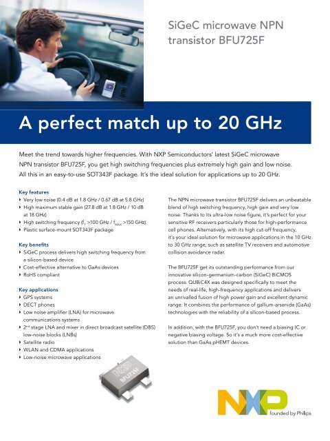
SiGeC microwave NPN<br />
transis<strong>to</strong>r BFU725F<br />
A <strong>perfect</strong> <strong>match</strong> <strong>up</strong> <strong>to</strong> <strong>20</strong> <strong>GHz</strong><br />
Meet the trend <strong>to</strong>wards higher frequencies. With <strong>NXP</strong> Semiconduc<strong>to</strong>rs’ latest SiGeC microwave<br />
NPN transis<strong>to</strong>r BFU725F, you get high switching frequencies plus extremely high gain and low noise.<br />
All this in an easy-<strong>to</strong>-use SOT343F package. It’s the ideal solution for applications <strong>up</strong> <strong>to</strong> <strong>20</strong> <strong>GHz</strong>.<br />
The NPN microwave transis<strong>to</strong>r BFU725F delivers an unbeatable<br />
blend of high switching frequency, high gain and very low<br />
noise. Thanks <strong>to</strong> its ultra-low noise fi gure, it’s <strong>perfect</strong> for your<br />
sensitive RF receivers particularly those for high-performance<br />
cell phones. Alternatively, with its high cut-off frequency,<br />
it’s your ideal solution for microwave applications in the 10 <strong>GHz</strong><br />
<strong>to</strong> 30 <strong>GHz</strong> range, such as satellite TV receivers and au<strong>to</strong>motive<br />
collision avoidance radar.<br />
The BFU725F get its outstanding performance from our<br />
innovative silicon-germanium-carbon (SiGeC) BiCMOS<br />
process. QUBiC4X was designed specifi cally <strong>to</strong> meet the<br />
needs of real-life, high-frequency applications and delivers<br />
an unrivalled fusion of high power gain and excellent dynamic<br />
range. It <strong>com</strong>bines the performance of gallium-arsenide (GaAs)<br />
technologies with the reliability of a silicon-based process.<br />
In addition, with the BFU725F, you don’t need a biasing IC or<br />
negative biasing voltage. So it’s a much more cost-effective<br />
solution than GaAs pHEMT devices.
Parameter Symbol Conditions Value<br />
Collec<strong>to</strong>r-emitter breakdown<br />
voltage<br />
www.nxp.<strong>com</strong><br />
©<strong>20</strong>06 <strong>NXP</strong> B.V.<br />
BV CEO I C = 1 mA; I B = 0 3.2 V<br />
Maximum collec<strong>to</strong>r current I C(max) 40 mA<br />
Transition frequency f T V CE = 2 V; I C = 25 mA; f = 2 <strong>GHz</strong> 68 <strong>GHz</strong><br />
Noise figure NF<br />
Maximum stable power gain MSG / G P(max)<br />
Quick reference data<br />
V CE = 2 V; I C = 5 mA; f = 1.8 <strong>GHz</strong>; Γ s = Γ opt<br />
V CE = 2 V; I C = 5 mA; f = 2.4 <strong>GHz</strong>; Γ s = Γ opt<br />
V CE = 2 V; I C = 5 mA; f = 5.8 <strong>GHz</strong>; Γ s = Γ opt<br />
V CE = 2 V; I C = 5 mA; f = 12 <strong>GHz</strong>; Γ s = Γ opt<br />
All rights reserved. Reproduction in whole or in part is prohibited without the prior written consent of the copyright owner.<br />
The information presented in this document does not form part of any quotation or contract, is believed <strong>to</strong> be accurate and<br />
reliable and may be changed without notice. No liability will be accepted by the publisher for any consequence of its use.<br />
Publication thereof does not convey nor imply any license under patent- or other industrial or intellectual property rights.<br />
0.4 dB<br />
0.45 dB<br />
0.7 dB<br />
1.0 dB<br />
V CE = 2 V; I C = 25 mA; f = 1.8 <strong>GHz</strong> 26.6 dB<br />
V CE = 2 V; I C = 25 mA; f = 2.4 <strong>GHz</strong> 25.5 dB<br />
V CE = 2 V; I C = 25 mA; f = 12 <strong>GHz</strong> 13 dB<br />
V CE = 2 V; I C = 25 mA; f = 5.8 <strong>GHz</strong> 17 dB<br />
Transition frequency as a function of collec<strong>to</strong>r current (typical values) Gain as a function of frequency (typical values)<br />
Date of release: Oc<strong>to</strong>ber <strong>20</strong>06<br />
Document order number: 9397 750 15784<br />
Printed in the Netherlands