Siliconization Of 60 GHz - Ali M. Niknejad
Siliconization Of 60 GHz - Ali M. Niknejad
Siliconization Of 60 GHz - Ali M. Niknejad

You also want an ePaper? Increase the reach of your titles
YUMPU automatically turns print PDFs into web optimized ePapers that Google loves.
FOCUSED<br />
ISSUE FEATURE<br />
<strong>Siliconization</strong><br />
of <strong>60</strong> <strong>GHz</strong><br />
<strong>Ali</strong> M. <strong>Niknejad</strong><br />
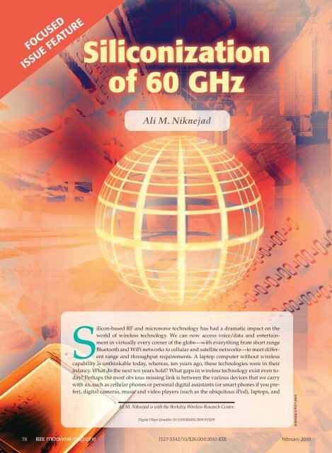
Silicon-based RF and microwave technology has had a dramatic impact on the<br />
world of wireless technology. We can now access voice/data and entertainment<br />
in virtually every corner of the globe—with everything from short range<br />
Bluetooth and WiFi networks to cellular and satellite networks—to meet different<br />
range and throughput requirements. A laptop computer without wireless<br />
capability is unthinkable today, whereas, ten years ago, these technologies were in their<br />
infancy. What do the next ten years hold? What gaps in wireless technology exist even today?<br />
Perhaps the most obvious missing link is between the various devices that we carry<br />
with us, such as cellular phones or personal digital assistants (or smart phones if you prefer),<br />
digital cameras, music and video players (such as the ubiquitous iPod), laptops, and<br />
<strong>Ali</strong> M. <strong>Niknejad</strong> is with the Berkeley Wireless Research Center.<br />
Digital Object Identifier 10.1109/MMM.2009.935209<br />
78 1527-3342/10/$26.00©2010 IEEE<br />
February 2010<br />
© BRAND X PICTURES
peripherals such as external hard drives and monitors.<br />
The case of the mobile smart phone is particularly<br />
important since the existing wireless connectivity is<br />
either too slow and power hungry (Bluetooth) or designed<br />
and optimized for longer ranges (WiFi). What<br />
is missing is a wireless universal connectivity that<br />
can support high data rates demanded by large data<br />
rate multimedia applications. Wireless technology has<br />
been conspicuously absent from MP3 music players<br />
(such as Apple’s iPod), which are ideal candidates for<br />
downloading music and video. While ultrawideband<br />
(UWB) technology using the 3–10 <strong>GHz</strong> band promised<br />
to fulfi ll these needs, it fell short in many ways, and,<br />
today, most of the start-up companies pursuing UWB<br />
have folded.<br />
Now many are making the same promises about<br />
<strong>60</strong>-<strong>GHz</strong> technology, so it is interesting to briefly<br />
explore the similarities and differences among these<br />
technologies. The UWB spectrum offered 7 <strong>GHz</strong> of<br />
bandwidth in the United States, but, when you consider<br />
a global UWB solution, the bandwidth is smaller<br />
(6–10 <strong>GHz</strong>) due to regulatory restrictions. More importantly,<br />
the allowed power transmission in this band is<br />
severely restricted by the Part 15 spectrum emission<br />
mask (24.3 dBm/MHz). By contrast, the maximum<br />
transmission power in the <strong>60</strong>-<strong>GHz</strong> band is orders of<br />
magnitude higher. In the United States, up to 39 dBm<br />
equivalent isotropically radiated power (EIRP) can<br />
be transmitted (due to the oxygen absorption in this<br />
band). Most UWB standards channelized the band<br />
into 500-MHz chunks, which limits the power even<br />
further, whereas most <strong>60</strong>-<strong>GHz</strong> standards use channels<br />
with over 1.5 <strong>GHz</strong> bandwidth. These differences translate<br />
into much higher capacity and much longer range<br />
communication in the <strong>60</strong>-<strong>GHz</strong> band compared to the<br />
UWB band. This is true even after the differences in<br />
propagation loss are taken into account. In fact, for<br />
the same aperture, a much higher gain antenna can<br />
be realized at <strong>60</strong> <strong>GHz</strong> compared to, say, 5 <strong>GHz</strong> due to<br />
the shorter wavelength. There are also clear disadvantages<br />
to operation at <strong>60</strong> <strong>GHz</strong> arising from the line-ofsight<br />
(LOS) nature of the channel. Interestingly, there<br />
are some similarities between UWB and <strong>60</strong> <strong>GHz</strong> in<br />
that both require a sophisticated baseband processor<br />
to handle the long delay spread relative to the symbol<br />
duration, which requires equalization or orthogonal<br />
frequency-division modulation (OFDM). Moreover,<br />
the wideband modulation requires a very fast analogto-digital<br />
converter (over 1 <strong>GHz</strong>), which can be a big<br />
source of power consumption if a high dynamic range<br />
signal is digitized directly. Techniques to lower the<br />
dynamic range of the baseband signal using mixedsignal<br />
techniques can benefit both kinds of systems.<br />
Applications of <strong>60</strong> <strong>GHz</strong><br />
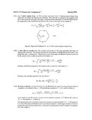
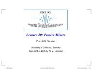
Figure 1 shows many scenarios where a high-speed<br />
Gb/s link can enhance the modern user’s experience.<br />
Point-to-Point Link<br />
100 m – 1 m<br />
100 Mb/s – 1 Gb/s<br />
Last Mile<br />
Broadband<br />
High-Speed<br />
Wireless<br />
LAN<br />
100 Mb/s M<br />
–1Gb/ –1Gb/s<br />
802.15.3 mmWIG<br />
Wireless Home<br />
Video and<br />
Data Link<br />
Figure 1. Potential applications for a high data rate<br />
<strong>60</strong>-<strong>GHz</strong> link.<br />
For example, the wireless LAN network today is limited<br />
to about 100 Mb/s, while the wired Ethernet cables<br />
are operating today at 1 Gb/s and will move to higher<br />
speeds in the near future. Many homes are converting<br />
to an optical connection which will offer high bandwidths<br />
to homes and offices, and users will demand a<br />
similar performance boost in their networks.<br />
One of the most exciting applications for UWB<br />
technology was a wireless USB-like connection. The<br />
ubiquity and simplicity of USB has transformed the<br />
computer industry. Users today buy peripherals and<br />
connect them to their PCs without having to worry<br />
about making the right connection. This is an example<br />
of a great success story in the PC industry. If we can<br />
similarly deliver a wireless USB-like connection with<br />
<strong>60</strong> <strong>GHz</strong>, the flexibility and ease of use will enhance<br />
the experience even further. Once users become accustomed<br />
to an untethered USB experience, there will be<br />
no turning back to cables.<br />
While existing applications will benefit from the<br />
higher speeds offered by <strong>60</strong> <strong>GHz</strong>, there are many<br />
emerging applications that will fundamentally change<br />
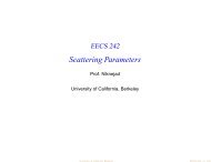
the way we use technology. Consider the hypothetical<br />
<strong>60</strong>-<strong>GHz</strong>-enabled iPhone, shown in Figure 2, which<br />
could use the <strong>60</strong>-<strong>GHz</strong> connection to download movies<br />
from a kiosk (perhaps at a train station or airport),<br />
transmit video to a larger screen for easier viewing<br />
(wireless docking), and connect to external peripherals<br />
such as hard disks and wired and optical networks.<br />
If such a device is realized with reasonable power consumption,<br />
we see that it can truly displace the laptop<br />
computer for most users.<br />
Now that analog TV has been discontinued in the<br />
United States, many users are upgrading their television<br />
sets to flat panel high-definition television<br />
(HDTV) screens. While the enhanced resolution and<br />
picture quality of digital TV is an exciting step forward,<br />
we have also taken a step backward by introducing<br />
February 2010 79
Figure 2. A high data rate <strong>60</strong> <strong>GHz</strong> link will enable universal<br />
untethered connectivity between consumer electronics<br />
and business devices. (From [20]. With kind permission of<br />
Springer Science and Business Media.)<br />
unnecessary complexity, accompanied by a rat’s nest<br />
of cables, into the life of the end user. Each user has to<br />
connect several devices to the TV (an antenna, a DVD<br />
player, a game player such as an XBox or Playstation, a<br />
DVR/cable set-top box, video cameras). As people convert<br />
to high-definition multimedia interface (HDMI),<br />
the number of cables reduces to the number of devices,<br />
as opposed to many setups that use component video<br />
and audio separately. While HDMI cables are inexpensive<br />
(unfortunately many are fooled into believing that<br />
the expensive cables are necessary and enhance quality),<br />
once a wireless solution is made available, it will be<br />
compelling to most users. It gives users the freedom to<br />
put devices where it is most convenient and to include<br />
mobile devices that can stream content to the TV (mobile<br />
phones, digital cameras, DVRs, netbooks/laptops, etc).<br />
Just as MP3 revolutionized the Internet and the<br />
music industry, we are now observing a similar transformation<br />
with video (and the popularity of Web sites<br />
such as YouTube). Disappointed by the limitations of<br />
current cable TV set-top boxes, many users are turning<br />
to the Internet for video content (television and videos).<br />
The Internet allows flexibility to share content and,<br />
most importantly, to move content from one device to<br />
another seamlessly. Many devices are vying to become<br />
the central hub of entertainment in the home theatre<br />
(Sony Playstation, XBox, Apple TV), but most are limited<br />
in their ability to universally play content from<br />
any device, particularly at the high resolution offered<br />
by HD video sources today. What is sorely lacking<br />
is a high throughput wireless connection that works<br />
universally with all devices. While some are trying to<br />
use the existing 802.11abgn networks to do this, there<br />
are fundamental issues (Shannon’s Theorem) with<br />
the amount of bandwidth and, hence, network capacity,<br />
which favors a high bandwidth solution such as<br />
<strong>60</strong> <strong>GHz</strong>. Moreover, the ability to send uncompressed<br />
data from a device to a display is a great advantage<br />
since it reduces the computational burden in video<br />
decompression. It also solves a common problem of<br />
dealing with encryption and incompatible codecs.<br />
Technology Choices<br />
Silicon technology has all but displaced gallium<br />
arsenide (GaAs) and other technologies for RF applications<br />
in the low <strong>GHz</strong> regime. A few niche applications,<br />
such as power amplifiers, remain as a stronghold<br />
but are also under threat by several upstarts in highvolume,<br />
low-power applications (mobile phones). For<br />
those with faith in Moore’s law, this was an inevitable<br />
consequence in scaling. Transistors became small<br />
enough and, consequently, fast enough to operate into<br />
the gigahertz frequencies.<br />
From a technology and performance perspective,<br />
silicon is not the obvious choice for <strong>60</strong>-<strong>GHz</strong> systems.<br />
Many non-silicon-based III-V technology choices come<br />
to mind that offer higher mobility and an insulating<br />
substrate (high Q passives) and, thus, high-frequency<br />
operation at moderately short channel lengths. Unfortunately,<br />
these technologies are expensive and have low<br />
manufacturing yields, thus they offer limited integration<br />
possibilities. Furthermore, these processes are not<br />
expected to scale in cost. If you believe <strong>60</strong> <strong>GHz</strong> is a high<br />
volume market, as is clearly evident from the potential<br />
applications that will enjoy <strong>60</strong> <strong>GHz</strong>, then silicon is in<br />
fact the obvious choice. Moreover, in price-sensitive<br />
consumer applications, complimentary metal-oxidesemiconductor<br />
(CMOS) is the right choice.<br />
But CMOS technology is not without problems.<br />
In addition to the well-known technical problems,<br />
such as lower performance (lower surface mobility<br />
of electrons, higher noise, lower gain, and a conductive<br />
substrate) and higher sensitivity to temperature,<br />
there are also economic challenges facing CMOS. After<br />
decades of unabated geometry scaling, today there is<br />
a lot of resistance to continue due to the prohibitively<br />
high costs (which only the microprocessor market<br />
has been able to endure) and an exponential increase<br />
in the leakage power of nanoscale digital circuits<br />
(which the microprocessor industry cannot tolerate).<br />
With the increased cost of scaled CMOS, one may wonder<br />
if there is a place for other technologies, especially<br />
close relatives such as silicon germanium (SiGe) bipolar<br />
CMOS (BiCMOS). Many argue that SiGe can realize the<br />
same performance as CMOS using older lithographic<br />
nodes, which are cheaper to manufacture. While this<br />
is certainly true, fortunately, we have already crossed<br />
the threshold, and today’s high-volume CMOS technologies<br />
such as the 90-nm node are capable of good<br />
performance at <strong>60</strong> <strong>GHz</strong> and are beginning to reduce<br />
in cost as the industry moves to 65 nm, 45 nm, and<br />
80 February 2010
even 32 nm. In fact, the performance boost of scaling<br />
CMOS is beginning to wane to fight leakage currents<br />
(higher threshold voltages in transistors, which translates<br />
into lower overdrive and lower speed) and other<br />
short-channel effects (mobility reduction to high field<br />
effects, higher gate/source/drain resistance due to<br />
thinner metal and junctions and smaller contacts, and<br />
lower quality passive devices due to the use of thinner<br />
metal and insulation layers). Moreover, the complexity<br />
of designing a chip in scaled CMOS has increased<br />
due to design for manufacturing rules, which require<br />
regularity in the layouts and densities of metal and<br />
junctions in the layout.<br />
Given these various conditions, the best process<br />
option for <strong>60</strong>-<strong>GHz</strong> CMOS appears to be 90- or 65-nm<br />
nodes. Measurements on 90-nm transistors at the<br />
Berkeley Wireless Research Center show an f T exceeding<br />
100 <strong>GHz</strong> (post-layout measurement) and an achievable<br />
f max over 200 <strong>GHz</strong>. At <strong>60</strong> <strong>GHz</strong>, we have measured<br />
a maximum stable gain of 8.5 dB and a unilateral gain<br />
over 12 dB. The minimum achievable noise figure of<br />
such devices is 3–4 dB (measured indirectly). The output<br />
power capability of a single device is about 10 mW.<br />
Using these numbers to estimate the range of a 1-<strong>GHz</strong><br />
channel <strong>60</strong>-<strong>GHz</strong> link, we arrive at: 110 dBm 2 Path-<br />
Loss . 284 dBm (kTB) 1 4 dB (NF) 1 10 dB (signalto-noise-ratio),<br />
or PathLoss , 80 dB. We have assumed<br />
low-gain antennas in this calculation, which is a valid<br />
assumption for a small portable device. This path loss<br />
corresponds to a distance of ,4 m LOS.<br />
Another important and related issue is the cost<br />
of packaging and testing. In most of today’s military<br />
millimeter-wave systems, the cost is dominated by<br />
these factors, and the die cost is a much smaller consideration.<br />
Keep in mind, though, that these low volume<br />
applications do not provide sufficient incentives<br />
to explore low-cost packaging options. Moreover,<br />
these applications are very<br />
performance-sensitive and<br />
would not compromise on<br />
the package if it resulted in<br />
a small decrease in performance.<br />
Consumer applications<br />
in contrast are so<br />
price-sensitive that this<br />
consideration completely outweighs<br />
other concerns. Given<br />
this constraint, it is expected<br />
that very-low-cost solutions<br />
for the packaging will be<br />
developed. To lower the cost<br />
of testing, it is imperative<br />
that circuit functionality is<br />
tested at baseband or at the<br />
digital interface, as millimeter-wave<br />
testing equipment<br />
is costly and more difficult<br />
TX Azimuth Angle (°)<br />
(sensitivity to cable displacement or compression, for<br />
instance) using built-in self-test (BIST). For example, if<br />
a transceiver is put into loop-back mode, it can test the<br />
functionality of the entire chip.<br />
<strong>60</strong> <strong>GHz</strong> Propagation<br />
In narrowband systems, multipath propagation manifests<br />
itself as flat fading in the band. Propagation at<br />
<strong>60</strong> <strong>GHz</strong>, on the other hand, has a long delay spread of<br />
about 100 ns (seen, for example, in the IEEE 802.15.3c<br />
library channel model), which translates into frequency-selective<br />
fading over the band of interest (say a 1<br />
<strong>GHz</strong> bandwidth). The most common way to deal with<br />
this kind of wireless channel is to use OFDM or multicarrier<br />
modulation. Unfortunately, OFDM is not an<br />
easy solution to adopt for <strong>60</strong> <strong>GHz</strong> owing to the high<br />
peak-to-average power ratio of the transmitted signal,<br />
the requirement for a high resolution analog-to-digital<br />
converter (ADC) and low phase noise voltage-controlled<br />
oscillator (VCO), and a highly linear receive path. In<br />
high-speed links, a mixed-signal equalization approach<br />
is utilized where a finite impulse response (FIR) filter<br />
is used to subtract out intersymbol interference, effectively<br />
equalizing the channel impulse response. Given<br />
the long delay spread at <strong>60</strong> <strong>GHz</strong>, this requires hundreds<br />
of FIR taps in the filter, which is costly in terms of silicon<br />
area and power consumption.<br />
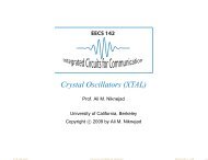
If we measure the actual <strong>60</strong> <strong>GHz</strong> channel, we<br />
observe that the propagation is quasi-optical, and<br />
simple ray tracing can be used to understand the<br />
multipath profile [1]. With careful measurements, one<br />
can observe several clusters of multipath propagation,<br />
as shown in the conference room measurement<br />
shown in Figure 3, and each cluster is easily identified<br />
as a LOS or non-LOS (NLOS) wave component that<br />
bounces off of walls, ceilings, or other objects. Each<br />
reflection results in approximately 10 dB of signal<br />
RX Power (dB) Relatively to Baseband Noise Level<br />
80<br />
30<br />
<strong>60</strong><br />
3<br />
5<br />
25<br />
40<br />
20<br />
20<br />
0<br />
1<br />
15<br />
–20<br />
–40<br />
2<br />
10<br />
–<strong>60</strong><br />
4<br />
5<br />
–80<br />
–80 –<strong>60</strong> –40 –20 0 20 40 <strong>60</strong><br />
0<br />
RX Azimuth Angle (°)<br />
February 2010 81<br />
4.5 m<br />
3.0 m<br />
Window RX<br />
4<br />
3<br />
5<br />
Door<br />
Figure 3. The measured <strong>60</strong> <strong>GHz</strong> channel in a conference room setting. The measurements<br />
clearly show evidence of quasi-optical propagation, e.g., simple to resolve multipath<br />
reflections. From [1].<br />
−<br />
+<br />
TX<br />
+<br />
1 2<br />
−
Magnitude Response<br />
<strong>60</strong> <strong>GHz</strong> Channel Measurement<br />
with 25 dBi Horn Antennas Separated by 40 cm<br />
–4<br />
–5<br />
–6<br />
–7<br />
–8<br />
–9<br />
–10<br />
–11<br />
–12<br />
–13<br />
–14<br />
–15<br />
57.5 58 58.5 59 59.5 <strong>60</strong> <strong>60</strong>.5 61 61.5 62 62.5<br />
Frequency (<strong>GHz</strong>)<br />
(a)<br />
I Channel (Normalized)<br />
1.2<br />
1<br />
0.8<br />
0.6<br />
0.4<br />
0.2<br />
0<br />
–0.2<br />
0 2 4 6<br />
Time (ns)<br />
8 10 12<br />
Q Channel (Normalized)<br />
1.2<br />
1<br />
0.8<br />
0.6<br />
0.4<br />
0.2<br />
0<br />
–0.2<br />
0 2 4 6<br />
Time (ns)<br />
(b)<br />
8 10 12<br />
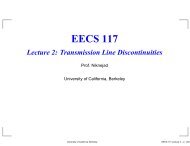
Figure 4. The <strong>60</strong> <strong>GHz</strong> channel response measured using<br />
highly directive 25 dBi horn antennas in the (a) frequency<br />
domain and (b) time domain [13].<br />
Input<br />
Image-Reject<br />
LNA<br />
Output<br />
PA<br />
×3<br />
Receiver Chip<br />
IFVGA<br />
Transmitter Chip<br />
×3<br />
Image-Reject<br />
Predriver<br />
PLL<br />
IF Mixer BB Amp<br />
PLL<br />
Ref. CLK<br />
÷2<br />
IFVGA<br />
IF Mixer<br />
Figure 5. Block diagram of IBM's SiGe <strong>60</strong> <strong>GHz</strong> frontend<br />
[5].<br />
÷2<br />
Ref. CLK<br />
I<br />
Q<br />
I<br />
Q<br />
power loss and reaches the receiver with an easily<br />
identifiable angle of arrival. If a directive antenna is<br />
employed, the antenna’s spatial selectivity reduces the<br />
delay spread considerably (,10 ns) as signals arriving<br />
after or before the strongest path come from different<br />
directions. A typical channel measurement using<br />
directive antennas, performed at the the Berkeley<br />
Wireless Research Center, is shown in Figure 4, both<br />
in the frequency domain and the time domain. We can<br />
clearly see that the delay spread is shorter than 10 ns,<br />
and frequency selectivity is on the order of 100 MHz,<br />
with fades as deep as 5 dB. In such a case, use of a<br />
mixed-signal baseband with modest ADC resolution<br />
is possible, and this approach has been pursued [2]<br />
where a 1 Gb/s I/Q baseband with a complex decision<br />
feedback equalizer (DFE) and 4-bit ADC was demonstrated<br />
with a power of 55 mW, capable of resolving up<br />
to 32 ns of delay spread.<br />
To overcome the high path loss and delay spread<br />
of the <strong>60</strong> <strong>GHz</strong> channel, we see that high-gain (highdirectivity)<br />
antennas are necessary. Directive antennas<br />
are usually physically large (such as a horn antenna),<br />
and require precise alignment. For mobile applications,<br />
sectorized antennas or phased arrays are much more<br />
convenient, providing gain without requiring alignment<br />
by the user. Phased arrays and high-gain antennas<br />
are probably the only practical ways to enable<br />
longer-range <strong>60</strong>-<strong>GHz</strong> communication. Other benefits<br />
include spatial power combining, which allows one to<br />
reduce the transmitted power per element, which may<br />
help to realize higher efficiencies.<br />
Phased arrays have been an active research topic,<br />
with many demonstrations in SiGe and CMOS [3], [4].<br />
Most of the phased arrays demonstrated to date suffer<br />
from very high power consumption and most are<br />
demonstrated in SiGe. The realization of a low power<br />
large array in CMOS at <strong>60</strong> <strong>GHz</strong> is still an outstanding<br />
problem to be solved.<br />
<strong>60</strong>-<strong>GHz</strong> Transceiver Demonstrations<br />
Many research groups are actively working on siliconbased<br />
<strong>60</strong>-<strong>GHz</strong> building blocks and full transceivers.<br />
The research team at IBM demonstrated full transceiver<br />
front-ends in a SiGe BiCMOS (0.13-µm) technology [5].<br />
A block diagram of the two-chip transceiver chipset<br />
is shown in Figure 5. A dual-conversion superheterodyne<br />
radio architecture was selected over a homodyne<br />
approach due to its lower carrier feed-through in<br />
the transmitter and better I/Q quadrature accuracy. A<br />
die photograph of the receiver is shown in Figure 6.<br />
The die size is 3.4 3 1.7 mm 2 to the outside of the pad<br />
frame. The low-noise amplifier (LNA) is at the lower<br />
left, and the spiral inductors in the receiver mixer and<br />
intermediate frequency (IF) variable gain amplifier (IF<br />
VGA) are visible to the right of the LNA. The frequency<br />
tripler is in the center, and the phase locked loop (PLL)<br />
occupies the right third of the chip. The chip contains<br />
82 February 2010
LNA<br />
Mix<br />
IFVGA<br />
Tripler<br />
PLL<br />
Figure 6. Chip microphotograph of IBM's <strong>60</strong> <strong>GHz</strong> receiver [5].<br />
more than 300 NPN transistors, more than 1,000 fieldeffect<br />
transistors (FETs), and more than 90 transmission<br />
lines and inductors. On-wafer measurements were<br />
made on the full receiver, including the PLL. The Rx<br />
power conversion gain is 38–40 dB and the NF is 5–<br />
6.7 dB. The image rejection is 30–40 dB, the third-order<br />
input-referred intercept point IIP3 is –30 dBm, and<br />
input P 1dB is –36 dBm. The receiver consumes 195 mA<br />
from 2.7 V, 50 mA of which is in the baseband output<br />
buffers. The receiver and transmitter PLL measurements<br />
show a VCO phase noise of –115 to –120 dBc/Hz<br />
at 10 MHz offset with a root mean square (RMS) jitter<br />
less than 1.5° integrated over 0.1–1 <strong>GHz</strong>.<br />
A die photograph of the transmitter is shown in Figure<br />
7. The die size is 4.0 3 1.6 mm 2 . The PA and the differential<br />
output pads are on the left, adjoined to the right<br />
LNA<br />
Quad<br />
Hybrid<br />
ESD Protection<br />
(Using Top Two Metal Layers)<br />
This Chip<br />
Power Map<br />
0°<br />
90°<br />
Downconverter<br />
LO BUF 4–7<br />
Modulator and<br />
Upconverter<br />
by the predriver, IF-to-RF mixer, IFVGA, and frequency<br />
tripler. The PLL occupies the right third of the chip,<br />
and the baseband-to-IF mixer contains the two spiral inductors<br />
at the top center. The transmitter chip contains<br />
more than 300 NPN transistors, more than 1,000 FETs, and<br />
more than 170 transmission lines and inductors. The transmitter<br />
conversion gain is 42–36 dB. P 1dB is 110 to 112 dBm<br />
while P sat is 116 to 117 dBm and the conversion gain is<br />
34–37 dB. With no dc offset correction applied, the external<br />
I/Q quadrature accuracy is within 62°. At P 1dB,<br />
the transmitter consumes 190 mA from 2.7 V and 72 mA<br />
from 4 V (PA).<br />
Research on CMOS millimeter-wave circuits is also<br />
very active, with many demonstrations of front-end<br />
receivers [6] and even complete transceivers [7]–[10].<br />
At the Berkeley Wireless Research Center, we have<br />
February 2010 83<br />
PA<br />
Predriver<br />
IFVGA<br />
Tripler<br />
PLL<br />
Figure 7. Chip microphotograph of IBM's <strong>60</strong> <strong>GHz</strong><br />
transmitter [5].<br />
I VGA<br />
Phase<br />
Rotator<br />
and DFE<br />
Quad<br />
Hybrid<br />
PRBS<br />
Generator<br />
TX CLK<br />
Figure 8. Block diagram of the Berkeley Wireless Research Center's <strong>60</strong> <strong>GHz</strong> CMOS transceiver [13].<br />
MUX<br />
Q VGA<br />
Wilkinson<br />
0°<br />
90°<br />
Pattern<br />
Memory<br />
RX CLK<br />
LO BUF 2<br />
LO BUF 3<br />
PRBS<br />
Checker<br />
Pattern<br />
Memory<br />
REF CLK<br />
(117 MHz) PLL<br />
Wilkinson<br />
LO BUF 1<br />
RX CLK<br />
VCO
ESD<br />
LNA<br />
Phase ROT./DFE<br />
Power<br />
AMP<br />
LO Buffer<br />
LO Buffer<br />
I VGA I Mixer<br />
Q VGA<br />
DAC +<br />
Mixer<br />
2.75 mm<br />
Quad Hybrid<br />
Q Mixer<br />
Quad<br />
Hybrid<br />
PLL<br />
demonstrated a fully integrated transceiver in 90 nm<br />
CMOS technology [11]. A block diagram of the transceiver<br />
is shown in Figure 8. Electrostatic discharge structures<br />
are absorbed into the LNA matching network, whereas<br />
the transmitter naturally benefits from the electrostatic<br />
discharge protection provided by the output transformer.<br />
On-chip quadrature couplers were used to produce<br />
I/Q signals in the receive path and I/Q LO signals in<br />
the transmit path. An on-chip PLL generates a <strong>60</strong>-<strong>GHz</strong><br />
LO from a 117 MHz reference frequency using a pushpush<br />
oscillator (core running at 30 <strong>GHz</strong>), which obviates<br />
the need for a <strong>60</strong>-<strong>GHz</strong> divider. The receive path uses<br />
transmission lines extensively for impedance matching<br />
and interconnect, whereas lumped transformers are<br />
employed in the transmitter. The transformers are also<br />
used to convert signal-ended LO signals to differential<br />
form for the Gilbert mixers and combine the power of<br />
two transistors in the output PA. The chip also includes<br />
a high-speed mixed signal baseband with 5 <strong>GHz</strong> bandwidth<br />
in each I/Q channel.<br />
The transceiver chip has dimensions of 2.5 3 2.75<br />
mm 2 (Figure 9). It operates from a 1.2 V supply and<br />
Wilkinson<br />
consumes 170 mW in transmit<br />
mode and 138 mW in receive<br />
mode. The PA is operated from<br />
a 1-V supply to improve reliability<br />
and has a simulated<br />
small signal gain of 14 dB at <strong>60</strong><br />
<strong>GHz</strong>. CW measurements verify<br />
that the PA can deliver 111<br />
dBm of saturated output power<br />
with a peak PAE of 14.6%. The<br />
receiver is a modification of a<br />
direct-conversion receiver demonstrated<br />
in [12]. The previous<br />
design had a measured noise<br />
figure of less than 6.2 dB across<br />
the <strong>60</strong>-<strong>GHz</strong> band. The addition<br />
of the electrostatic discharge<br />
structure and other modifications<br />
are expected to increase<br />
the noise figure of the receiver<br />
by approximately 1.2 dB. The<br />
VCO has a measured tuning<br />
range from <strong>60</strong>–64 <strong>GHz</strong> and has<br />
a phase noise of 2112 dBc/<br />
Hz at a 10-MHz offset from<br />
the <strong>60</strong>-<strong>GHz</strong> carrier. Electrostatic<br />
discharge measurements<br />
confirm that the structures provide up to 400-V machine<br />
model (MM) protection.<br />
Wireless testing was performed using a pair of<br />
25 dBi horn antenna. The antennas were placed approximately<br />
1 m apart for testing purposes. Due to the high<br />
data rates for which this transceiver was designed,<br />
data generation and checking were performed on-chip<br />
with pseudo-randon bit sequence (PRBS) generators/<br />
checkers and a pattern memory both on the transmit<br />
and receive side. The highest data rate achieved was<br />
4 Gb/s using quadrature phase-shift keying (QPSK)<br />
over the wireless channel. While, in theory, the transceiver<br />
should operate up to 10 Gb/s, the realized chip<br />
suffered from higher than expected I/Q mismatches.<br />
More details about he transceiver can be found in [13].<br />
SiBEAM has demonstrated and is currently shipping<br />
the first multigigabit <strong>60</strong>-<strong>GHz</strong> all-CMOS phased array<br />
system delivering 4 Gb/s in 10-m non-LOS environments<br />
[14]. The fully integrated chipsets enable the first<br />
WirelessHD compliant-systems in the market, supporting<br />
uncompressed and lossless wireless audio/video<br />
streaming of up to 1,080 p/<strong>60</strong> resolutions and frame<br />
rates with a wired equivalent robustness of less than a<br />
10 210 bit error rate. Figure 10 shows a chipset in a typical<br />
implementation. The two chip sets achieve complete<br />
antennas-to-bits integration, requiring minimal additional<br />
support hardware for integration into existing<br />
consumer electronics equipment (Blu-ray and HD DVD<br />
players and HD set-top boxes and displays). The radio<br />
chip’s packaging includes integrated <strong>60</strong>-<strong>GHz</strong> antennas,<br />
84 February 2010<br />
VCO<br />
2.5 mm<br />
Figure 9. Chip microphotograph of the Berkeley Wireless Research Center's <strong>60</strong> <strong>GHz</strong><br />
CMOS transceiver [13].<br />
Figure 10. SiBEAM's WirelessHD compliant <strong>60</strong> <strong>GHz</strong><br />
chipset. (Image courtesy of SiBEAM.)
simplifying board and system design by containing all<br />
high-frequency routing within the CMOS die and chip<br />
package. Achieving full 10 m NLOS coverage at the<br />
required data rates requires many independent antennas<br />
and partial radio chains. Thus, this fully integrated<br />
radio chip, containing all radio chains and antennas,<br />
represents a significant advance in the degree of parallelism<br />
achieved at the RF level for high-volume consumer<br />
wireless communications products.<br />
Standardization<br />
There are currently many standards for <strong>60</strong>-<strong>GHz</strong> wireless<br />
communication, including IEEE 802.15.3c [16], IEEE<br />
802.11ad (a high-speed WLAN network) [17], the<br />
ECMA-387 standard [18], WirelessHD [15], and the<br />
WiGig standard [19]. Each standard is formed by a different<br />
community of potential users of the technology,<br />
such as consumer electronics companies (WirelessHD)<br />
versus the PC industry (WiGig). Most of the standards<br />
are focusing on very high speed communication (1–5<br />
Gb/s) to enable wireless HDMI replacement.<br />
Unfortunately the process of standardization is<br />
highly political and controversial, often to the detriment<br />
of the technology and ultimately to the consumers.<br />
This was certainly the case for UWB technology and<br />
may have contributed to the delay of products and to<br />
the eventual downfall of UWB. It is imperative that the<br />
same mistakes are not made with <strong>60</strong> <strong>GHz</strong>. Even though<br />
different standards are needed for different applications,<br />
interoperability between the standards is key. For<br />
instance, a simple single carrier low range link should<br />
be the fall-back mode for all the different <strong>60</strong>-<strong>GHz</strong> radios.<br />
A single carrier is preferred, even though it may have a<br />
shorter range due to multipath effects, because it can be<br />
easily integrated into small low-power portable devices.<br />
This is in stark contrast to systems using OFDM, which<br />
require high power for the ADC and digital baseband<br />
processor (FFT operation).<br />
Conclusion<br />
Silicon based <strong>60</strong> <strong>GHz</strong> is a promising technology for<br />
high data rate communication. Gordon Moore is best<br />
known for his Law predicting the continued exponential<br />
growth in the number of transistors fabricated in<br />
silicon integrated circuits. In the same paper, though, he<br />
also predicted that someday the same trend may benefit<br />
microwave and millimeter-wave phased arrays. Today,<br />
with the convergence of high-speed silicon technology<br />
and the market demands for high data rates driven by<br />
high-definition video, <strong>60</strong> <strong>GHz</strong> is at the right place at<br />
the right time. Key challenges moving forward include<br />
power and size reduction to enable adoption in mobile<br />
devices and interoperability between the standardization<br />
efforts to ensure a universal <strong>60</strong>-<strong>GHz</strong> communication<br />
link, much like today’s wired USB cables. If <strong>60</strong> <strong>GHz</strong><br />
is widely deployed in consumer electronics devices, we<br />
may have to coin a new millimeter-wave Moore’s Law.<br />
Acknowledgments<br />
The <strong>60</strong>-<strong>GHz</strong> research using silicon technology was<br />
sponsored by the visionary DARPA TEAM Program,<br />
managed by Dr. Reuss, Dr. Radack, and Dr. Fritze. The<br />
author thanks NSF (Infrastructure Grant No. 0403427),<br />
DARPA and the FCRP C2S2 program for continued<br />
funding of millimeter-wave silicon research. The<br />
authors also thank ST Microelectronics and IBM for<br />
the donation of silicon foundry services.<br />
References<br />
[1] A. Maltsev, R. Maslennikov, A. Sevastyanov, A. Khoryaev, and A. Lomayev,<br />
“Experimental investigations of <strong>60</strong> <strong>GHz</strong> wireless systems in office<br />
environment,” IEEE J. Select. Areas Commun., vol. 27, no. 8, Oct. 2009.<br />
[2] D. A. Sobel and R. W. Brodersen, “A 1Gbps mixed-signal analog<br />
front end for a <strong>60</strong> <strong>GHz</strong> wireless receiver,” in Proc. IEEE Symp. VLSI<br />
Circuits, June 2008, pp. 156–157.<br />
[3] A. Babakhani, X. Guan, A. Komijani, A. Natarajan, and A. Hajimiri,<br />
“A77-<strong>GHz</strong> phased array transceiver with on-chip antennas<br />
in silicon: Receiver and antennas,” IEEE J. Solid-State Circuits, vol.<br />
41, no. 12, pp. 2795–806, Dec. 2006.<br />
[4] K. Scheir, S. Bronckers, J. Borremans, P. Wambacq, and Y. Rolain,<br />
“A 52<strong>GHz</strong> phased-array receiver front-end in 90nm digital CMOS,”<br />
in ISSCC Dig. Tech. Papers, Feb. 2008, pp. 184–185.<br />
[5] S. K. Reynolds, B. A. Floyd, U. R. Pfeiffer, T. Beukema, J. Grzyb, C.<br />
Haymes, B. Gaucher, and M. Soyuer, “A silicon <strong>60</strong>-<strong>GHz</strong> receiver<br />
and transmitter chipset for broadband communications,” IEEE J.<br />
Solid-State Circuits, vol. 41, no. 12, pp. 2820–2831, Dec. 2006.<br />
[6] A. Parsa and B. Razavi, “A <strong>60</strong><strong>GHz</strong> CMOS receiver using a 30<strong>GHz</strong><br />
LO,” in ISSCC Dig. Tech. Papers, Feb. 2008, pp. 190–191.<br />
[7] S. Pinel, S. Sarkar, P. Sen, B. Perumana, D. Yeh, D. Dawn, and J.<br />
Laskar, “<strong>60</strong><strong>GHz</strong> single chip 90 CMOS radio,” in ISSCC Dig. Tech.<br />
Papers, Feb. 2008.<br />
[8] J. Lee, Y. Huang, Y. Chen, H. Lu, and C. Chang, “A low-power fully integrated<br />
<strong>60</strong><strong>GHz</strong> transceiver system with OOK modulation and on-board<br />
antenna assembly,” in ISSCC Dig. Tech. Papers, Feb. 2009, pp. 316–317.<br />
[9] A. Tomkins, R. A. Aroca, T. Yamamoto, S. T. Nicolson, Y. Doi, and S. P.<br />
Voinigescu, “A zero-IF <strong>60</strong><strong>GHz</strong> transceiver in 65nm CMOS with > 3.5Gb/s<br />
links,” in IEEE CICC Dig., San Jose, CA, Sept. 2008, pp. 471–474.<br />
[10] C.-H. Wang, H.-Y. Chang, P.-S. Wu, K.-Y. Lin, T.-W. Huang, H. Wang,<br />
and C.-H. Chen, “A <strong>60</strong>-<strong>GHz</strong> low power six-port transceiver for gigabit<br />
software-defined transceiver,” in ISSCC Dig. Tech. Papers, Feb. 2007.<br />
[11] C. Marcu, D. Chowdhury, C. Thakkar, L.-K. Kong, M. Tabesh, J.-D.<br />
Park, Y. Wang, B. Afshar, A. Gupta, A. Arbabian, S. Gambini, R.<br />
Zamani, A. M. <strong>Niknejad</strong>, and E. Alon, “A 90 nm CMOS low-power<br />
<strong>60</strong><strong>GHz</strong> transceiver with integrated baseband circuitry,” in ISSCC<br />
Dig. Tech. Papers, Feb. 2009, pp. 314–315.<br />
[12] B. Afshar, Y. Wang, and A. M. <strong>Niknejad</strong>, “A robust 24mW <strong>60</strong> <strong>GHz</strong><br />
receiver in 90 nm standard CMOS,” in ISSCC Dig. Tech. Papers, Feb.<br />
2008, pp. 182–183.<br />
[13] C. Marcu, D. Chowdhury, C. Thakkar, J.-D. Park, L.-K. Kong, M.<br />
Tabesh, Y. Wang, B. Afshar, A. Gupta, A. Arbabian, S. Gambini, R.<br />
Zamani, E. Alon, and A. M. <strong>Niknejad</strong>, “A 90 nm CMOS low-power<br />
<strong>60</strong><strong>GHz</strong> transceiver with integrated baseband circuitry,” IEEE J. Solid-<br />
State Circuits, to be published.<br />
[14] J. M. Gilbert, C. H. Doan, S. Emami, and C. B. Shung, “A 4-Gbps<br />
uncompressed wireless HD A/V transceiver chipset,” IEEE Micro,<br />
vol. 28, no. 2, pp. 56–64, Mar./Apr. 2008.<br />
[15] WirelessHD. [Online]. Available: http://www.wirelesshd.org<br />
[16] IEEE 802.11 Working Group, Wireless PAN Task Group 3c. (2009).<br />
Millimeter Wave Alternative PHY. [Online]. Available: http://<br />
www.ieee802.org/15/pub/TG3c.html<br />
[17] IEEE 802.11 Working Group. Very high throughput in <strong>60</strong> <strong>GHz</strong>.<br />
[Online]. Available: http://www.ieee802.org/11/Reports/tgad_<br />
update.htm<br />
[18] Standard ECMA-387. (2008, Dec.). High Rate <strong>60</strong> <strong>GHz</strong> PHY, MAC<br />
and HDMI PAL [Online]. Available http://www.ecma-international.org/publications/standards/Ecma-387.htm<br />
[19] Wireless Gigabit Alliance. [Online]. Available: http://wirelessgigabitalliance.org/<br />
[20] A. M. <strong>Niknejad</strong> and H. Hashemi, Eds., mm-Wave Silicon Technology:<br />
<strong>60</strong> <strong>GHz</strong> and Beyond, Springer, 2008.<br />
February 2010 85