Siliconization Of 60 GHz - Ali M. Niknejad
Siliconization Of 60 GHz - Ali M. Niknejad
Siliconization Of 60 GHz - Ali M. Niknejad

Create successful ePaper yourself
Turn your PDF publications into a flip-book with our unique Google optimized e-Paper software.
even 32 nm. In fact, the performance boost of scaling<br />
CMOS is beginning to wane to fight leakage currents<br />
(higher threshold voltages in transistors, which translates<br />
into lower overdrive and lower speed) and other<br />
short-channel effects (mobility reduction to high field<br />
effects, higher gate/source/drain resistance due to<br />
thinner metal and junctions and smaller contacts, and<br />
lower quality passive devices due to the use of thinner<br />
metal and insulation layers). Moreover, the complexity<br />
of designing a chip in scaled CMOS has increased<br />
due to design for manufacturing rules, which require<br />
regularity in the layouts and densities of metal and<br />
junctions in the layout.<br />
Given these various conditions, the best process<br />
option for <strong>60</strong>-<strong>GHz</strong> CMOS appears to be 90- or 65-nm<br />
nodes. Measurements on 90-nm transistors at the<br />
Berkeley Wireless Research Center show an f T exceeding<br />
100 <strong>GHz</strong> (post-layout measurement) and an achievable<br />
f max over 200 <strong>GHz</strong>. At <strong>60</strong> <strong>GHz</strong>, we have measured<br />
a maximum stable gain of 8.5 dB and a unilateral gain<br />
over 12 dB. The minimum achievable noise figure of<br />
such devices is 3–4 dB (measured indirectly). The output<br />
power capability of a single device is about 10 mW.<br />
Using these numbers to estimate the range of a 1-<strong>GHz</strong><br />
channel <strong>60</strong>-<strong>GHz</strong> link, we arrive at: 110 dBm 2 Path-<br />
Loss . 284 dBm (kTB) 1 4 dB (NF) 1 10 dB (signalto-noise-ratio),<br />
or PathLoss , 80 dB. We have assumed<br />
low-gain antennas in this calculation, which is a valid<br />
assumption for a small portable device. This path loss<br />
corresponds to a distance of ,4 m LOS.<br />
Another important and related issue is the cost<br />
of packaging and testing. In most of today’s military<br />
millimeter-wave systems, the cost is dominated by<br />
these factors, and the die cost is a much smaller consideration.<br />
Keep in mind, though, that these low volume<br />
applications do not provide sufficient incentives<br />
to explore low-cost packaging options. Moreover,<br />
these applications are very<br />
performance-sensitive and<br />
would not compromise on<br />
the package if it resulted in<br />
a small decrease in performance.<br />
Consumer applications<br />
in contrast are so<br />
price-sensitive that this<br />
consideration completely outweighs<br />
other concerns. Given<br />
this constraint, it is expected<br />
that very-low-cost solutions<br />
for the packaging will be<br />
developed. To lower the cost<br />
of testing, it is imperative<br />
that circuit functionality is<br />
tested at baseband or at the<br />
digital interface, as millimeter-wave<br />
testing equipment<br />
is costly and more difficult<br />
TX Azimuth Angle (°)<br />
(sensitivity to cable displacement or compression, for<br />
instance) using built-in self-test (BIST). For example, if<br />
a transceiver is put into loop-back mode, it can test the<br />
functionality of the entire chip.<br />
<strong>60</strong> <strong>GHz</strong> Propagation<br />
In narrowband systems, multipath propagation manifests<br />
itself as flat fading in the band. Propagation at<br />
<strong>60</strong> <strong>GHz</strong>, on the other hand, has a long delay spread of<br />
about 100 ns (seen, for example, in the IEEE 802.15.3c<br />
library channel model), which translates into frequency-selective<br />
fading over the band of interest (say a 1<br />
<strong>GHz</strong> bandwidth). The most common way to deal with<br />
this kind of wireless channel is to use OFDM or multicarrier<br />
modulation. Unfortunately, OFDM is not an<br />
easy solution to adopt for <strong>60</strong> <strong>GHz</strong> owing to the high<br />
peak-to-average power ratio of the transmitted signal,<br />
the requirement for a high resolution analog-to-digital<br />
converter (ADC) and low phase noise voltage-controlled<br />
oscillator (VCO), and a highly linear receive path. In<br />
high-speed links, a mixed-signal equalization approach<br />
is utilized where a finite impulse response (FIR) filter<br />
is used to subtract out intersymbol interference, effectively<br />
equalizing the channel impulse response. Given<br />
the long delay spread at <strong>60</strong> <strong>GHz</strong>, this requires hundreds<br />
of FIR taps in the filter, which is costly in terms of silicon<br />
area and power consumption.<br />
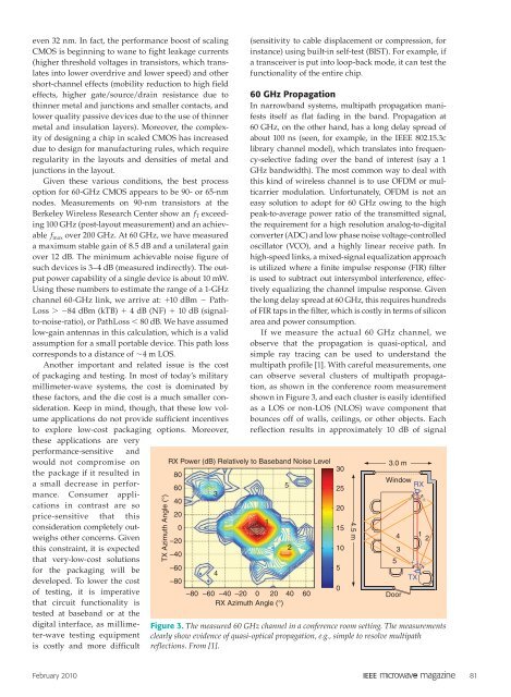
If we measure the actual <strong>60</strong> <strong>GHz</strong> channel, we<br />
observe that the propagation is quasi-optical, and<br />
simple ray tracing can be used to understand the<br />
multipath profile [1]. With careful measurements, one<br />
can observe several clusters of multipath propagation,<br />
as shown in the conference room measurement<br />
shown in Figure 3, and each cluster is easily identified<br />
as a LOS or non-LOS (NLOS) wave component that<br />
bounces off of walls, ceilings, or other objects. Each<br />
reflection results in approximately 10 dB of signal<br />
RX Power (dB) Relatively to Baseband Noise Level<br />
80<br />
30<br />
<strong>60</strong><br />
3<br />
5<br />
25<br />
40<br />
20<br />
20<br />
0<br />
1<br />
15<br />
–20<br />
–40<br />
2<br />
10<br />
–<strong>60</strong><br />
4<br />
5<br />
–80<br />
–80 –<strong>60</strong> –40 –20 0 20 40 <strong>60</strong><br />
0<br />
RX Azimuth Angle (°)<br />
February 2010 81<br />
4.5 m<br />
3.0 m<br />
Window RX<br />
4<br />
3<br />
5<br />
Door<br />
Figure 3. The measured <strong>60</strong> <strong>GHz</strong> channel in a conference room setting. The measurements<br />
clearly show evidence of quasi-optical propagation, e.g., simple to resolve multipath<br />
reflections. From [1].<br />
−<br />
+<br />
TX<br />
+<br />
1 2<br />
−