Siliconization Of 60 GHz - Ali M. Niknejad
Siliconization Of 60 GHz - Ali M. Niknejad
Siliconization Of 60 GHz - Ali M. Niknejad

You also want an ePaper? Increase the reach of your titles
YUMPU automatically turns print PDFs into web optimized ePapers that Google loves.
Magnitude Response<br />
<strong>60</strong> <strong>GHz</strong> Channel Measurement<br />
with 25 dBi Horn Antennas Separated by 40 cm<br />
–4<br />
–5<br />
–6<br />
–7<br />
–8<br />
–9<br />
–10<br />
–11<br />
–12<br />
–13<br />
–14<br />
–15<br />
57.5 58 58.5 59 59.5 <strong>60</strong> <strong>60</strong>.5 61 61.5 62 62.5<br />
Frequency (<strong>GHz</strong>)<br />
(a)<br />
I Channel (Normalized)<br />
1.2<br />
1<br />
0.8<br />
0.6<br />
0.4<br />
0.2<br />
0<br />
–0.2<br />
0 2 4 6<br />
Time (ns)<br />
8 10 12<br />
Q Channel (Normalized)<br />
1.2<br />
1<br />
0.8<br />
0.6<br />
0.4<br />
0.2<br />
0<br />
–0.2<br />
0 2 4 6<br />
Time (ns)<br />
(b)<br />
8 10 12<br />
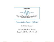
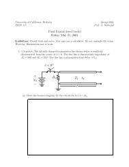
Figure 4. The <strong>60</strong> <strong>GHz</strong> channel response measured using<br />
highly directive 25 dBi horn antennas in the (a) frequency<br />
domain and (b) time domain [13].<br />
Input<br />
Image-Reject<br />
LNA<br />
Output<br />
PA<br />
×3<br />
Receiver Chip<br />
IFVGA<br />
Transmitter Chip<br />
×3<br />
Image-Reject<br />
Predriver<br />
PLL<br />
IF Mixer BB Amp<br />
PLL<br />
Ref. CLK<br />
÷2<br />
IFVGA<br />
IF Mixer<br />
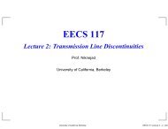
Figure 5. Block diagram of IBM's SiGe <strong>60</strong> <strong>GHz</strong> frontend<br />
[5].<br />
÷2<br />
Ref. CLK<br />
I<br />
Q<br />
I<br />
Q<br />
power loss and reaches the receiver with an easily<br />
identifiable angle of arrival. If a directive antenna is<br />
employed, the antenna’s spatial selectivity reduces the<br />
delay spread considerably (,10 ns) as signals arriving<br />
after or before the strongest path come from different<br />
directions. A typical channel measurement using<br />
directive antennas, performed at the the Berkeley<br />
Wireless Research Center, is shown in Figure 4, both<br />
in the frequency domain and the time domain. We can<br />
clearly see that the delay spread is shorter than 10 ns,<br />
and frequency selectivity is on the order of 100 MHz,<br />
with fades as deep as 5 dB. In such a case, use of a<br />
mixed-signal baseband with modest ADC resolution<br />
is possible, and this approach has been pursued [2]<br />
where a 1 Gb/s I/Q baseband with a complex decision<br />
feedback equalizer (DFE) and 4-bit ADC was demonstrated<br />
with a power of 55 mW, capable of resolving up<br />
to 32 ns of delay spread.<br />
To overcome the high path loss and delay spread<br />
of the <strong>60</strong> <strong>GHz</strong> channel, we see that high-gain (highdirectivity)<br />
antennas are necessary. Directive antennas<br />
are usually physically large (such as a horn antenna),<br />
and require precise alignment. For mobile applications,<br />
sectorized antennas or phased arrays are much more<br />
convenient, providing gain without requiring alignment<br />
by the user. Phased arrays and high-gain antennas<br />
are probably the only practical ways to enable<br />
longer-range <strong>60</strong>-<strong>GHz</strong> communication. Other benefits<br />
include spatial power combining, which allows one to<br />
reduce the transmitted power per element, which may<br />
help to realize higher efficiencies.<br />
Phased arrays have been an active research topic,<br />
with many demonstrations in SiGe and CMOS [3], [4].<br />
Most of the phased arrays demonstrated to date suffer<br />
from very high power consumption and most are<br />
demonstrated in SiGe. The realization of a low power<br />
large array in CMOS at <strong>60</strong> <strong>GHz</strong> is still an outstanding<br />
problem to be solved.<br />
<strong>60</strong>-<strong>GHz</strong> Transceiver Demonstrations<br />
Many research groups are actively working on siliconbased<br />
<strong>60</strong>-<strong>GHz</strong> building blocks and full transceivers.<br />
The research team at IBM demonstrated full transceiver<br />
front-ends in a SiGe BiCMOS (0.13-µm) technology [5].<br />
A block diagram of the two-chip transceiver chipset<br />
is shown in Figure 5. A dual-conversion superheterodyne<br />
radio architecture was selected over a homodyne<br />
approach due to its lower carrier feed-through in<br />
the transmitter and better I/Q quadrature accuracy. A<br />
die photograph of the receiver is shown in Figure 6.<br />
The die size is 3.4 3 1.7 mm 2 to the outside of the pad<br />
frame. The low-noise amplifier (LNA) is at the lower<br />
left, and the spiral inductors in the receiver mixer and<br />
intermediate frequency (IF) variable gain amplifier (IF<br />
VGA) are visible to the right of the LNA. The frequency<br />
tripler is in the center, and the phase locked loop (PLL)<br />
occupies the right third of the chip. The chip contains<br />
82 February 2010