
You also want an ePaper? Increase the reach of your titles
YUMPU automatically turns print PDFs into web optimized ePapers that Google loves.
<strong>REMOTE</strong> <strong>CONTROL</strong> <strong>CAR</strong> <strong>ALARM</strong> <strong>SYSTEM</strong><br />
Email: technicalsupport@stadiumcp.co.uk
INTRODUCTION<br />
SPARKRITE SR90<br />
<strong>REMOTE</strong> <strong>CAR</strong> <strong>ALARM</strong> <strong>SYSTEM</strong><br />
The Sparkrite SR90 advanced remote control alarm system incorporates the<br />
latest "state-of-the-art" microprocessor technology offering the ultimate in<br />
product reliability and performance.<br />
Features:<br />
• Radio remote control-DTI approved. Instant arming and disarming.<br />
• Remote control panic feature-gives personal protection sounding siren for<br />
up to 50 seconds.<br />
• Automatic (passive) arming feature. Alarm arms automatically 20 seconds<br />
after last door closure. Disarmed via remote control or ignition key.<br />
• Powerful built-in 128dB siren.<br />
• Current sensing-detects interior light switching on.<br />
• Door switch sensing detects opening of doors, boot or bonnet.<br />
• Hazard lights flash and siren chirps on arm/disarm.<br />
• Audible chirp over-ride option.<br />
• Alarm armed LED (light emitting diode) as a visible deterrent.<br />
• Cooling fan sensing circuit-prevents false triggering of current sensing<br />
circuit.<br />
• Attempted entry display. LED flashes a code if vehicle has been tampered<br />
with.<br />
• Siren sounds for 50 seconds (nominal) when the alarm is triggered.<br />
• Automatic reset, giving continuous protection until disarmed by remote<br />
control.<br />
• Fuse protected against attempts to over-ride circuitry.<br />
• Sensor connection (optional)-Quick-fit plug allows connection of Sparkrite<br />
Ultrasonic Interior Protection unit SR901 or Space Sensor SR902.<br />
• Security circuit-prevents accidental arming whilst driving.<br />
2
<strong>REMOTE</strong> <strong>CONTROL</strong> RADIO TRANSMITTER<br />
The radio transmitter conforms to DTI legislation with each alarm allocated a<br />
unique security code. Additional transmitters are available on special order<br />
from your nearest stockist, or direct from Sparkrite using the enclosed order<br />
form, quoting your serial number on the back of the remote control.<br />
ARMING<br />
To arm the SR90 alarm, proceed as follows:<br />
Remove the ignition key and leave the vehicle ensuring all doors, windows,<br />
sunroof, boot and bonnet are closed.<br />
Press the button on the remote control transmitter once. The indicators on the<br />
vehicle will flash once, coinciding with a single chirp (if selected) from the<br />
siren, and the dashboard LED will also flash (following the 20 second arming<br />
delay), at approximately one second intervals to show that the system is<br />
armed.<br />
If passive arming is selected, the SR90 will arm automatically following<br />
closure of the last door (see arming control).<br />
DISARMING<br />
To disarm the alarm, press the transmitter button once, the indicators will flash<br />
three times, coinciding with two chirps (if selected) from the siren. Check that<br />
the dashboard LED has stopped flashing and unlock the vehicle as normal.<br />
If you trigger the alarm accidentally, follow the normal disarming procedure<br />
but keep the control button depressed until the alarm stops.<br />
Note: When the alarm is armed, the current sensing and ultrasonic circuits<br />
(optional) will not trigger the alarm until a 30 second exit delay has expired.<br />
This is to allow movement inside the vehicle and in some cases, courtesy light<br />
delays to cease.<br />
<strong>REMOTE</strong> PANIC<br />
If the transmitter button is pressed and held for three seconds, the SR90 will<br />
trigger and commence an alarm cycle as a possible means of summoning<br />
help, a very useful defense in case of attack or assault.<br />
3
FEATURE SELECTION<br />
The SR90 is specifically designed to give a choice of operating features for<br />
your convenience. These are three ON/OFF switches as follows: -<br />
1. AUDIBLE CHIRP<br />
Controls arm/disarm chirp only. Turn to OFF for no audible chirp.<br />
2. PASSIVE ARMING <strong>CONTROL</strong><br />
If the passive (automatic) arming feature is required, select the ON position of<br />
the slide switch.<br />
With the switch in the ON position, the alarm will automatically commence the<br />
arming sequence 10 seconds AFTER the last door is closed, and will be fully<br />
armed after 20 seconds. The hazard lights will flash once and the siren will<br />
chirp, (if selected), indicating the vehicle is protected.<br />
The alarm is disarmed using the remote control as normal or by switching on<br />
the ignition within 10 seconds.<br />
In the OFF position, use the remote control for Instant ARM and DISARM.<br />
3. CURRENT SENSING<br />
Current sensing is the most common method of triggering an alarm. This<br />
circuit operates by detecting the current drained from the vehicle's battery<br />
when the interior light is switched on, which subsequently triggers the alarm.<br />
When the SR90 is installed, it is recommended that the slide switch is set in<br />
the ON position. If your vehicle is fitted with an electrically operated, pulsed<br />
clockwork clock (normally fitted on vehicles pre 1980) or a car telephone<br />
which accepts incoming calls when the ignition is off, it can cause false<br />
triggering of the alarm. In this instance, slide the current sensing switch to the<br />
OFF position. It will then be necessary to connect the BLUE wire to the door<br />
switches as described later.<br />
IMPORTANT: The SR90 switches are factory set to the following positions:<br />
Current - ON<br />
Passive - OFF<br />
Chirp–ON<br />
4
FITTING INSTRUCTIONS<br />
Suitable for 12V negative earth vehicles only.<br />
IMPORTANT: The vehicle battery must be disconnected during the<br />
installation procedure, except where necessary to carry out circuit tests<br />
specified.<br />
TESTING PROCEDURE<br />
If you are unable to easily identify the correct wire on the vehicle to make a<br />
connection, it is recommended a 12 DC test lamp or test screwdriver is used.<br />
Care must be taken to ensure the wire being tested is not shorted to earth<br />
(chassis) via the wire or probe of the tester.<br />
INSTALLATION NOTES<br />
a) The harness is supplied with in-line fuses in the RED, VIOLET and GREY<br />
leads. If any of the fuses blow, ensure replacements of the correct value<br />
are used.<br />
b) When mounting wires around the engine compartment and through the<br />
bulkhead inside the vehicle, ensure the wire insulation cannot be damaged<br />
on sharp metal edges, protecting where necessary with insulation tape or<br />
rubber sleeving.<br />
c) It is recommended that where possible, connections to the vehicle wiring<br />
should be made at the steering column or fusebox. This will prevent<br />
anyone tampering with the alarm from outside the vehicle.<br />
d) Do not switch off courtesy, or boot lights (if fitted) or the current sensing<br />
circuit will not operate. Replace light bulbs when they fail.<br />
MOUNTING THE MAIN <strong>ALARM</strong> MODULE ~<br />
Mount the alarm in the vehicle's engine compartment, close to the front of the<br />
vehicle and in a position where it is difficult to gain access to the alarm wiring<br />
from below the car. Also ensure the alarm is located away from areas of<br />
extreme heat and at least 12" away from the ignition system.<br />
Using the alarm mounting bracket as a template, drill 2 holes, and secure the<br />
bracket to the car bodywork using self-tapping screws supplied.<br />
5
MAIN CABLE HARNESS WIRING<br />
Connections to the vehicle wiring will be made using scotchlok connectors as<br />
follows;<br />
STOP<br />
HARNESS LOCATION<br />
Feed the 3 and 5 way harness through the flexible rubber sleeve and position<br />
the assembly to the rear of the main alarm module.<br />
IMPORTANT: Do not connect wiring harnesses to the alarm until all wiring<br />
has been connected.<br />
ARMED INDICATOR LED<br />
Remove the retaining nut from the LED bezel. Drill a suitable mounting hole in<br />
the dashboard where the armed indicator may be seen from outside the<br />
vehicle, as a visible deterrent.<br />
Feed the two way connector through the hole and secure the LED bezel with<br />
the retaining nut. Route the wires through a bulkhead grommet to the alarm<br />
and push them carefully through the flexible rubber sleeve. Insert the two way<br />
connector into the socket on the rear of the alarm.<br />
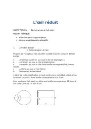
Operation:<br />
ADDITIONAL<br />
WIRE<br />
METAL<br />
INSERT<br />
EXISTING<br />
WIRE<br />
Place the wires in position as shown<br />
and hold carefully in place whilst<br />
pressing firmly in the metal insert with<br />
pliers. The metal insert automatically<br />
strips the insulation from wires at<br />
points of contact.<br />
When the alarm is armed, the red LED will illuminate. Following the 20 second<br />
exit delay, the LED will flash at 1 second intervals to indicate the SR90 is fully<br />
armed. If the alarm is triggered and completes a full alarm cycle (50 seconds),<br />
the LED will flash at half second intervals to indicate that a violation has<br />
occurred.<br />
6<br />
Close the locking tab to hold the connector<br />
together
WIRING DIAGRAM<br />
WIRING CONNECTIONS<br />
GREEN - RADIO AERIAL<br />
The GREEN aerial wire must not be cut or connected to anything metal,<br />
otherwise the operating range will be affected. Tape the antenna to the main<br />
harness to achieve optimum performance.<br />
VIOLET AND GREY-INDICATOR LIGHTS<br />
VIOLET Using the vehicle's wiring diagram or 12V test lamp, locate the wire<br />
on the indicator switch or direct on any indicator lamp, which<br />
illuminates the test bulb when the RIGHT hand indicator flashes on<br />
and off. Connect this wire to the VIOLET wire on the alarm harness<br />
using a scotchlock connector.<br />
GREY Repeat the above procedure, connecting the GREY wire to the LEFT<br />
hand indicator circuit.<br />
PINK -IGNITION INPUT<br />
Using a test lamp, locate a 12 volt supply wire at the ignition switch or fusebox<br />
which is live only in the STARTING and RUN positions of the ignition key.<br />
Connect the PINK wire using a scotchlock connector to this wire.<br />
Note: The auxiliary power supply to radios/cassettes must not be used.<br />
7
YELLOW - ELECTRIC FAN INHIBIT<br />
If the cooling fan is switched by the ignition or no electric fan is fitted, insulate<br />
the YELLOW wire and leave disconnected.<br />
If your vehicle is fitted with a thermostatically controlled cooling fan which<br />
operates with the ignition switched off, the YELLOW lead must be connected<br />
to prevent false triggering of the alarm.<br />
The majority of modern vehicles have "positive" switched fans and the<br />
YELLOW wire should be connected as shown in Fig. 1.<br />
If the cooling fan is “earth" switched as shown in Fig. 2, it will be necessary to<br />
slide the current sensing switch on the main alarm module to the OFF<br />
position, insulate the YELLOW wire and leave disconnected.<br />
BLACK WIRE – EARTH<br />
The BLACK wire must be connected to a good clean metal earthing point on<br />
the bodywork of the vehicle.<br />
Drill a suitable hole within 12" of the main alarm unit and secure the BLACK<br />
wire through the ring terminal using the self-tapping screw supplied.<br />
8
BLUE-DOOR SWITCHES<br />
If the vehicle is not fitted with courtesy light switches on the rear doors, it is<br />
recommended additional switches (SR910) are fitted and connected to the<br />
courtesy light circuit as shown in Fig. 3.<br />
If the current sensing switch on the main alarm is in the ON position, and your<br />
courtesy light works on all four doors, proceed to Section (ii) Boot and Bonnet<br />
Switches.<br />
If the current sensing switch is in the OFF position, it will be necessary to<br />
connect direct to the door switches.<br />
(i) Most four door cars operate the courtesy light from all four doors, so<br />
connecting the alarm to one door switch will connect all of the doors.<br />
The BLUE alarm wire should be connected to the existing door<br />
switches providing they are of the switched earth type. To determine<br />
this, close all doors except the driver's door. The courtesy light should<br />
be on. Remove the retaining screw from the door switch and carefully<br />
pullout the switch. If the interior light goes out when the door switch is<br />
removed, your existing courtesy light door switches are suitable for<br />
direct connection to the BLUE lead. The BLUE lead can then be<br />
connected to the door switch wire using a scotchlock connector.<br />
BOOT AND BONNET SWITCHES (OPTIONAL)<br />
(ii) To protect the boot and bonnet, it will be necessary to install additional<br />
pin switches (Sparkrite SR910) connected to the BLUE wire as shown<br />
in Fig 3.<br />
IMPORTANT: PASSIVE ARMING.<br />
THEBLUEWIREMUSTBECONNECTEDTOANYCOURTESYLIGHT<br />
SWITCH TO OPERATE THE PASSIVE (LAST DOOR) ARMING FEATURE.<br />
9
RED WIRE - POWER SUPPLY/CURRENT SENSING<br />
The RED wire must be connected to a permanent 12 volt supply at the<br />
vehicle's fusebox (i.e. a fuse which is live whether the ignition is on or off).<br />
Using a test lamp, identify a permanently live fuse rated not less than 15<br />
amps, and connect the RED lead to the "FUSED" side.<br />
To determine this, remove the selected fuse and check both fuse terminals<br />
with the test lamp. The correct side of the fuse will be "dead" when the fuse is<br />
removed.<br />
Connect the RED lead to the wire attached to the fuse terminal using a<br />
scotchlock connector.<br />
NOTE: The position of the supply lead affects the sensitivity of the current<br />
sense circuit. Connecting directly to battery positive will give lowest sensitivity.<br />
Connecting further away e.g. the fusebox, will increase sensitivity.<br />
SENSOR INPUT<br />
The SR90 sensor input is located on the rear of the main alarm control<br />
module. This enables direct connection of Sparkrite accessories SR901<br />
Ultrasonic Interior Detector or SR902 Interior Space Sensor to further protect<br />
your vehicle.<br />
To connect either of the above accessories', feed the SR901 /SR902<br />
connecting plug through the flexible rubber sleeve and push into the sensor<br />
socket located on the rear of the alarm module (shown on page 4).<br />
THE WIRING INSTALLATION IS NOW COMPLETE<br />
Connect the harness plug connectors into their respective sockets on the rear<br />
of the alarm.<br />
Reconnect the battery.<br />
Test the alarm according to your selected positions of the slide switches.<br />
If any problems are encountered, re-check the wiring and follow the troubleshooting<br />
guide.<br />
Slide the rubber sleeve over the rear molding shoulder and fit a cable tie<br />
around the flexible tube to provide weatherproofing. The exit tube should be<br />
angled downwards to avoid water ingress.<br />
BATTERY REPLACEMENT<br />
The battery needs replacing if the red BATTERY LEVEL INDICATOR does<br />
not light when the transmitter button is pressed. To replace this, remove two<br />
screws from the rear casing and carefully separate the transmitter molding.<br />
Replace with 12 volt Sparkrite battery, Part Number SR904 observing correct<br />
polarity.<br />
10
TROUBLESHOOTING GUIDE<br />
<strong>REMOTE</strong> <strong>CONTROL</strong> TRANSMITTER<br />
Pressing button on remote control doesn't light transmitter indicator, next to<br />
button.<br />
• Battery inserted wrongly.<br />
• Poor battery connection. Adjust terminals to ensure good battery contact.<br />
• Discharged or missing battery. Replace battery.<br />
ARMING AND DISARMING<br />
Pressing button on remote control lights transmitter indicator, but has no effect<br />
on receiver indicator.<br />
• No power supply to alarm unit. Check wiring, fuse and using suitable<br />
tester, check that 12V is present on the RED wire.<br />
• Distance between transmitter and receiver is too great. Move closer and<br />
try again. Pressing the button on the transmitter, but it is not possible to<br />
arm or disarm the alarm.<br />
• Power supply present on the arming inhibit input (PINK wire) ignition<br />
switched on or wiring fault causing power to be present on this wire when<br />
ignition is switched off. Check using suitable tester.<br />
CURRENT SENSING<br />
With the slide switch in the ON position, operating the courtesy light by<br />
opening door doesn't activate the alarm.<br />
• The courtesy light bulb has a low power rating. If the RED wire has been<br />
connected to the battery positive, remove it and increase the current sense<br />
sensitivity by connecting the RED wire at the fusebox or column switches.<br />
DOOR, BOOT, BONNET SWITCH INPUT<br />
Operating pin switch (contacts closed) doesn't activate alarm.<br />
• Pin switch faulty. Use suitable tester to check switch operation.<br />
• Wiring fault. Check wiring.<br />
• Wrong polarity switching. Should be earth switched. Use suitable tester to<br />
check this, especially if wired to the courtesy light circuit. Insert separate<br />
door switches of correct polarity.<br />
OUTPUT<br />
When alarm is activated, indicator lights do not pulse on and off.<br />
• Wiring fault or fuses blown in wiring harness. Check wiring and fuses.<br />
11
<strong>ALARM</strong> GIVES FALSE <strong>ALARM</strong>S<br />
Bad earth or supply connection to main alarm unit causing current sense (if<br />
used) to false alarm.<br />
• Check connection of BLACK wire to earth.<br />
• Check connection of the RED supply wire from the connector.<br />
Current sense problem.<br />
• Check that your vehicle has no accessories which can operate when the<br />
ignition is switched off.<br />
• Wiring fault. Check all wiring, test operation of all switches and ensure all<br />
triggering connections are secure and make good electrical contact.<br />
If none of the above solutions solve the problem, either consult your dealer, or<br />
contact the Sparkrite Technical and After Sales Service (T.A.S.S.) on 01429<br />
862616<br />
ACCESSORIES FOR THE SR9O <strong>ALARM</strong><br />
Optional extra protection for your car can be provided by fitting either the<br />
SR901 or SR902:<br />
SR901 - ULTRASONIC INTERIOR PROTECTION<br />
Invisible ultrasonic waves are transmitted and received by a unit<br />
mounted on the dashboard inside your vehicle. The alarm is<br />
triggered by unauthorized entry through the doors, windows or<br />
sunroof.<br />
SR902 - SPACE SENSOR<br />
Mounted inside your car, this unique, patented product uses spaceage<br />
technology to detect alterations in atmospheric pressure. This<br />
results in the alarm being triggered if any doors, windows etc are<br />
opened.<br />
SR910 - DOOR/BOOT/BONNET SWITCHES<br />
ADDITIONAL TRANSMITTERS<br />
Available either from your local stockist or direct from Sparkrite.<br />
Please send a cheque or postal order to the value of £17 .50 inclusive<br />
payable to EDA Sparkrite Limited at the following address:<br />
STADIUM CONSUMER PRODUCTS<br />
STADIUM NORTH UNITS 8-11 TOFTS FARM<br />
INDUSTRIAL ESTATE BRENDA ROAD<br />
HARTLEPOOL CLEVELAND TS25 2DH<br />
QUOTE YOUR SERIAL NUMBER FROM THE REAR OF THE RANSMITTER<br />
AND SPECIFY MODEL OF <strong>ALARM</strong>.<br />
12