SR SUNTOUR Disc Brake Owner's Manual DR-XCC-MC - dbap GmbH
SR SUNTOUR Disc Brake Owner's Manual DR-XCC-MC - dbap GmbH
SR SUNTOUR Disc Brake Owner's Manual DR-XCC-MC - dbap GmbH

Create successful ePaper yourself
Turn your PDF publications into a flip-book with our unique Google optimized e-Paper software.
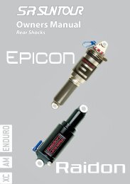
<strong>SR</strong> <strong>SUNTOUR</strong> <strong>Disc</strong> <strong>Brake</strong> Owner’s <strong>Manual</strong> <strong>DR</strong>-<strong>XCC</strong>-<strong>MC</strong><br />
<strong>DR</strong>-<strong>XCC</strong>-<strong>MC</strong> mechanical disc brake gives you the best fitted products which have been delicately<br />
designed and passed severe field and lab tests to achieve the best braking performance.<br />
Usually the disc brake you purchased has been correctly installed and properly adjusted in<br />
bikes by authorized dealers or retailers. In some cases you may buy the disc brake package<br />
independently to replace your existing direct-pulled or regular canti-brake of your bike. Although<br />
the <strong>SR</strong> <strong>SUNTOUR</strong> disc brake is designed for easy installation, it is suggested to install<br />
by trained and experienced technicians or mechanics with proper tools. If you decide to install<br />
it by yourself, please read and follow the manual’s instructions carefully before installation.<br />
This manual provides you important information about installation, operation and maintenance.<br />
If you have any problems with installation or braking performance, please stop installing or riding<br />
and contact your nearest authorized retailer for assistance.<br />
Features:<br />
1. 7/8/9 speed compatible.<br />
2. Easy installation and low maintenance.<br />
3. International standard fittings.<br />
4. <strong>Brake</strong> pads of high friction level for all weather.<br />
5. Quick and easy pad replacement.<br />
6. Compatible with regular V-type brake lever.<br />
7. <strong>Manual</strong>-adjusting turning knob for pads wearing off both sides.<br />
Components Required:<br />
1. Caliper: 1 per wheel<br />
2. Levers: “V” stroke brake levers, 1 pair.<br />
3. Rotor: 2 mm Stainless steel rotor, 1 per wheel, Front rotor = 160mm,<br />
Rear rotor = 160mm (For Manitou© 2000 fork, Front rotor : 160mm).<br />
4. Mounting Bolts: M6 x 18mm with washer, qty 4 (qty 2 for Manitou® 2000 fork)<br />
5. Rotor mounting screws: M5 x 11mm, qty 6 per rotor<br />
Tools required<br />
• Allen wrench 5mm<br />
• cable cutter<br />
• pliers<br />
<strong>Disc</strong> <strong>Brake</strong> Owner’s <strong>Manual</strong> <strong>DR</strong>-<strong>XCC</strong>-<strong>MC</strong>, page
Installation Steps:<br />
Please read these instructions thoroughly prior to attempting installation for a better understanding<br />
of this product and how it works. If you are unsure as to a component, installation<br />
procedure, or have any other relevant questions, please contact a professional bicycle dealership.<br />
step1. Mount rotor to hub by aligning bolt holes on rotor with holes on hub rotor<br />
flange, arrow side out. Using the M5 x 11mm screws, secure in a star pattern<br />
tightly. (locking torque 40-50 kg-cm) [photo 1]<br />
Caution:<br />
1. Be sure to seat the hex wrench firmly into the bolt head before tightening or<br />
loosening. Failure to do so may result in a stripped out bolt head.<br />
2. The mounting screws will need to be replaced after multiple installations and<br />
removals, as the Nylock compound wears off after 3-4 uses. Please contact<br />
a Professional Bike shop to obtain replacements.<br />
3. Turn several turns into threads with hand and then use tools when tightening<br />
mounting bolts and the cable fixing bolt to prevent stripping the threads.<br />
step2. Install wheel into fork/frame. Check wheel for proper alignment in dropouts,<br />
then tighten the wheel securely. [photo 2]<br />
step3. Remove compression module from between brake pads.<br />
step4. Mount caliper to fork or frame using the 2 M6 x 18mm Allen head bolts with<br />
washers on the side of adapter. Secure tightly. (locking torque 55-65 kg-cm)<br />
(The sticker on the back side of adapter indicates F=10.5 for front wheel and<br />
R=15.25 for rear wheel.) [photo 3]<br />
step5. Push the brake arm to lock the rotor. The caliper will move automatically and<br />
adjust into position. Securely tighten the mounting bolts (2 - M6 x 18mm) on<br />
the caliper side on the adapter. (locking torque 55-65 kg-cm) Then release the<br />
brake arm. [photo 4]<br />
step6. Turn pad adjuster B on the rear side of caliper about 1/5 turn (72deg.) counter-clockwise<br />
to make the right pad clearance. [photo 5]<br />
step7. Spin wheel in forward rotating direction. Rotor should run freely between<br />
brake pads. If not, turn back the pad adjuster B on the rear side of caliper<br />
about 1/5 turn (72deg.) clockwise and loosen the mounting bolts ( 2 - M6 x<br />
18mm) on the caliper side on the adapter and repeat step5, 6.<br />
step8. Install lever onto handlebar, Adjust angle to rider preference. Tighten clamp<br />
bolt securely. Loosen adjusting barrel and lock nut so that the grooves on<br />
the adjusting barrel, lock nut, and lever are aligned. Lightly lubricate cable<br />
with clear or white grease. Secure cable end into lever. Guide cable through<br />
grooves, tighten the lock nut against the top of the adjusting barrel and screw<br />
the adjusting barrel fully into the lever body. Slide cable through housing.<br />
[photo 6]<br />
<strong>Disc</strong> <strong>Brake</strong> Owner’s <strong>Manual</strong> <strong>DR</strong>-<strong>XCC</strong>-<strong>MC</strong>, page
step9. Guide housing through cable guides on frame (rear brake only). Guide cable<br />
through cable anchor. Cable should be between the cable lock plate and<br />
the brake arm. Snug cable fixing bolt. Zip tie cable to fork. (front brake only)<br />
Tension cable without acting brake arm. Cable should be tight with no sag.<br />
Secure cable fixing bolt tightly. (locking torque: 55-65 kg-cm) [photo 7] Cut<br />
excess cable leaving approximately 5cm length. Install cable end cap and<br />
crimp tight.<br />
Caution:<br />
The angle position of the brake arm has been specially designed. Do not change<br />
its angle position while pulling the brake cable. Otherwise, the brake performance<br />
will be affected. Besides, be sure not to adjust the adjusting barrel on the<br />
lever casually or it will also make bad influence on the brake performance.<br />
step10. Test the brake by squeezing the brake lever several times to determine if the<br />
clamping pressure is adequate. The brake pad clearance has been set at the<br />
factory. The brake actuating stroke on the lever end will be about 1-2cm. (recommended).<br />
If the clamping pressure is not good (brake actuating position not<br />
right), the possible reasons are:<br />
1. The brake cable is not tight during fixing the fixing bolt on the brake arm.<br />
Solution: Inspect the brake housing making sure the cable is secured in the lever and<br />
all ferrules are seated properly in the cable guides. Retighten the brake cable if it is not<br />
taut.<br />
Warning:<br />
Do not use the brake lever adjusting barrels to tension the cable. This will cause<br />
the brake modulation to change, resulting in decreased braking action.<br />
2. The clearance between pads is not right or the rotor contact pads.<br />
Solution: View the position of the rotor in the slot of the caliper:<br />
1) If the rotor is in the center line of the slot, adjust the pad clearance per <strong>Brake</strong><br />
Pad Adjustment instructions.<br />
2) If the rotor is not in the center line of the slot, disassemble the mounting bolts<br />
(2-M6 x 18mm) on the caliper side on the adapter and remove caliper, then adjust<br />
according to step 4, 5 of <strong>Brake</strong> Pad Replacement instructions.<br />
Notice:<br />
The braking performance may be less than 100% at first until the pads are<br />
broken-in and can achieve their normal braking performance. After the first few<br />
rides, re-tension the brake cable to take up the initial cable stretch that occurs.<br />
<strong>Disc</strong> <strong>Brake</strong> Owner’s <strong>Manual</strong> <strong>DR</strong>-<strong>XCC</strong>-<strong>MC</strong>, page
Repair and Maintenance:<br />
<strong>Brake</strong> Pad Adjustment<br />
The brake pads will be worn off during braking, which means the clearance between<br />
two pads will be bigger and the braking feeling will be worse. Therefore, it might be<br />
necessary to adjust the clearance between two pads by turning the pad adjusters so as<br />
to get the original braking performance.<br />
step1. Right turn (clockwise) pad adjuster A till A side brake pad touches rotor, check<br />
rotor not to be pushed by brake pad with eyes. [photo 8]<br />
step2. Right turn (clockwise) pad adjuster B till B side brake pad touches rotor, then<br />
there is no gap between rotor and both pads. [photo 5]<br />
step3. Left turn (counterclockwise) both pad adjusters A and B about 1/5 turn<br />
(72deg.) and get the right clearance between rotor and both pads. The brake<br />
actuating stroke on the lever end will be about 1-2cm. (recommended). Turn<br />
more will get more clearance and turn less will get less.<br />
Caution:<br />
<strong>Brake</strong> Pad Replacement<br />
Be sure not to adjust the barrel adjuster on the lever casually or it will make bad<br />
influence on the brake performance.<br />
Check the brake pads for wear. At 0.5mm or less for the thickness of brake lining, the<br />
pads are worn and must be replaced for continued safe braking.<br />
Tools required: Pliers<br />
step1. Loosen the mounting bolts (2 - M6 x 18mm) on the caliper side on the adapter<br />
and remove caliper. Left turn (counterclockwise) both pad adjusters A and B to<br />
the dead end. [photo 9]<br />
step2. Pull pad (A side) out through the slot of the caliper with pliers or with hand first<br />
and then pull pad (B side) out. [Photo 10, 11] Clean out the caliper. Dispose of<br />
the old pads properly.<br />
step3. Insert new pads according to the opposite procedure of removing pads.<br />
step4. Put caliper into rotor with the slot matching. Right turn pad adjuster B to another<br />
dead end, then right turn pad adjuster A till it clamp rotor tight. Left turn<br />
(counterclockwise) pad adjusters B about 1/5 turn (72deg.) and get the right<br />
position of pads<br />
<strong>Disc</strong> <strong>Brake</strong> Owner’s <strong>Manual</strong> <strong>DR</strong>-<strong>XCC</strong>-<strong>MC</strong>, page
LIMITED WARRANTY<br />
<strong>SR</strong> <strong>SUNTOUR</strong> warrants the disc brake to be free from defects in materials and workmanship<br />
under normal use for a period of two years from the date of purchase. In no<br />
event shall this limited warranty apply to any defect of the suspension fork caused by:<br />
improper installation, disassembly, reassembly, intentional breakage or damage, alterations<br />
or modifications to the rear shock by the user or other party or any unreasonable<br />
use or abuse of the product or any use for which this product was not intended.<br />
The obligation of this limited warranty shall be limited to repairing or replacing the<br />
disc brake or any part for which there is a defect in materials or workmanship during<br />
the two years following the date of purchase. To validate this limited warranty the purchaser<br />
must submit this warranty card to <strong>SR</strong> <strong>SUNTOUR</strong> within 30 days after purchase<br />
of the disc brake. Any alteration of, or tampering with the warranty card automatically<br />
terminates this limited warranty.<br />
<strong>SR</strong> <strong>SUNTOUR</strong> makes no express or implied warranties of fitness or merchatability of<br />
any kind, except as set forth above. <strong>SR</strong> <strong>SUNTOUR</strong>’s liability hereunder is expressly<br />
limited to repair or replacement of the product. Under no circumstances will <strong>SR</strong><br />
<strong>SUNTOUR</strong> be liable for incidental or consequential damages. Some jurisdictions do<br />
not allow the exclusion or limitation of liability of incidental or consequential damages,<br />
so the above exclusion may not apply to you. This warranty gives you specific rights<br />
and you may have other rights which vary from jurisdiction to jurisdiction. In all places,<br />
the purchaser should contact the place of purchase for information about warranty<br />
service.<br />
Contact and Service address<br />
check our web site http://www.srsuntour-cycling.com for local distrutors and<br />
service centres.<br />
<strong>SR</strong> <strong>SUNTOUR</strong> INC.<br />
No.7 Hsing Yeh Road, Fu Hsing Ind.<br />
Zone.<br />
Changhua.50606<br />
Taiwan, R.O.C.<br />
Phone: +886 (4) 7695115<br />
Fax: +886 (4) 769 4028<br />
E-mail: orders@srsuntour.com.tw<br />
<strong>SR</strong> <strong>SUNTOUR</strong> USA<br />
P.O. Box 61988<br />
Vancouver WA 98666<br />
Canada<br />
Phone: +1 (360) 737 6450<br />
Fax: 1 (360) 737 6452<br />
E-mail: service@usulcorp.com<br />
<strong>SR</strong> <strong>SUNTOUR</strong> EUROPE GMBH<br />
Am Marschallfeld 6a<br />
83626 Valley<br />
Germany<br />
Phone: +49 / (0)8024 / 3 03 81 52<br />
Fax: +49 / (0)8024 / 4 73 09 84<br />
E-mail: service@srsuntoureurope.<br />
com<br />
<strong>Disc</strong> <strong>Brake</strong> Owner’s <strong>Manual</strong> <strong>DR</strong>-<strong>XCC</strong>-<strong>MC</strong>, page